International Space Station EVA Operations -Phase 2 Hardware Lessons Learned
←
→
Page content transcription
If your browser does not render page correctly, please read the page content below
2001-01-2202

                      International Space Station EVA Operations –Phase 2
                                                Hardware Lessons Learned
                                                         David E. Anderson, Debra A. Meyer and Kashyap Shah
                                                                                         Boeing Extravehicular & Crew Systems

Copyright © 2001 Society of Automotive Engineers, Inc.

ABSTRACT

Phase 2 of International Space Station (ISS) assembly is
scheduled to be complete by mid 2001. This paper will
describe lessons learned by the hardware providers
relative to Extravehicular Activity (EVA) operation for that
hardware. With the completion of flight 7A scheduled for
June 2001, the space station will include the first set of
US solar arrays, KU band and S band antennas,
Laboratory module, Space Station Remote Manipulator
System (SSRMS), and Airlock, all EVA assembled.                   Figure 1. ISS Assembly EVA’s per year (Reference 3)
Previously launched hardware will be reconfigured by
EVA multiple times to accommodating the changing                  completed to date (see Figure 2), as seen from the
configuration of the space station to maintain operability.       Boeing Huntington Beach Engineering Mission Support
Since the use of EVA is critical to everything from               Room. This is only one piece of a larger, comprehensive
attaching whole segments to installation of external              summary of the lessons learned by NASA’s EVA team in
hardware, to reconfiguration of thermal blankets, the             total, which continues to be written. The hardware flown
EVA operability of this hardware has been an important            thus far have been designed and verified to a set of
aspect of the design. Many EVA operations, while well             general EVA requirements (see Reference 2).            In
trained for, have not been previously attempted on-orbit.         different ways, each of the ISS assembly flights has
This paper will discuss the hardware lessons learned              expanded our understanding of EVA operability beyond
from completed Phase 2 assembly flights.                          the black and white requirements ISS was designed to.

INTRODUCTION

The ISS debuted with Flight 2A in December 1998, with
two EVA’s critical to completion of its mission. Flight 2A
set the stage for ISS assembly with EVA operations
playing a critical role in assembly in stark contrast to the
assembly of the Mir space station. 9 EVA’s in 2000 tied
the shuttle record for most US EVA’s in a given year and
greatly advanced ISS to the largest and most powerful
spacecraft ever (Reference 1).            Throughout the
assembly, EVA capability both enabled mission success
and defined it. 2001. The EVA Rate doubles in 2001
and redoubles in 2002 (see Figure 1). In addition to the
obvious efficiencies required to support training and
execution of this wall of EVA, it is also critical to feed
forward lessons learned in refining EVA operable
hardware to reduce risk and cost.

This paper is intended to capture lessons learned at a            Figure 2. ISS at the completion of flight 7A.
hardware provider level for the ISS assembly flights
Table 1. Summary of EVA on STS-88 Flight 2A
EVA1 • Crew members made all umbilical
connections necessary to activate Node
1. Upon completion of the first EVA the
ground sent commands to the Node to
confirm power and activation.
EVA2 • Installation of EVA translation aids and
tools (handrails and foot restraint
sockets), installation of the early
communications (ECOMM) system
antennas, and routing of the
communications cable from the
Functional Cargo Block (FGB) to the
starboard antenna
EVA3 • To support objectives of downstream
Figure 3. ISS Configuration during Flights 2A, 2A.1 and 2A.2A assembly missions. Tasks included
installation of a large tool bag for storing
We hope to capture some of these poignant events in EVA tools outside the station and
this paper. repositioning of foot restraints.
Additionally, the two crewmembers
FLIGHT 2A NODE 1 disconnected the umbilical on PMA-2 so
that PMA-2 can be relocated in the
STS-88 lifted off on December 4, 1998 with a crew of six future. Ingress of the Node 1 and FGB to
astronauts. The mission was a total of eleven days, install ECOMM system equipment and
including 6 docked days with three EVA days. Flight 2A transfer stowage items took place
is the second of a series of flights intended to construct between the second and third EVA's, on
the Space Station over a four and a half year period. The Flight Day 8. Following the completion of
designation "A" refers to the fact that it is an American the three EVA's and Node 1 and FGB
launch. ingress activities, the orbiter undocked
from the ISS.
Flight 2A operations extend from Orbiter launch, through
mated Orbiter-Station operations, and conclude with
Stage 2 deployment. These cover payload preparation (for crew, equipment and supplies) between Node 1 and
activities, Station and Orbiter system checkout Orbiter the Functional Cargo Block (FGB). PMA-2 is located on
rendezvous and docking, Station assembly, subsystem the forward axial port end of Node 1 toward the Orbiter
activation and checkout and Orbiter departure aft payload bay. The PMAs are attached to Node 1 axial
operations. Assembly flight 2A launches the cargo ports by Common Berthing Mechanisms (CBMs). PMA-2
element, which includes Node 1 and Pressurized Mating functions as a pressurized docking interface between the
Adapters (PMA) 1 and 2. These 3 elements are pre- Orbiter and Station. The main objectives of the one
integrated on the ground. They are then launched and scheduled EVA are shown in Table 1.
attached to the Space Station as one single cargo
element (See Figure 3). The PMA2-to-Node cables lay across the Node forward
end cone after they were deployed. They had to be
Node 1 is a pressurized, environmentally controlled routed across the end cone to avoid covering the Space
element. It provides an intersection between the other Vision System (SVS) targets also on the end cone. This
pressurized elements. This intersection will be used to was worked on the ground with the EVA crew with
provide an environment for transporting people, photos taken of the area near the connectors and across
equipment and utilities for long-duration crew operations the end cone. No photos were taken of the remainder of
and activities. This node houses the supporting utility the cables back to their points of origin on the PMA. On
systems and other accommodations to facilitate such orbit, the cables did not behave the same, and were
transfers. Node 1 also contains a storage rack of pre- routed differently across the PMA prior to reaching the
positioned critical spare EVA tools. end cone. A target was partially covered and a
subsequent flight required EVA effort to clear the target.
PMA-1 is located on the rack end of Node 1 toward the Detailed photos of the entire desired configuration/EVA
forward Orbiter payload bay. The PMAs are attached to workarounds practiced on the ground would have been
Node 1 axial ports by Common Berthing Mechanisms useful if taken.
(CBMs). PMA-1 functions as a pressurized passagewayThe Node trunnion covers had late revisions made to Other tasks completed during the space walk included
them prior to launch. However, the parts were not moving foot restraints into PMA-1 and installing three
updated with the revised drawing letter. The covers were bags containing tools for use during later flights.
manifested in the mid-deck locker and were installed on
orbit. There was a right hand left hand configuration of Throughout the space walk, Jernigan and Barry were
the covers but only two were revised. However, all assisted by their crew mates as Mission Specialist Ellen
covers had the same rev letter. During the mid-deck Ochoa operated the Shuttle's robot arm to maneuver
locker bench review, the revision letters of the hardware Jernigan around Discovery's cargo bay, and Canadian
needed to be confirmed against the drawing numbers. Space Agency astronaut Julie Payette acted as
The two altered covers were supposed to go in specific "choreographer" of the space walk from Discovery's flight
locations but it was not immediately apparent which deck.
covers went in which locations. The bottom line is that
the covers were installed successfully, but not without Table 2. Summary of EVA on STS-101 Flight 2A.2A
delays and the crew just waiting while ground confirmed
which covers went in which locations. The crew had to EVA1 • Inspect & re-install OTD (Orbit
have descriptions of which cover went in each location. Replaceable Unit (ORU) Transfer
Thus, the need for confirmation of part number revision Device) to accomplish a hard dock
letters to latest revision of drawings for hardware to be configuration.
assembled/operated on orbit was needed. • Install the final parts of the STRELA
crane on the PMA1.
Also, the CETA lights that are launched on 8A but • Remove and replace port ECOMM
installed on the Node on orbit were never fit checked for system antenna due to degraded
2A because they are not launched until 8A. It was performance.
thought that 8A is so far away that attaching the CETA • Install handrails on Unity in support of
lights to the Node was not a priority task. As a result, fit future Z1 berthing flight (Flight 3A).
checks/EVA tests of were performed on the pad. That • Clear Space Vision System (SVS) target
was the first chance there was proper access to perform to support future 3A docking.
the fit checks. Some people wanted to scrub the checks • Install centerline camera cable to support
because the hardware wasn’t “2A” hardware. When the future 5A docking.
fit checks were performed, the light booms would not
seat in their receptacles on the Node due to some
mounting bolts. The heads of the bolts stuck out and Sunday's extravehicular activities culminated in the
caused interference in the soft dock position. They second longest space walk in shuttle history lasting 7
would not have mated on orbit and there was no on orbit hours, 55 minutes. The 45th space walk in space shuttle
workaround for this. When they were launched, they history and the fourth of the International Space Station
would’ve needed to be stowed or brought back home. era - began at 9:56 p.m. Central time Saturday night, and
The lesson learned here is always fit check when concluded at 5:51 a.m. Sunday morning. All of the
possible. objectives mapped out for this excursion, including a
couple of unscheduled activities were accomplished.
FLIGHT 2A.1 ISS SPACEHAB LOGISTICS
The excursion raised the total number of International
STS-96 lifted off on May 27, 1999 with a crew of seven Space Station era space walks to four, with the total time
astronauts. The mission was a total of nine days, spent on construction activities now standing at 29 hours,
including 5 docked days with two EVA days. 17 minutes. Together, STS-88 Astronauts Jerry Ross
and Jim Newman spent a total of 21 hours, 22 minutes
During Flight Day 4, STS-96 Astronauts Tammy Jernigan outside Endeavor during their three space walks.
and Dan Barry transferred and installed two cranes from
the shuttle's payload bay to locations on the outside of FLIGHT 2A.2A SPACEHAB LOGISTICS
the station. They also installed two new portable foot
restraints that will fit both American and Russian space STS-101 lifted off on May 19,2000 at with a crew of
boots, and attached three bags filled with tools and seven. The mission was a total of ten days, including 6
handrails that will be used during future assembly docked days with one EVA day. The Space Station
operations. consisted of the Russian FGB and the US Node Unity
(See Figure 3). The shuttle docked to PMA2. The main
Once those primary tasks were accomplished, Jernigan objectives of the overall flight were to perform FGB
and Barry installed an insulating cover on a trunnion pin refurbishment (install four new batteries, ten new smoke
on the Unity module, documented painted surfaces on detectors, and four new cooling fans) to extend FGB
both the Unity and Zarya modules, and inspected one of lifetime and to prepare the station for the arrival of the
two early communications system antennas on the Unity. Russian built Zvezda Service Module. The mainobjectives of the one scheduled EVA are shown in Table analysis of stowage scenarios for kinematic fit and
2. function.
During the EVA, a crewmember could not install a on FLIGHT 2A.2B SPACEHAB LOGISTICS
orbit installed handrail (OIH) in the number 8 position of
Node 1 due to lack of sufficient clearance with co-located STS-106 lifted off on September 8, 2000 with a crew of
cabling. Research on the ground showed that this seven. The mission was a total of eleven days, including
handrail did not fit in ground fit checks either, but that the seven docked days. The docked days consisted on 1
installation had been added to the EVA without properly EVA day. The Space Station consisted of the Russian
confirming the EVA checklist with the fit check data. The Progress 1 vehicle, Service Module, FGB, and the US
crew was advised to install the handrail in a position Node Unity (see Figure 4). The shuttle docked to PMA2
slightly above the planned position, which still maintained located on the US Node. The main objectives of the
the functionality. As a result of this incident, subsequent overall flight were to carry internal logistics and resupply
flights have included more comprehensive procedures to cargo for station outfitting. In addition, the crew carried
assure fit check data is confirmed before an installation out logistics transfers for arrival of the first station crew.
The main objectives of the one scheduled EVA are
shown in Table 3.
Table 3. Summary of EVA on STS-106 Flight 2A.2B
EVA 1 • Perform miscellaneous maintenance
tasks on the space station.
• Inspect Service Module “-x” docking
target.
• Connect data, communication, TV, and
power cables between FGB (Zarya) and
Service Module (Zvezda).
• Connect (1) FGB / SM Orlan
communication cable.
• Transfer and install magnetometer ferro
probe boom and foot restraint which
assists with prop usage efficiency.
• Perform checkout of Node 1 Zenith and
Nadir port CBM.
Figure 4. Configuration of ISS after flight 2A.2B
is included in an EVA.. The incident also confirms the
The EVA lasted 6 hours and 14 minutes. The only
value of reducing risk to EVA operability by conducting
anomaly noted during the EVA was that a few small
EVA fit checks and flowing the results into EVA
pieces of EVA equipment, including wire ties and a
operations.
connector cover, were suspected to have inadvertently
come free from the ISS. Lessons learned included more
The EVA community was also requested to come up with
training on object restraint, reexamining hardware to
a contingency plan for the stowage of the OTD. Photos
assure it could be confidently constrained, and
from 2A.1 showed the OTD was not fully seated into the
contingencies for loss of items.
Worksite Interface (WIF) it was mounted to. The concern
was the hardware or the WIF could be damaged.
The other difficulty the crew faced, along with the
Research showed the OTD could not be stowed
personnel on the ground, was the lack of video downlink
overnight in the Middeck or Spacehab due to weight
that made monitoring IVA ops difficult. No video was
constraints. Options for tying the OTD to Node 1 with
available during Orlan Rack Relocation. In spite this fact,
gap spanners and Equipment ties were explored in the
the crew accomplished all mission objectives
Neutral Buoyancy Lab (NBL) in Houston as the crew
successfully and touched down on September 20, 2000.
slept. The plan that was worked out was that if the OTD
could not be mounted properly to the WIF, to cut the EVA
short by 2 hours, bag the ends of the OTD, and stow it
FLIGHT 3A INTEGRATED TRUSS STRUCTURE
on Node 1 using Velcro straps. The re-installation of the Z1
OTD in the original WIF socket was successfully
completed by EVA crewmembers. Though the STS-92 lifted off on October 11, 2000 with a crew of
contingencies were not used, the integrated results of seven. The mission was a total of thirteen days. This
Shuttle, ISS design and NBL training provided a good included 4 EVA days. The Space Station consisted of
trial run in communications. Boeing designers assured the Russian Progress 1 vehicle, Service Module, FGB,
that CAD trained personnel were available to assist in and the US Node Unity, PMA 1 and 2. The mainobjective of STS-92 was to deliver Z1 and PMA 3 to the On EVA Day 1, during the setup for the Ku Boom deploy,
International Space Station. It also delivered a Ku-band the Adjustable Portable Food Restraint (APFR) would not
Communications system and Control Moment Gyros. fully engage in side-mounted WIF Z1-21. The team
began looking at alternate WIFs and APFR settings using
Support of flight 3A, as with most of the missions, started graphical analysis on CAD models of the flight hardware.
before the launch. The EVA Failure Workaround Crib It was determined that side-mounted WIFs Z1-05 and
sheet, was developed prior to flight. The crib sheet Z1-06 have a nominal overhang of 0.25” and a minimum
includes short pre-defined EVA workarounds to overhang of 0.188”, unlike Z1-01, Z1-04, Z1-21, and Z1-
supplement longer anomaly resolution plans covering 22, which are flush mounted. A thermal shield added
EVA workarounds. The crib sheet covered each EVA late to the APFR had bolts that protruded and interfered
task planned in the four EVA days on this mission. This with the installation into some WIFs. During the planning
was a major effort that should have been started a month shifts, the team received drawings of the APFR load
or two prior to the mission. The crib sheet was modified alleviator thermal shroud and fasteners. EV&CS
and updated to include all of the inputs gathered. analyzed the fit between the APFR and the side-mounted
WIF. For a flush side-mounted WIF, the thermal shroud
In the time leading up to 3A, the contractor and NASA bolts definitely interfere. All remaining 3A tasks and all
worked closely together. In a number of cases, it was planned 4A tasks were examined using side-mounted
found that changes to tool settings were needed on WIFs. They also investigated removing select fasteners
specific EVA bolts to reduce the probability of on-orbit to allow some clocking angles to be installed in flush
failure. The lesson learned was that complete data for side-mounted WIFs. Here the philosophy of EVA fit
bolt torques is needed form the hardware supplier. checks fell short since the APFR used to fit check the
WIFs before flight did not include the thermal shield. The
Table 4. Summary of EVA on STS-92 Flight 3A lesson learned both affirms the importance of doing EVA
EVA 1 • Connect Z1 Umbilicals fit checks on flight hardware and assuring those fit
• SASA Relocation checks are done with the configuration of hardware that
• Space to Ground Antenna (SGANT) will fly.
Dish Install and Boom Deploy
• Port External Tool Stowage Device
(ETSD) Install
EVA 2 • PMA 3 release from SLP
• Circuit Interrupt Device (CIDs)
Relocation
• PMA 3 Berthing
• Connect PMA 3 Umbilicals
EVA 3 • Final Z1 Umbilicals
• Stbd ETSD Install
• Final PMA 3 Umbilicals
• Z1 Keel Relocate
EVA 4 • Z1 FRGF Relocate
• Z1 Tray Deploy
• 4A APFR Relocation
Nominal torque data are used to develop EVA
procedures. The nominal, expected data also serves as Figure 5. Flight 3A umbilical connections
a diagnostic tool to recognize potential problems (e.g.
galling) as they arise. Data on torque levels where Z1 to Node 1 String 2 Umbilicals went well until the last
damage occurs was also necessary. The temptation to cable, P139 to J639, could not be reached from the
set a power tool at it’s highest setting to release a bolt SRMS by EV2. EV1 was able to free-float the
can lead to shearing off a bolt head completely if a connection, but with some difficulty. Training had not
problem occurs. With bolt damage torque levels shown that the RMS based restraint didn’t provide
understood, the tools can be set to assure no damage is access. If it had, the free-float access could have been
done. If the expected torque does not produce the trained for.
expected result, the ground and flight crew can evaluate
the situation before pushing to torques which could During the Final PMA 3 umbilical task, the P607 to J607
damage hardware. The hunger for this EVA torque data electrical connection worked properly (see Figure 5);
would increase as the assembly flights grew closer however, the connection of connector P609 to jack J609
together. failed. Due to the work on the overnight shift, everyone
knew there would be no impact if the P609 to J609 failed.The connector was left almost in soft-dock, the 609 cable second docking port for the space shuttle (see Figure 7).
was EVA wire tied to the 608 cable, and the thermal The shuttle docked to PMA2 located on the US Node.
bootie was installed to cover the connector. The main objectives of STS-97 was to build and enhance
the capabilities of the International Space Station. It
The planning shifts continued to work Flight Releasable delivered the first set of U.S. Solar Arrays and Batteries.
Grapple Fixture (FRGF) Contingencies after EVA 3. A In addition, it also delivered a set radiators to provide
number of FRGF stowage options were discussed. The cooling. The STS-97 crew conducted three space walks
FRGF release from the launch position required a higher to attach and unfurl the 73 meter (240 foot) solar arrays.
torque on at least one bolt. Then the shear pins A communications systems for voice and telemetry (S-
exhibited minor sticking, but EV4 was able to free the Band) was also installed. The main objectives of the one
FRGF with a little extra effort. The FRGF stowage went scheduled EVA are shown in Table 4.
quick and easy. A relief, based on many NBL runs
exhibiting difficulties with this interface. Here the training The STS-97 mission, with 3 EVAs, was essentially 100%
and preparation for the flight paid off in resolving this successful. During the mission, two significant ISS
problem. mission success mechanisms (Solar Array Blanket Box
(SABB) tensioning mechanism, and Beta Gimbal
Assembly 4-bar latching mechanism) had failures. But
the EVA crew was able to perform repair operations real
time and accomplished the tasks as planned.
While the crew was trying the release the Starboard BGA
launch restraints, they found the 4-bar automatic spring
deployment for latching did not occur. With manual
deployment the crew was only able to achieve 2 of 4
latching mechanisms. Planned EVA contingency
procedures to assist the 4-bar deployment with the
Payload Retention Device (PRD) was then attempted.
PRD deployment assist did achieve locking for 3 of 4
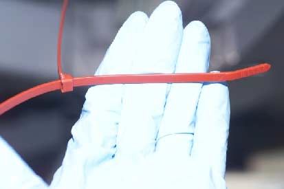
Figure 6. Wire Ties used during flight 3A
The “bow tie” (tray launch restraint) stowage presented
several difficulties. The first problem was that the bow tie
pin was difficult to install because the holes needed to be
aligned, rather than against a hard-stop. The alignment
mark was difficult to use on-orbit. The second problem
was the zip ties fell apart.(see Figure 6) The crew was
able to re-fasten three of the four zip ties and cinch them
down. They did not have a high degree of confidence
that the zip ties would hold, so they used an adjustable
equipment tether to cinch down the bow tie. The bow tie
needed to be restrained, to make the SVS targets
mounted there accurate for the P6 to Z1 mating on 4A,
and for the PMA 2 to Z1 mating on 5A.
FLIGHT 4A INTEGRATED TRUSS STRUCTURE
P6 Figure 7. ISS Configuration, flight 4A.
STS-97 lifted off on November 30, 2000 with a crew of
five. The mission was a total of eleven days, including
latching mechanisms. Having an EVA back-up to
seven docked days. ISS was staffed by its first resident
automatically deployed hardware was key to mission
crew. The docked days consisted on 3 EVA day, and 3
success in this case. The spring that should have
IVA days. The Space Station consisted of the Russian
deployed the beta gimbals did not perform as designed
Progress 1 vehicle, Service Module, FGB, the US Node
and planned EVA contingencies completed the tasks.
Unity, Z1 Truss segment, and PMA3 which provides a
This shows the value of having EVA capability – considerif this capability were available to fully open the high gain Table 6. Summary of EVA on STS-98 Flight 5A
antenna on the Galileo spacecraft. EVA1 • Secure PMA 2 to Z1 to make room for
the LAB.
Near the end of EVA 1 while the EVA Crew was into • Disconnect LTA heater umbilicals.
sortie cleanup, the Solar Array Wings (SAW) were to be • Connect Lab to Node 1 LTA heater
unlatched and deployed via IVA commanding. Starboard umbilicals.
SAW blanket box unlatching was IVA commanded and • Connect Z1 to Lab fluid QDs.
successfully completed. During starboard SAW mast EVA2 • Release PMA 2 from Z1 and relocate to
deployment, the accordion folded solar panels showed Lab.
signs of the panels sticking together. As the mast • Install PCA vent, PDGF and VSC.
deployment continued, the sticking solar panel unfolded EVA3 • Transfer spare SASA.
with a more vigorous than expected motion causing a • Connect PMA 2 to Lab umbilicals.
rippling motion/force to cascade up and down the • Incapacitated crew demonstration
partially deployed solar blanket. As the wave in the
blanket contacted the lower blanket box the SABB
tensioning cable visually appeared to be in a non- Crew for familiarization and discussion. EVA procedures
standard slack configuration. The EVA Crew was not were developed and uplinked in a flight note prior to EVA
asked to perform any other SAW contingency operations 3. SABB tension mechanism repair, consisted of re-
to assist in SAW deployment before the end of EVA 1. spooling the tensioning cables onto the tensioning reels
and was successful on the Starboard SABB. The
Table 5. Summary of EVA on STS-97 Flight 4A Starboard SAW was then latched and tensioned with the
EVA1 • Attached P6 Integrated Truss Structure Crew watching as the mechanism operated. As with the
to the Z1 Truss, which was delivered to beta gimbal deployment, EVA operability again saved the
the station on STS-92 (Flight 3A). mission. Without the EVA fix, the solar array would not
• Prepared the solar arrays and radiators have been able to sustain shuttle docking loads and
for deployment. would have had to be jettisoned.
EVA2 • Configured the space station for use of
the power from P6. Over all the STS-97 mission was a complete success.
• Positioned the S-band antenna for use by All primary and secondary mission objectives were
the space station. successfully accomplished. The P6 Photovoltaic Module
• Prepped the station for the arrival of the is performing as expected and providing the ISS with
US laboratory on Flight 5A. more than 20 Kilowatts of power. The resolution of the
EVA3 • Positioned the Floating Potential Probe SABB in-flight anomaly, was solved by NASA, Boeing,
(FPP) to measure the plasma field and support contractors working hand-in-hand to identify
surrounding the space station following repair concepts and develop EVA procedures. This
the activation of the solar. mission was dominated by the work put in by the Mission
• Arrays, and help determine the Support Teams to repair the SABB tensioning
effectiveness of the plasma contactor mechanism, however, all other mission objectives that
unit. had their own little problem and workarounds were also
• Performed repair work to increase handled in a thorough and expeditious manner.
tension in the starboard solar array
• blankets that did not stretch out FLIGHT 5A DESTINY LABORATORY MODULE
completely during deployment.
STS-98 lifted off on February 7, 2001 with a crew of five.
The mission was a total of eleven days, including seven
An anomaly resolution team was immediately formed in docked days, which was staffed by its first resident crew.
the Houston to address the SABB failure. As part of The docked days consisted of 3 EVA days, and 4 IVA
determining the problem with the SAW a Team of EVA days. The Space Station consisted of the Russian
engineers and a crew member were sent to Lockheed Progress 1 vehicle, Service Module, FGB, and the US
Martin in Sunnyvale, California, to evaluate the failure Node Unity, PMA 1, 2, and 3, and Z1. The main
modes on a future Flight SABB. The decision was made objective of STS-98 was to deliver the U.S. Laboratory
to survey the SABB problem on EVA 2 and prepare EVA Module to the International Space Station. It also
procedures to fix the problem n EVA 3. delivered a spare SASA. The STS-98 crew conducted
three space walks to complete tasks like transferring the
Between EVA 2 and EVA 3 the SABB anomaly resolution spare SASA, relocating PMA 2, and connecting PMA 2 to
team was continuing to plan the fix for the Starboard Lab umbilicals. The main objectives of the scheduled
SAW tensioning mechanisms. A video of the proposed EVAs are shown in Table 5.
re-spooling of the tensioning cable was sent up to theBefore the first EVA, EV&CS were working 2 major Leonardo. The main objectives of the one scheduled
issues: the EVA workarounds crib sheet and S-band EVA are shown in Table 6.
Antenna Subassembly (SASA) return. SASA was the
major issue. Questions of torque values and 5 or 6 Table 7. Summary of EVA on STS-102 Flight 5A.1
fasteners needed for return were raised in case the EVA1 • Relocating Pressurized Mating Adapter 3
SASA could not be released. from the Unity Node electrical cables.
The arm would follow this by moving
During EVA 1, PMA 2 was successfully relocated to Z1 PMA3 from Node 1 Nadir to Node 1 Port
and the Lab was mated and pressurized. While venting using the shuttle Remote Manipulator
M7, during the Z1 to Lab fluid quick disconnect (QD) System (RMS).
task, EV2 was sprayed with ammonia from a fluid • Remove the early communications
connector with its valve stuck partially open. There was (ECOMM) antenna.
also trouble with the caps on the male side of the QDs, • Install the Lab Cradle Assembly (LCA)
possibly because ice crystals were present. The crew rigid umbilical installation.
was told that the caps were not required, so don’t waste • Install rigid umbilicals on the US
time trying to put them back on. Laboratory.
EVA2 • Install the external stowage platform
During EVA 2, PMA 2 was mated to the Lab, but the bail (ESP).
on connector P613 was broken. This problem was • Deliver a replacement Pump Flow
worked by EV&CS planning shifts. The PCA vent task Control System (PFCS).
was skipped to complete the PDGF task. Anomaly
resolution plans written for this task did not conceive of
this particular problem. The MPLM was berthed to ISS Node 1 Nadir location
using the shuttle RMS. This berthing then followed with
During EVA 3, the 100th EVA, the spare SASA was Intra-vehicular activities (IVA) to outfit the US lab
successfully relocated, but an o-ring around connector including the following :
P4 came loose. EV&CS worked on getting the crew to • Transfer and install DDCU racks 1 & 2
bring the o-ring back for inspection rather than trash it. • Transfer and install Avionics, Mobile Servicing
EV2 also finished up the Z1 to Lab connections. He System (MSS) 1 & 2
indicated that he had better positioning this time after • Install Crew Health Care System (CheCS) racks
PMA 2 had been moved. • Transfer MPLM soft stowage items
• Transfer ISS return items in shuttle middeck
Overall, the STS-98 mission, with 3 EVAs, was The STS-102 mission, with 2 EVAs, was very successful
successful. The Space Station is now outfitted with the and all subsystems performed as expected. The EVA
U. S. Laboratory, which will be the center of all research translation paths and dedicated work sites also
on the station. performed as expected.
FLIGHT 5A.1 FIRST MULTI-PURPOSE Looking ahead to future missions, a lesson learned from
LOGISTICS MODULE (MPLM) FLIGHT this mission was to try to have more audio and video
during IVA activities. More interactive communication of
STS-102 lifted off on March 8, 2001 with a crew of ongoing IVA activities by the crew, will allow more
seven. The mission was a total of eleven days, including effective support from the ground to the crew during this
eight docked days. The docked days consisted on 2 activities. There is video transmission from stationary
EVA days, and 5 IVA days. The Space Station consisted cameras, but without a camera that sees more of what
of the Russian Progress 1 vehicle, Service Module, FGB, the crew is actually seeing makes it difficult to
the US Node Unity, Z1 Truss segment, and PMA3, P6 troubleshoot and aid the crew if an anomaly situation
truss segment, and the US Laboratory module. The were to arise.
shuttle docked to PMA2 located on the US Lab module.
FLIGHT 6A SPACE STATION REMOTE
The main objectives of STS-102 was to bring the second MANIPULATOR SYSTEM
resident crew, Expedition Two, to the station: Yury
Usachev, James Voss and Susan Helms and returns the STS-100 is scheduled to lift off on April 19, 2001, with a
first expedition crew back to Earth after four and half crew of seven. The mission will last a total of eleven
months. This flight truly lives up to the name Space days, including 2 EVA days. The main objective of STS-
Transportation System (STS). STS-102 also provided 100 will be to deliver and deploy the SSRMS or Space
logistics and resupply for the expedition crew and also Station Remote Manipulator System. It will also deliver
carried equipment to assist in outfitting of the U.S. the Rafaello Multi-Purpose Logistics Module (MPLM) for
Laboratory Module in the Italian-built MPLM named Lab outfitting and an Ultra High Frequency (UHF)
antenna.Table 8. EVA Summary for STS-100 Flight 6A Table 9 EVA Summary for STS-104 Flight 7A
EVA1 • Flight Support Equipment Grapple EVA 1 • PAD/PFR install.
Fixture (FSEGF) cable connect to • Towel Bar install.
provide and keep-alive power to SSRMS. • PCBM cover removal.
• UHF Antenna Install. • LTA jumper removal in the payload bay.
• SSRMS deployment. • Airlock to Node jumper mate.
EVA2 • J400 panel reconfiguration to remove EVA 2 • ONTO1 (O2 N2 Tank ORU) and ONTO
power from FSEGF and connect power 4 install.
to Lab power. • Airlock GF and trunnion pin cover install.
• Data Grapple Fixture (PDGF) FSEGF EVA 3 • ONTO 2 and ONTO 3 install. Orlan UHF
cable disconnect from Lab J300 panel antenna cable and Airlock handrail
LCA. install.
• Starboard ECOMM Antenna removal.
• UHF antenna connect.
• Digital Converter Signal Unit (DCSU) CONCLUSIONS
Install.
In rapid succession, flights 3A, 4A, 5A, 5a.1, have and
flights 6a and 7a will take the station from a small outpost
The Canadian-built SSRMS is needed to perform to a world class research facility, the largest and most
assembly operations on later flights. The Italian-built powerful spacecraft ever flown. EVA operations have
MPLM will carry six system racks and two storage racks been key to assembly. In executing these EVA’s, we
for the U.S. Lab. The UHF antenna will provide space- learn lessons that we must immediately apply to the wall
to-space communications capability for U.S.-based of EVA’s to come in the next 3 years. As more diverse
EVAs. The main objectives of the scheduled EVAs are teams get involved, including not only various US
shown in Table 7. contractors, but also representatives from different
countries, it becomes very helpful to have all the teams
If the DCSU install is performed on EVA 2, it will require present before, during, and after the mission. As the
the SSRMS to powerup to operational, demate SLP, and launch frequency increases, the amount of work required
maneuver away to avoid interference with SRMS in preparation for these missions will increase
translation to DCSU install position. Otherwise, it will be significantly to continually achieve mission success.
performed on the unscheduled EVA 3.
The missions thus far have shown NASA’s EVA team
In between the EVA days, there are SRMS operations and the international partners have the capability to
going on. During the MPLM Install on Node 1 nadir with accomplish nominal assembly with hard earned ease and
SRMS, there will be a clearance of less than 1 ft between meet the unexpected with teamwork and
SRMS and SSRMS. resourcefulness.
FLIGHT 7A JOINT AIRLOCK
STS-104 is scheduled to lift off on June 8, 2001. The
mission will include 3 EVA days. The main objective of
STS-104 will be to deliver the Joint Airlock to the
International Space Station. The airlock will provide
station-based EVA capability for both U.S. and Russian
spacesuits. The installation of the airlock will involve
some of the most complex assembly work of the ISS
program. The Extra vehicular activities to be performed
are shown on Table 8.
Connecting the O2/N2 umbilicals to the Airlock provides
a high pressure O2 or N2 gas supply for consumables
during Airlock and EMU servicing operations. The EVA
connection of these tanks is unprecedented. Failure to
connect these umbilicals will prevent re-supply of
consumed O2 or N2 during Airlock and EMU servicing
operations.DEFINITIONS QD Quick Disconnect
SABB Solar Array Blanket Box
APFR Adjustable Portable Foot Restraint SASA S-band Antenna Subassembly
CBM Common Berthing Mechanisms SAW Solar Array Wings
CheCS Crew Health Care System SGANT Space To Ground Antenna
CIDS Circuit Interrupt Device SSRMS Space Station Remote Manipulator System
DDCU DC-to-DC Conversion Units STS Space Transportation System
DCSU Digital Converter Signal Unit SVS Space Vision System
ECOMM Early communications UHF Ultra High Frequency
ESP External Stowage Platform WIF Worksite Interface
ETSD External Tool Storage Device
EV&CS Extravehicular & Crew Systems REFERENCES
EVA Extravehicular Activity
FRGF Flight Releasable Grapple Fixture 1. Craig Covault. 2001. “EVA Challenges Abound as
FSEGF Flight Support Equipment Grapple Fixture ISS Buildup Accelerates.” Aviation Week. March 21.
FPP Floating Potential Probe 2. David E. Anderson, “EVA Worksite Analysis – Use of
FGB Functional Cargo Block Computer Analysis for EVA Operational
ISS International Space Station Development and Execution”, MDC 98H1358, IAA-
LCA Lab Cradle Assembly 98-IAA.10.1.04, Presented at the 49th International
MBM Manual Berthing Module Astronautical Federation Congress, Melbourne,
MPLM Mini Pressurized Logistics Module Australia, 1 October 1998.
MER Mission Evaluation Room 3. Craig Covault. 2001. “Solar Array Problems Mobilize
MOD Mission Operations Directorate NASA/Contractor ISS Team.” Aviation Week.
MSS Mobile Servicing System December 11.
MBL Neutral Buoyancy Lab
OIH orbit installed handrail CONTACT
OTD Orbit Replaceable Unit Transfer Device
PRD Payload Retention Device David E. Anderson, The Boeing Company, 5301 Bolsa,
PDGF Power Data Grapple Fixture Mail Code H017-D107 Huntington Beach, CA 92647.
PMA Pressurized Mating Adapter (714) 896-3311 ext. 7-1313. E-mail:
PFCS Pump Flow Control System david.anderson@alum.mit.edu
RMS Remote Manipulator SystemYou can also read