Geometric and Radiometric Characteristics of Terrestrial Laser Scanning - A Review
←
→
Page content transcription
If your browser does not render page correctly, please read the page content below
International Journal of Pure and Applied Mathematics
Volume 118 No. 24 2018
ISSN: 1314-3395 (on-line version)
url: http://www.acadpubl.eu/hub/
Special Issue
                                                                                          http://www.acadpubl.eu/hub/

                           Geometric and Radiometric
                         Characteristics of Terrestrial Laser
                               Scanning - A Review
                                 Sajid Mahmood∗ a, Zulkepli Majidb ,
                          Khairulnizam M. Idrisc , Khairulazhar Zainuddind
                    a,b,c,d
                            Geospatial Imaging & Information Research Group,
                             Faculty of Geoinformation and Real Estate,
                                  University Technology Malaysia,
                                    Johor Bahru 81310, Malaysia
                       *Corresponding author email: msajid2@live.utm.my

                                               April 1, 2018

                                                  Abstract
                              Terrestrial laser scanning (TLS) technology have made
                         a paradigm shift in the domain of direct 3D data acquisi-
                         tion by observing thousands of points within seconds. This
                         fast 3D data acquisition capability has made TLS a leading
                         technology in a variety of applications demanding very high
                         accuracy of even millimeter level like structural deformation
                         monitoring, building information management system etc.
                         The need for highest possible accuracy necessitates that all
                         error contributing factors which may be geometric, radio-
                         metric or environmental must be thoroughly investigated.
                         This investigation will lead towards the modeling or quan-
                         tification of errors resulting from different sources and sub-
                         sequently the application of correction to the point cloud
                         for accurate results. The geometric errors resulting from
                         either instrument manufacturing mechanism or application
                         setup i.e. scanning geometry are the major error contribut-
                         ing sources followed by the radiometric characteristics of

                                                       1
International Journal of Pure and Applied Mathematics Special Issue
object and scanner. This paper discusses different geomet-
ric and radiometric characteristics of TLS by reviewing the
error modeling or quantification approaches adopted by dif-
ferent authors within last decade and half. Due to quantum
of error, the geometric properties have been evaluated more
in depth than radiometric characteristics.
Key Words:Terrestrial Laser Scanning; Geometric Char-
acteristics; Radiometric Characteristics; Point Cloud; Scan-
ning Geometry.
1 Introduction
Terrestrial laser scanners (TLS) are in operation for more than two
decades and has increasingly been used in last decade and half for
a diverse type of applications like surface reconstruction, forestry,
metrology, cultural heritage preservation, reverse engineering, mine
volume estimation, topographic mapping, architecture, urban de-
velopment, forensics, visualization and modeling artificial features
etc. This technology has made a paradigm shift in surveying from
measurement of sparsely dense individual points to fast acquisition
of accurate and highly dense 3D point cloud. Currently the TLS
systems are also equipped with external or in-built cameras to ac-
quire images of areas being scanned, thus capable of providing pho-
torealistic 3D colored point cloud (1). An overview of use of this
technology for different projects including the accuracy achieved,
efficiency and analysis can be found in (2).
Laser scanners record millions of points in very short time pro-
ducing the shapes of 3D objects in local spherical coordinate system
having origin at the center of scanner but exact shapes e.g. height,
corners etc of objects can be accurately located after going through
the process of modelling. The accuracy of 3D point cloud depends
upon the type of scanner i.e. time of flight or phase based, me-
chanical assembly precision e.g. rotation mechanism, geometrical
aspects of scanning e.g. incident angle, feature surface properties,
environmental impacts, mixed pixel phenomenon, thermal expan-
sion, instrument vibration and errors in post processing of point
cloud due to registration and filtering (3) and (4).
The technical specifications including different accuracies of laser
scanners provided by the manufacturers are usually observed under
2International Journal of Pure and Applied Mathematics Special Issue
laboratory conditions using specific surfaces. In actual, the natu-
ral scenery presents a large variety of surfaces to be scanned, the
scanning geometry is different along with presence of different envi-
ronmental and atmospheric conditions. This necessitates the iden-
tification of errors resulting from different sources, their modeling
or quantification for adjustment in final product. This paper sum-
marizes the work done on modelling or quantification of geometric
and radiometric characteristics of different error contributing fac-
tors. Major focus is on the geometric properties as compared to
radiometric.
2 Terrestrial Laser Scanning Technol-
ogy
A rotating polygonal or monogon mirror or prism or head mech-
anisms, nodding mirrors or a mishmash of these deflect the laser
pulse towards the target at known horizontal and vertical angles
(, ) which are then used in conjunction with the range to com-
pute the position of the target in 3D Cartesian Coordinates with
respect to scanners coordinate system. Usually the wavelength of
laser ranges from 0.5 m to 1.5 m and scan rates are as high as 1 mil-
lion points/sec and accuracy can be achieved in millimeters. Many
systems are now capable of measuring multiple returns of a single
pulse, generally four, and some measures full waveform of return-
ing pulse. They are classified based on the scanning area coverage
(Figure 1) and measurement technology.
2.1 Classification Based on Area Coverage
2.1.1 Panoramic Scanners
These scanners can measure the distance and angles to points in
360 horizontal and ¿300o in vertical planes.
2.1.2 Hybrid Scanners
They can capture the data 360o in horizontal plane but in vertical
data capture capability is usually restricted to 50o 60o.
3International Journal of Pure and Applied Mathematics Special Issue
2.1.3 Camera-type Scanners
These scanners are designed to collect data in a specific field of view
(FOV) like photogrammetric cameras e.g. 40o x 40o FOV.
Figure 1. Terrestrial Laser Scanner Classification Based on Area
Coverage (5)
2.2 Classification Based on Measurement Tech-
nology
2.2.1 Triangular Laser Scanners
In these types of scanners, the range is determined by the principle
of triangulation. The triangle is formed by a point in instrument
from where the laser is projected, the target point and where pulse
is received at the projection center of a camera (Figure 2). The
angle of optical axis of camera and of laser profile plane is known
through calibration along with the distance between camera pro-
jection center and laser projector. Finally the position of each laser
spot is computed using the relative distance between laser projector
and camera, known angles and the photography scale (6).
Figure 2. Triangular Laser Scanner Principle (6)
4International Journal of Pure and Applied Mathematics Special Issue
2.2.2 Time of Flight (TOF - Pulse Based) Laser Scanners
It works on the principle of measuring the time delay between the
transmitted and the back scattered pulse from a surface (Figure 3)
using the formula:
D= (c*t)/2
Where c is speed of light. These scanners use laser pulses instead
of continuous waves and scan the area point by point. In these
scanners, the transmitted laser power is highly concentrated leading
to good signal to noise ratio (SNR) which results in high accuracy
at long ranges (7).
Figure 3. TOF Laser Scanner Principle (7)
2.2.3 Phase Difference Laser Scanners
These scanners use the difference in phase of the emitted and re-
flected pulse of an Amplitude Modulated Continuous Wave to get
the range (Figure 4). The range to the target can be found using
the formula:
D= c/4π∗(∆φ)/fm od Where is the phase difference and fm od is
the modulation frequency. The range of these scanners is generally
less than 100 m and due to this reason, they are mostly used for
indoor applications.
Figure 4. Phase Difference Laser Scanner Principle (8)
5International Journal of Pure and Applied Mathematics Special Issue
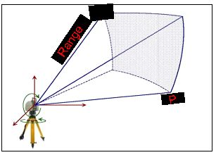
3 Geometrical Aspects
3.1 Range
It is defined as the distance between the laser deflection points in-
side scanner head to the reflection points Pi on the target (Figure
5). It depends on pulse repetition rate (PRR) of the scanner be-
cause as the PRR increases, the emitted energy of pulse decreases
and so there may not be enough reflection which is required for de-
tection (9). Range errors can be computed by measuring the known
distance to the object if the scanner is equipped with known ref-
erence point otherwise it can be ascertained using known distances
among natural or artificial objects within scanning area. The range
noise deviation can also be obtained by scanning and modelling a
planner object and noting the single point deviations.
Figure 5. Range of TLS from Points P1 and P2 (10)
(11) used spheres of known dimensions placed at known dis-
tances and quantified range errors for different scanners. They ob-
served that range error is directly proportional to distance between
target surface and scanner and noted a variation in standard devia-
tion of 1 to 5 mm for 50 m distance. (12) used three different types
of targets and found that the error in range measurement increases
with increase in measuring distance. (13) observed the dependence
of range accuracy on distance and quantified a range correction of
about 2 mm between measuring distances of 5 m to 25 m. (14)
tested Leica ScanStation 2 scanner for range differences using three
different types of targets and confirmed their previous investigation
of increase in range error for longer distances. They didnt develop
any model but produced graphical representation of error over dif-
ferent ranges. Maximum error reported is about 18 mm for a range
6International Journal of Pure and Applied Mathematics Special Issue
of 287 m. (15) developed a standard artifact consisting of spheres
(100 mm diameter) and cubes of different sizes mounted on a frame
for investigations on geometric properties of TLS LMS-Z390i. They
measured the distances between sphere centers from three ranges
of 10, 30 and 50 m for four different step widths and observed that
accuracy is dependent on range and was below 8 mm. (16) ana-
lyzed the accuracy of range by scanning different geometric shaped
objects from different distances having different resolution. They
used Z+F IMAGER 5006i, a phase difference scanner and com-
pared the object lengths obtained from scanning (maximum scan-
ning distance 10 m) and measurement by caliper and reported that
measurement differences were directly dependent on range. (17)
used black and white circular targets placed on eight pillars having
different distances among them and measured distances using Leica
ScanStation C10. They observed a standard deviation of 1.4 mm
in distance measurement observations.
Range error modelling has been carried out by many authors for
different terrestrial laser scanners. (18) proposed range error model
with eight additional physical and empirical parameters addressing
the systematic errors inferred from residual trends and achieved
an overall improvement of 48% in RMSE. (19) modified the radar
range equation which designates the received energy as compared
to emitted energy for laser beam by assuming the reflectivity from
Lambertian surface. The model shows that the received energy is
inversely proportional to the square of range and so the effect of
range in total error budget is directly proportional to range square.
This led them to modelling a coefficient depicting measurement
deterioration for different range measurements. They tested the
developed model for planner surface under laboratory conditions.
(20) used the range error model proposed by (18) to find out the
range error in Faro Photon 120 scanner and found an improvement
of 27% in RMSE.
3.2 Incident Angle
It is defined as the angle between normal to the surface N and the
incident laser beam P (Figure 6) and depends upon the orienta-
tion of the target surface with respect to laser beam. The laser
beam shape, spot size and reflectivity of the target are dependent
7International Journal of Pure and Applied Mathematics Special Issue
on incident angle because laser spot deformed to an elliptical shape
compared to orthogonal alignment of beam resulting into less re-
flectivity which affects the scanned distance and hence 3D accuracy.
It can be explained in two ways, firstly, the ellipse center deviates
from point to which the distance is being measured thus elongat-
ing the distance or secondly, more signal strength is reflected from
closer part of elliptical spot leading to shortening of distance.
Figure 6. Incident Angle Schematic Representation (21)
(12) tested five different scanners for investigation of effects of
incident angle and found that increase in angle, results in decrease
in point cloud accuracy and also time of flight scanners are influ-
enced less than the phase difference scanners. They have not mod-
eled the effect but just measured the effect of incident angle for
different scanners. (3) observed that density, intensity and accu-
racy of point cloud decreases with increase in incident angle. They
used phased based scanner and measurements were made from a
distance of 10 m only. (14) stated that accuracy of any laser scan-
ner is adversely influenced by incident angles of more than 45o
and also reported that time of flight scanners are less affected as
compared to phase difference scanners. (21) and (19) developed
a mathematical model of the influence of incident angle on range.
Their model depends on the angular information of every scan point
in point cloud as well as the normal vector of surface at every scan
point. The test of model revealed that incident angle contribute
approximately 20% to the total error budget of a particular scan
point.
(13) observed a decrease of about 0.4 mm in standard devia-
tion of range measurement with increase in incident angle. They
attributed this phenomenon towards that particular laser scanner
(HDS 6000, Leica) used for the scanning by saying that it might be
due to its characteristics of higher accuracy for angle as compared
8International Journal of Pure and Applied Mathematics Special Issue
to range. (22) investigated and quantified the effect of incident an-
gle using a TOF scanner and total station on reflectorless distance
measurement from different distances ranging from 3.5m to 30m.
They observed that effect of incident angle is not as prominent as
of other factors at close ranges of 3.5 and 5.2 m but detected a sys-
tematic effect of 1.7 mm and 2.0 mm for rough and smooth surface
respectively at 30 m range.
3.3 Scanners Angular Error
It refers to the angular error between any two adjacent vertical
or horizontal laser rays and contributes towards the range and in-
cident angle. The error resulting from the angle reading device
or caused by non-alignment of axes (Figure 7) propagate in a di-
rection perpendicular to the laser path. (18) proposed the error
models for both horizontal and vertical angles by adding 7 and 4
additional parameters respectively for both. It not only linearized
the model but also eliminated the initial approximate values and
obtained improvements of 80% and 74% in RMSE for horizontal
and vertical angle errors respectively. (23) improved the systematic
error model of collimation axis by trying to reduce the correlation
between scanner orientation angles and collimation axis error and
demonstrated an improvement in systematic error coefficients of an-
gles and hence improved precision of angular additional parameters.
For panoramic scanners, it was possible to reliably estimate the er-
ror of collimation axis but was not possible for hybrid scanners due
to their strong correlation with rotation angle about vertical axis.
(17) observed the accuracy of horizontal and vertical angles of
Leica ScanStation C10 scanner as 0.012o and 0.008o respectively.
They used eight black and white targets distributed on four walls
of a room (3.5 to 5.5 m range) and measured the angles amongst
them and used angles measured by Leica TM5100A theodolite hav-
ing an accuracy of 0.00014o for both angles as reference. (20) used
horizontal and vertical angle error models proposed by (18) and
modified these for Faro Photon 120 scanner and observed an im-
provement of 27% in RMSE of both angles after applying the error
correction. They scanned 138 black and white targets from seven
different locations in a room of dimension 15.5m x 9m x 3m. (24)
used ray-tracing method and proposed a systematic error model for
9International Journal of Pure and Applied Mathematics Special Issue
horizontal direction observations as a function of elevation angle.
He conducted ray-tracing simulation for a panoramic scanner over
full vertical angular range and confirmed that two mirror inclination
errors affect the observations in horizontal direction in same way as
the non-orthogonality of trunnion and collimation axes errors.
Figure 7. Angular Error Due to Mechanical Axes Error (25)
3.4 Resolution
It is defined as the ability of the scanner to discriminate small ob-
jects in a point cloud. It is also interchangeably known as spatial
resolution or point density. It depends on the angular increment
capability of scanner, the laser beam width which affects size of
the laser footprint (affects spot spacing or sampling step) on the
object and is a function of range and PRR of the scanner. (11) are
among the first who tested the resolution of different scanners by
scanning a star shaped object from two different distances (6 m and
22 m) and produced the results for visual observation for various
scanners. As the resolution is dependent on the sampling interval
and the laser beam width so defining the resolution based on only
one factor will lead to misunderstanding e.g. in a fine sampling
interval, fine details may be blurred if the beam width is large as
compared to the sampling interval. (26) proposed and modelled
a new term for laser angular resolution as Effective Instantaneous
Field of View (EIFOV) using Average Modulation Transfer Func-
10International Journal of Pure and Applied Mathematics Special Issue
tion (AMTF) which is used for modelling of positional uncertainty
due to sampling interval and laser beam width. (27) further eval-
uated EIFOV for few instruments assuming that angular position
has uniform effect over laser foot print and found that beam width
has the maximum restraint on EIFOV. (15) observed through an
experiment that resolution should not be defined only on scanner
step width and range but beam divergence should also be consid-
ered which conforms the observation of (26). (28) observed that
resolution estimate i.e. EIFOV is somehow pessimistic and pro-
posed a model for ratio of sampling step and target separation as
a function of range for ILRIS-3D laser scanner for maximum range
of 100 m. They proposed that optimal spot spacing should be ob-
tained using their model for a specific target spacing identification
i.e. the spatial resolution.
Since different projects require different scanning resolutions so
while deciding about the scan resolution, one should bear in mind
that higher resolution will require more points to be scanned, thus
more time, storage capacity, processing time and high specs hard-
ware. Historic England ( Former English Heritage) has developed
some guide lines for deciding about the scan resolution and has
produced a table (Table-1) for various sizes of objects (29).
Table 1: Object Size vs Scan Resolution (29)
3.5 Beam Width
It is defined as the width of laser beam relative to range along a di-
rection perpendicular to the beam axis (Figure 8) and also depends
on the beam divergence. This will result into a certain size of the
laser footprint and when it hits some edge, a part will be reflected
back from the object, a part from adjacent object or any other
object immediately behind the target or will not reach back due
to non-availability of any object. It can be expressed by following
equation (30);
11International Journal of Pure and Applied Mathematics Special Issue
p
w(ρw ) = wo (1 + ((λρw )/(πwo2 ))2 )
Where λ is wavelength, w is beam waist at distance ρ and wo
is minimum beam waist. It will affect the targets angular location
which will further add to the targets position uncertainty. (30)
modeled the effect of laser beam width as an uncertainty in the
horizontal and vertical angles which affects the range and quantifies
an approximate range error of 0.15 m for a 3-mrad beam divergence
and 450 incident angle at 100 m range for a specific laser scanner.
Figure 8. Beam Waist, Width and Angular Divergence (25)
3.6 Georeferencing
Interpretation of any geospatial data requires that it should be re-
ferred to its correct geographical location. Transformation of a
point cloud to a superior coordinate system (Figure 9) require ei-
ther the ground control points (GCPs) and/or spots or locating the
exact position of scanner by mounting a GNSS system over its top
(31). Based on these requirements, mainly there are two methods of
georeferencing, direct and indirect methods. The geometrical and
error models and related uncertainties for direct georeferencing has
been discussed by (32) and a detailed review for both methods can
be found in (33). For indirect georeferencing, first the orientation
parameters of point clouds are computed by 3D transformations
using well distributed GCPs across the entire area which increases
time and cost of the scan. Many algorithms have been developed for
finding out the orientation parameters automatically. (34) summa-
rized the related work and presented an analysis of such algorithms
and also proposed a computer vision (CV) method for extraction
of tie points to be used for orientation. His proposed method con-
sists of processing the data into raster form and then search for tie
points for orientation.
12International Journal of Pure and Applied Mathematics Special Issue
Figure 9. Geographic and Internal Reference Systems (32)
3.7 Scanners Location / Scanning Stations
The location of the scanner for survey of certain object/feature/area
should be chosen in such a way that it should ensure maximum cov-
erage using minimum number of setups and required accuracy. The
location should produce least shadows, fulfil the maximum/minimum
range limits, avoids large incident angles and minimize the number
of scan positions. Not as much of work has been conducted for
finding optimal placement of scanner and mostly solutions to this
problem are proposed based on experiences and personal intuition.
(3) and (19) quantified the effect of location of scanner on the
quality of point cloud and obtained an improvement of 25% by
changing the location of scanner. The position of scanner was cho-
sen in such a way so as to reduce the error contribution due to range
and incident angle. (35) tried to exploit the constraints of scanning
geometry (range and incident angle) to model the optimum interior
measurement locations for scanner. They made the assumptions
that a 2D map of the building is available and the registration of
scans is carried out using correspondent surface adjustment and
used the greedy approach for development of TLS placement algo-
rithm. (36) used genetic algorithm for finding optimum locations
of scanner for indoor mapping with the same assumption of avail-
ability of 2D drawings.
(37) proposed a method to find the next best scanning position
using computer for modelling of as built complex piping system.
Their approach used the assumption that size of the piping system
is approximately known and proposed to find the next best position
using voxel space based method. (38) tried to discuss thoroughly
13International Journal of Pure and Applied Mathematics Special Issue
the impacts of scanners location on identification of optimum view-
points and accuracy. They proposed a method of finding minimum
locations by simulation of laser point cloud and then applying the
other filters like range, required resolution etc. They presented the
simulation example of a statue which may not be applicable in ac-
tual terrain survey consisting of multi-shaped and multi-dimension
features. (39) proposed a stochastic model for view point planning
for reflectorless measurements utilizing reflected energy as input.
Their model is based on the argument that distance measurement
noise depends on strength of received signal. They conducted scan-
ning from different distances (5 to 55 m with 5 m increment) using
eight different radiometric samples and plotted the results as inten-
sity vs distance measurement precision and subsequently proposed
the model. The applicability of model yet needs to be verified for
natural features having different intensities even from one distance
due to multicolor composition.
4 Radiometric Aspects
All scanners record the reflected energy from the surface which
depends upon the optical and physical properties of the materials.
Different materials behave differently to the incident energy which
will affect the final output so it seems necessary to discuss the effects
of object properties on laser output.
4.1 Color
The color of any object will affect the reflected intensity values
which is used for range measurement therefore spectral character-
istics of emitted laser beam (wavelength corresponding to green or
red or near infrared etc.) will have influence on detection of col-
ored objects . (40) used CYRAX 2500 laser scanner and examined
the quality of measurement for different surfaces using different
building materials and a standardized color patches. They scanned
from varying angles and ranges and observed a significant change in
measurement quality for materials having different color and tex-
ture. (13) used different color targets and found that light color
targets reflected more than dark color targets and intensity value
decreases with increase of distance and incident angle. However
14International Journal of Pure and Applied Mathematics Special Issue
they reported a phenomenon of more value of standard deviation
for bright color targets as compared to dark color targets which is
conflicting towards range accuracy.
(41) carried out scanning of different colored objects with multi-
ple textures from different ranges and incident angles and reported
that a correlation exists between spectral characteristics of emitted
laser beam, object color and texture and the range and incident
angle. (22) reported a distance dependent systematic cyclic effect
of up to 4.4 mm for a dark green color material. (42) studied the
effect of color on laser distance measurement using total station
and concluded that color not only affect the precision of distance
measurement but also on time because dark objects reflect less as
compare to light objects.
4.2 Reflectivity and Texture
The object reflectivity influences the measurements made by laser
scanning because the laser scanner rely on the reflected signal. Too
much reflected intensity and very low values can cause ambiguities.
For a Lambertian surface, the reflected energy can be expressed by
Lamberts cosine law:
IR (λ) = Ii (λ) ∗ kd (λ) ∗ cosφ
Where IR (λ) and Ii (λ) are the reflected and incident energies
respectively which are function of wavelength, kd (λ) is isotropic re-
flection coefficient and φ is the incident angle. It can be inferred
that accuracy of point will be corrupted with noise for surfaces
with less reflectivity and there may be no reflected energy for sur-
faces having high reflectivity if the angle of incident is high (7).
(9) reported a graph showing dependency of range on pulse energy
and target reflectivity for Riegl VZ-400 scanner. Target bright-
ness also contribute towards change in reflectivity thus leading to
noise. This is significant at large incident angles usually 70o and
has little or no effect at angles ≤30o (43). Roughness of the sur-
face is generally characterized by texture also affect the reflectance
of incident energy. (11) observed systematic errors resulting from
scanning of different surfaces having different reflectivity character-
istics and concluded that this characteristics of objects will be more
pronounced in objects made of different materials. (13) tested dif-
ferent building materials having different texture and observed and
15International Journal of Pure and Applied Mathematics Special Issue
quantified the corrections for different ranges and incident angles.
(44) investigated the effect of grain size on behavior of incident an-
gle by scanning five classes of sand with grain sizes ranging from
smaller than 125 µm to more than 500 m and four classes of sugar
with grain sizes ranging from smaller than 50 µm to larger than
3400 m using Leica HDS6100 scanner from a distance of 1.65 m.
They observed no significant dependency of incident angle on grain
size for sizes smaller than the laser spot. (13) carried out an experi-
ment to find the effect of surface reflectivity on range measurement
using surfaces having different reflectivity (5%, 20%, 50%, 90% and
98%). They found standard deviation of range measurement from
25m to be 5.3 mm for surface having 5% reflectivity and ±1.0 mm
for surface with 98% reflectivity. (42) studied the effect of incident
angle on different texture surfaces using total station and observed
that as the roughness increases, apparent distance also increases.
5 Findings
The geometrical characteristics of TLS have been studied and eval-
uated by many authors for different scanners and either the errors
are quantified or modeled but mostly for specific situations or spe-
cific scanners. Although some errors like those related to range
can be applied to different scanners but most errors are specific to
particular scanners and we can say that a global error model or
quantification is still absent. The reason for this may be the differ-
ent scanning mechanisms developed by different manufacturers, but
for a particular scanner, a comprehensive error model or quantifica-
tion could have been proposed instead of modeling or quantifying
individual error sources. This will be easily understood and subse-
quently used by mediocre surveyors involved in general topographic
surveying. The developed models are mostly used for very high pre-
cision surveys of small areas or features requiring millimeter level
accuracy and may not be that significant for large area topographic
surveys. The optimum cloud topographic model for generation of
digital terrain models (DTM) at national level needs to be studied
for development of high quality DTM to be used for a variety of
applications.
The study of radiometric characteristics also reveals error mod-
16International Journal of Pure and Applied Mathematics Special Issue
eling or quantification for different colors or textures or surfaces and
for specific scanners and so lacks the global applicability of correc-
tions for different error contributing factors due to presence of di-
verse nature of features in natural landscape. One scan by scanner
will detect a variety of colors and textures present in nature so ap-
plying error models for specific color, texture or surface will not be
possible. This necessitates development of models which are nearly
global in nature and are acceptable for most types of scanners and
applications.
6 Conclusion
Every surveying application require a specific standard of accuracy
to be met and this can only be ensured by having a thorough knowl-
edge of all the factors contributing towards the error budget. This
will not only ensure that the requisite accuracy has been achieved
but will also help in minimizing the final incurred cost on surveying.
There are many sources of errors which may be significant for some
applications and may not be for others. Geometric and radiomet-
ric characteristics plays an important role in the accuracy of point
cloud leading to final 3D accuracy of the 3D model. Different ap-
plications require different accuracy standards and highest possible
accuracy cannot be achieved without the knowledge of most impor-
tant error contributing factors. Systematic and random errors re-
sulting from different instrument components, scanning geometry,
scanning environment, atmospheric conditions, object properties
and post processing procedures have been studied in much detail
and further improvements are still ongoing. Many errors have been
either modeled or quantified for different scanners and can be ap-
plied to the final product.
References
[1] Luh LC, Setan H, Majid Z, Chong AK, Tan Z, editors. High
resolution survey for topographic surveying. IOP Conference
Series: Earth and Environmental Science; 2014: IOP Publish-
ing.
17International Journal of Pure and Applied Mathematics Special Issue
[2] Pinkerton M. Terrestrial laser scanning for mainstream land
surveying. Survey Quarterly. 2011;300(65):7.
[3] Soudarissanane S, Lindenbergh R, Gorte B, editors. Reducing
the error in terrestrial laser scanning by optimizing the mea-
surement set-up2008: International Society for Photogramme-
try and Remote Sensing.
[4] Lichti DD. A review of geometric models and self-calibration
methods for terrestrial laser scanners. Boletim de Cincias
Geodsicas. 2010a;16(1).
[5] Petrie G, Toth CK. Terrestrial laser scanners. Topographic
Laser Ranging and Scanning Principles and Processing.
2009:87-128.
[6] Majid Z, Chong AK, Setan H. Important considerations for
craniofacial mapping using laser scanners. The Photogrammet-
ric Record. 2007;22(120):290-308.
[7] Genechten BV, Caner H, Heine E, Garca JLL, Poelman R,
Santana M. Theory and practice on Terrestrial Laser Scanning:
Training material based on practical applications. 2008.
[8] Soudarissanane S. The geometry of terrestrial laser scanning;
identification of errors, modeling and mitigation of scanning
geometry: TU Delft, Delft University of Technology; 2016.
[9] Pirotti F, Guarnieri A, Vettore A. State of the art of ground
and aerial laser scanning technologies for high-resolution to-
pography of the earth surface. European Journal of Remote
Sensing. 2013;46(1):66-78.
[10] Gikas V. Three-dimensional laser scanning for geometry doc-
umentation and construction management of highway tunnels
during excavation. Sensors. 2012;12(8):11249-70.
[11] Boehler W, Vicent MB, Marbs A. Investigating laser scanner
accuracy. The International Archives of Photogrammetry, Re-
mote Sensing and Spatial Information Sciences. 2003;34(Part
5):696-701.
18International Journal of Pure and Applied Mathematics Special Issue
[12] Kersten TP, Mechelke K, Lindstaedt M, Sternberg H. Geo-
metric Accuracy Investigations of the Latest Terrestrial Laser
Scanning Systems Integrating Generations FIG Working Week
2008 14-19 June 2008 Stockholm, Sweden 2008.
[13] Voegtle T, Wakaluk S. Effects on the measurements of the
terrestrial laser scanner HDS 6000 (Leica) caused by different
object materials. Proceedings of ISPRS Work. 2009;38:68-74.
[14] Kersten TP, Mechelke K, Lindstaedt M, Sternberg H.
Methods for geometric accuracy investigations of terrestrial
laser scanning systems. Photogrammetrie-Fernerkundung-
Geoinformation. 2009;2009(4):301-15.
[15] Gonzlez-Jorge H, Riveiro B, Armesto J, Arias P. Standard ar-
tifact for the geometric verification of terrestrial laser scanning
systems. Optics & Laser Technology. 2011;43(7):1249-56.
[16] Alkan RM, Karsidag G, editors. Analysis of the accuracy of
terrestrial laser scanning measurements. FIG Working Week;
2012.
[17] Abbas M, Setan H, Majid Z, Chong AK, Idris KM, Aspuri A.
Calibration and accuracy assessment of leica scanstation c10
terrestrial laser scanner. Developments in Multidimensional
Spatial Data Models: Springer; 2013a. p. 33-47.
[18] Lichti DD, Licht MG. Experiences with terrestrial laser scan-
ner modelling and accuracy assessment. Int Arch Photogramm
Remote Sens Spat Inf Sci. 2006b;36(5):155-60.
[19] Soudarissanane S, Lindenbergh R, Menenti M, Teunissen P.
Scanning geometry: Influencing factor on the quality of terres-
trial laser scanning points. ISPRS Journal of Photogrammetry
and Remote Sensing. 2011b;66(4):389-99.
[20] Abbas M, Setan H, Majid Z, Chong AK, Luh LC, Farid M,
et al. Improvement in accuracy for three-dimensional sensor
(Faro Photon 120 scanner). 2013b.
[21] Soudarissanane S, Lindenbergh R, Menenti M, Teunissen P,
editors. Incidence angle influence on the quality of terrestrial
laser scanning points2009: ISPRS.
19International Journal of Pure and Applied Mathematics Special Issue
[22] Zmenkov M, Neuner H, Pegritz S, Sonnleitner R. Investigation
on the influence of the incidence angle on the reflectorless dis-
tance measurement of a terrestrial laser scanner. Vermessung
& Geoinformation. 2015;2(3):2015.
[23] Lichti D. The impact of angle parameterisation on terrestrial
laser scanner self-calibration. Int Arch Photogramm Remote
Sens Spat Inf Sci. 2009;38(3/W8):171-6.
[24] Lichti DD. Ray-Tracing Method for Deriving Terrestrial Laser
Scanner Systematic Errors. Journal of Surveying Engineering.
2016:06016005.
[25] Reshetyuk Y. Self-calibration and direct georeferencing in ter-
restrial laser scanning: KTH; 2009.
[26] Lichti DD. A resolution measure for terrestrial laser scan-
ners. The International Archives of the Photogrammetry, Re-
mote Sensing and Spatial Information Sciences. 2004;34(Part
XXX):6.
[27] Lichti DD, Jamtsho S. Angular resolution of terrestrial laser
scanners. The Photogrammetric Record. 2006a;21(114):141-60.
[28] Pesci A, Teza G, Bonali E. Terrestrial laser scanner resolution:
Numerical simulations and experiments on spatial sampling
optimization. Remote Sensing. 2011;3(1):167-84.
[29] Barber D. 3D Laser Scanning for Heritage (second edition)
Advice and guidance to users on laser scanning in archaeology
and architecture In: Heritage E, editor. 2011.
[30] Lichti DD, Gordon SJ, Tipdecho T. Error models and propaga-
tion in directly georeferenced terrestrial laser scanner networks.
Journal of surveying engineering. 2005a;131(4):135-42.
[31] Pfeifer N, Briese C. Geometrical aspects of airborne laser scan-
ning and terrestrial laser scanning. International Archives of
Photogrammetry, Remote Sensing and Spatial Information
Sciences. 2007a;36(3/W52):311-9.
20International Journal of Pure and Applied Mathematics Special Issue
[32] Scaioni M. Direct georeferencing of TLS in surveying of
complex sites. Proceedings of the ISPRS Working Group.
2005;4:22-4.
[33] Akmalia R, Setan H, Majid Z, Suwardhi D. Methods for Geo-
referencing Point Cloud of Building From Static TLS: A Re-
view. Developments in Multidimensional Spatial Data Models:
Springer; 2013. p. 207-18.
[34] Markiewicz JS. The use of computer vision algorithms for au-
tomatic orientation of terrestrial laser scanning data. ISPRS-
International Archives of the Photogrammetry, Remote Sens-
ing and Spatial Information Sciences. 2016:315-22.
[35] Soudarissanane S, Lindenbergh R. Optimizing terrestrial laser
scanning measurement set-up: International Society for Pho-
togrammetry and Remote Sensing (ISPRS); 2011a.
[36] Kim M-K, Li B, Park J-S, Lee S-J, Sohn H-G, editors. Op-
timal locations of terrestrial laser scanner for indoor mapping
using genetic algorithm. Control, Automation and Information
Sciences (ICCAIS), 2014 International Conference on; 2014:
IEEE.
[37] Kawashima K, Yamanishi S, Kanai S, Date H. Finding the
next-best scanner position for as-built modeling of piping sys-
tems. The International Archives of Photogrammetry, Remote
Sensing and Spatial Information Sciences. 2014;40(5):313.
[38] Wujanz D, Holst C, Neitzel F, Kuhlmann H, NIEMEIER
W, SCHWIEGER V. Survey configuration for terrestrial
laser scanning. Allgemeine Vermessungsnachrichten (AVN).
2016a;6(2016):158-69.
[39] Wujanz D, Mettenleiter M, Burger M, Neitzel F. Viewpoint
planning for terrestrial laser scanning utilising an intensity
based stochastic model. 2016b.
[40] Clark J, Robson S. Accuracy of measurements made with a
Cyrax 2500 laser scanner against surfaces of known colour.
Survey Review. 2004;37(294):626-38.
21International Journal of Pure and Applied Mathematics Special Issue
[41] Kavulya G, Jazizadeh F, Becerik-Gerber B. Effects of color,
distance, and incident angle on quality of 3D point clouds.
Computing in Civil Engineering (2011)2011. p. 169-77.
[42] Daliga K, Kuraowicz Z. Examination method of the effect of
the incidence angle of laser beam on distance measurement ac-
curacy to surfaces with different colour and roughness. Boletim
de Cincias Geodsicas. 2016;22(3):420-36.
[43] Kukko A, Kaasalainen S, Litkey P. Effect of incidence angle
on laser scanner intensity and surface data. Applied Optics.
2008;47(7):986-92.
[44] Krooks A, Kaasalainen S, Hakala T, Nevalainen O. Correc-
tion of intensity incidence angle effect in terrestrial laser scan-
ning. ISPRS Ann Photogramm Remote Sens Spat Inf Sci.
2013;2:145-50.
22You can also read