RESECTION AND MONTE CARLO COVARIANCE FROM VANISHING POINTS FOR IMAGES OF UNKNOWN ORIGIN
←
→
Page content transcription
If your browser does not render page correctly, please read the page content below
The International Archives of the Photogrammetry, Remote Sensing and Spatial Information Sciences, Volume XLIII-B2-2020, 2020
                                               XXIV ISPRS Congress (2020 edition)

  RESECTION AND MONTE CARLO COVARIANCE FROM VANISHING POINTS FOR
                    IMAGES OF UNKNOWN ORIGIN

                                                         Reuben Settergren

                                   BAE Systems, Geospatial eXploitation Products™ (GXP® )
                        10920 Technology Drive, San Diego CA – reuben.settergren@baesystems.com

KEY WORDS: Photogrammetry, vanishing points, parallel lines, resection, 3D scene reconstruction

ABSTRACT:

Photogrammetric analysis requires camera metadata (position, attitude, interior orientation, etc.), which is not available for all im-
ages. Modern commercial solutions for 3D reconstruction from images typically assume large amounts of purposefully-collected,
highly-overlapping imagery. In this article, a system is demonstrated for recovering a 3D scene from images of unknown origin,
by marking ground space axes, resecting a camera consistent with the markings, and then using the solved camera to collect 3D
measurements. The capability works with close-range (vanishing points) and long-range (parallel axes) imagery. Monte Carlo ana-
lysis is used to propagate measurement uncertainty of the vanishing lines to uncertainty of exterior and interior camera parameters,
which can then be used to quantify uncertainty of measurements in the 3D scene.

                    1. INTRODUCTION                                  taneous Location and Mapping (Durrant-Whyte, Bailey, 2006),
                                                                     and Structure-from-Motion (Ullman, 1979, Forsyth, Ponce,
Given information about the state of a camera (position, atti-       2003). A standout exception is Make3d (Saxena, Ng, 2008),
tude, optical characteristics) at the moment of image collection,    which reconstructs the camera and scene from ’superpixel’
2D photographs can be used for 3D reconstruction, through            groups of coplanar pixels, but is more geared towards aesthetic
the application of standard techniques of projective geometry        and qualitative reconstruction of a 3D scene, rather than quant-
(Hartley, Zisserman, 2003). 3D reconstruction of a bank from         itative (precision mensuration).
security footage could support forensic estimation of the height
of the suspects, or the length of their weapons. Reconstruction      Metric cameras (which are internally calibrated and collect
of a vehicular accident scene would enable measurement of dis-       camera position and orientation with high precision) make the
tances between objects, or lengths of skid marks.                    task of 3D reconstruction much more efficient and accurate. But
                                                                     even a metric camera would not support reconstruction of an
Before the advent of photogrammetric software that enabled ex-       object in motion, such as a car on a revolving display platform
ploitation of digital/digitized images, this kind of photogram-      at an auto show, or an airplane during takeoff; the camera’s
metric analysis was conducted in hardcopy. Image prints were         pose information would support 3D reconstruction only of the
blown up and covered with table-size sheets of acetate, and the      static environment surrounding the object in question. Recon-
techniques detailed in (Williamson, Brill, 1990) were applied        struction of the moving object would require camera models
by carving classical straightedge/compass geometric construc-        that are situated in the moving frame of reference of the body
tions (vanishing lines, vanishing points, perpendicular lines,       of the moving object. Additional complexity arises with photo-
circular arcs, etc.) into the acetate with a sharp stylus. Cam-      graphs from different cameras, or even of different instances of
era parameters such as principal point, focal length, attitude       the same type of object.
angles, and camera position can then be extracted from certain
points, lines, and angles in the construction. Along with the        The goal of this work is to support precision mensuration of
constructive geometric method for recovering generic camera          objects images of unknown origin. Given user measurements
parameters, analysts would have specific procedures for trans-       of parallel lines, a Python tool estimates vanishing points and
ferring known scale information from one element of the scene        resects a camera and pose. Monte Carlo analysis is used to per-
to other locations and dimensions. For instance, a known hori-       turb and iterate the resection, yielding meaningful estimates of
zontal width of a window could be used to estimate the heights       the uncertainty of the resulting camera parameters. The cam-
of various persons standing in a room.                               era parameters can be imported for use in a tool that exploits
                                                                     digital imagery, such as SOCET GXP® geospatial intelligence
These hardcopy techniques for camera resection can be replic-        software,1 enabling 3D navigation throughout the ground scene,
ated more efficiently with computer software. In the 1980s, as       and determination of the 3D locations of pixels by projecting to
computers became sophisticated enough to process and display         ground planes or triangulation with multiple images.
digitized imagery, the field of computer vision developed tech-
                                                                         1 ©2020 BAE Systems. All Rights Reserved. ClearFlite, GXP, GXP
niques for automating this analysis (Magee, Aggarwal, 1984,
Williamson, Brill, 1989, Williamson, Brill, 1990, Caprile,           OpsView, GXP WebView, GXP Xplorer, SOCET GXP, and SOCET SET
                                                                     are registered trademarks of BAE Systems. This document gives only a
Torre, 1990, Hartley, Zisserman, 2003). In subsequent dec-
                                                                     general description of the product(s) or service(s) offered by BAE Sys-
ades, as computers grew more powerful, academic and indus-           tems. From time to time, changes may be made in the products or con-
trial focus shifted to reconstruction of 3D scenes from large        ditions of supply. Approved for public release as of 04/27/2020; This
numbers of purposefully-collected, highly-overlapping, same-         document consists of general information that is not defined as controlled
camera, fixed-zoom images, using techniques such as Simul-           technical data under ITAR part 120.10 or EAR Part 772. 20200420-15.

                                               This contribution has been peer-reviewed.
                 https://doi.org/10.5194/isprs-archives-XLIII-B2-2020-487-2020 | © Authors 2020. CC BY 4.0 License.                       487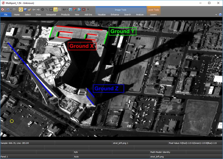
The International Archives of the Photogrammetry, Remote Sensing and Spatial Information Sciences, Volume XLIII-B2-2020, 2020
XXIV ISPRS Congress (2020 edition)
2. METHOD linearity equations (ASPRS, 1980)) uses a calibration matrix:
f 0 cx
The first step in recovering camera models is to select a co- K = 0 f cy
ordinate system. A right-handed, orthogonal coordinate system 0 0 1
should be chosen, for which ground-parallel lines are observ-
able in all images. The conventions of this work are illustrated On the diagonal of K, f represents the focal ratio, in units of
in Figure 1, with ground axes chosen so that in the image per- pixels (the ratio between the focal length and the size of an in-
spective, X will be to the right, Y will be up, and Z will be dividual pixel on the focal plane). PP=(cx , cy ) are the image
most into the camera. The image axes x, y are also indicated coordinates of the principal point (where imaging rays are per-
in parallel in ground space. The image plane is shown in pos- pendicular to the focal plane). K summarizes the calibration or
itive, in front of the focal center (rather than behind C in mir- ‘interior orientation’ of the camera.
ror image). The perpendicular line segment from image plane
‘principal point’ (cx , cy ) to C is the focal length f , in units of The pose or ‘exterior orientation’ is captured in a rotation-
pixels. Image z , out of the camera, completes a right-handed translation matrix
orthogonal system with x and y . Camera rotation matrix R de-
Rt = R|t ,
scribes the rotation between XY Z and xyz .
where R is a 3 × 3 rotation matrix, and t is the 3 × 1 focal
center, in the camera’s xyz frame of reference (note how the
image axes in Figure 1 are paralleled in ground space); if the
camera position in ground scene coordinates is (CX , CY , CZ ),
then t = −RC and C = −R0 t.
Multiplied together, K · Rt is the ‘camera matrix.’ The projec-
tion of ground coordinates into image space is
X
x
y = K · Rt Y
Z (1)
w
1
The 3-dimensional ground coordinates of a scene point
Figure 1. The scene has right-handed axes X, Y, Z, with Z most (X, Y, Z) are augmented with a fourth homographic scale co-
into the image, and X and Y projecting into image space as ordinate of 1, and after application of the 3 × 4 camera mat-
nearly right and up. The image axes x and y are right and down rix, the output is an image coordinate, also augmented with a
from the upper-left of the image, can be seen paralleled in homographic scale. The actual 2D image coordinate to which
ground space. Image z is out of the camera. the ground coordinate projects is then (x/w, y/w). This ho-
mographic unscaling is well-defined everywhere except for the
camera center, which is the only point that yields w = 0. Points
3D points in the scene will be indicated with capital coordin- behind the camera yield w < 0.
ates like (X, Y, Z), and 2D image coordinates (pixels from the
image upper-left corner) will be indicated like (x, y). It is con- 2.2 Vanishing Point Determination
venient to present coordinates as row-vectors in inline text, but
context may dictate they are actually used as column-vectors. If lines in any ground axis direction are not parallel in image
space, all lines corresponding to that axis converge to a vanish-
It is possible to observe the origin and lines parallel to the X , ing point. Depending on the range and the relationship of the
Y , and Z ground axes, as they appear in perspective in 2D im- camera focal plane to ground axes, an image may exhibit van-
age coordinates. In long-range imagery (essentially infinite fo- ishing points for 0, 1, 2, or 3 dimensions. The most general
cal length), ground-parallel lines will also be parallel in image case is 3-point perspective (3PP), which has all three vanishing
space. In close-range imagery, ground-parallel lines will con- points (VPX, VPY, and VPZ); the scope of this paper does not
verge to vanishing points. In either case, the configuration of permit full treatment of 2-point and 1-point perspective, but the
ground-space lines parallel to coordinate axes, as projected into principles are similar, and the reader is referred to (Williamson,
2D vectors in image space, uniquely determine the interior ori- Brill, 1990). Long-range also generalizes 3PP, in the absence
entation (focal length and principal point) and relative exterior of vanishing points.
orientation (viewing direction and orientation) of the camera
with respect to the chosen coordinate system, leaving a degree For determining the image coordinates of vanishing points, if
of freedom of unknown scale, or equivalently, unknown range only two line segments are provided, the vanishing point must
from the camera to the ground origin. Additional inputs such be estimated simply as the intersection of the line segments ex-
as scale bars, or known/assumed focal ratio or range, suffice to tended. Use of multiple line segments per axis adds redundancy
determine a complete pinhole camera. and allows averaging down of error. Due to camera imperfec-
tions and measurement error, multiple vanishing lines will not
intersect in a unique point. When a particular pair of vanishing
2.1 Camera Matrix
lines are very nearly parallel, measurement error can tilt them
so that their intersection is in the opposite direction. Measuring
The standard (Hartley, Zisserman, 2003) matrix representation as many vanishing lines as possible increases the possibility of
of a projective camera (equivalent to the photogrammetric col- this problem. This work uses a least-squares solution for the
This contribution has been peer-reviewed.
https://doi.org/10.5194/isprs-archives-XLIII-B2-2020-487-2020 | © Authors 2020. CC BY 4.0 License. 488The International Archives of the Photogrammetry, Remote Sensing and Spatial Information Sciences, Volume XLIII-B2-2020, 2020
XXIV ISPRS Congress (2020 edition)
location of the vanishing point, from all of the measured line
segments simultaneously (Williamson, Brill, 1989), rather than
from individual pairs, allowing use of as many vanishing lines
as possible, for highest redundancy and accuracy.
Figure 2. (a) Parallel line segments extend to vanishing lines
which intersect at vanishing points. (b) The principal point is
located at the center of the vanishing point triangle, and vectors
∆X , ∆Y , ∆Z toward the vanishing points partially determine
the rotation matrix. Figure 3. The ‘Perspective Pyramid’ is formed with the
vanishing point triangle as the base, and the apex ‘behind’ or
‘above’ the principal point. The apex is at a height such that all
2.3 Principal Point and Focal Length three sides are right triangles, and that height is the focal length
f . 3D image space vectors Rx , Ry , Rz from CS to the
The geometry of 3PP is often described using a ‘Perspective vanishing points form the rotation matrix.
Pyramid’ (See Figure 3). The base of the pyramid is the tri-
angle formed by the three vanishing points. The principal point
(PP=(cx , cy ) in calibration matrix K ) can be found at the ‘cen- Labelling the individual elements of Rt from (1), we can pro-
ter’ of the triangle – the intersection of the three altitudes (lines ject X -axis ground coordinate (X, 0, 0) into image space as fol-
perpendicular the triangle sides, and through the opposite ver- lows:
tices), as shown in Figure 2. x
X
Rx Rxy Rxz tx
f 0 cx
If the 2D image plane is augmented with a z dimension ortho- 0 f cy Ryx Ryy Ryz ty 0 (3)
0
gonal to the image plane (out of the camera towards the scene), 0 0 1 Rzx Rzy Rzz tz
1
then the focal center of camera station lies directly ‘above’ or x x
‘behind’ PP=(cx , cy ) at CS=(cx , cy , −f ). Edges from CS to all f (XRx + tx ) + cx (XRz + tz )
three vanishing points constitute the Perspective Pyramid. All = f (XRyy + ty ) + cy (XRzx + tz ) (4)
three angles between the edges emanating from the apex to- XRzx + tz
x
wards the vanishing points are right angles, and the line from
f Rx + tx /X c
CS to the principal point is perpendicular to the vanishing point ≡ x x + x (5)
Rz + tz /X Ry + ty /X cy
triangle and the whole image plane.
By definition, VPX is limX→∞ of (5), so:
The vanishing point triangle and the principal point at its cen-
f Rxx
ter, can be estimated solely from ground-parallel line segments VPX = x + PP
which converge in image space. The height f of the Perspective Rzx Ry
Pyramid is then determined by the constraint of right angles at
the apex. (Williamson, Brill, 1990) provide a geometric method At this point, Rzx is still unknown, but since
for determining f , by rotating one right-triangular face of the
Rxx
Perpsective Pyramid into the image plane, and using geomet-
x = k(VPX − PP) (6)
rical construction to determine the distance between the prin- Ry
cipal point and CS.
for some constant k, the first two rows of Rx form a vector
Alternatively, f can be solved for algebraically using the ortho- parallel to VPX-PP. Similarly, the first two elements of rotation
gonality constraint, for instance: matrix columns Ry and Rz are parallel to VPY-PP and VPZ-PP.
[(V P X, 0) − (cx , cy , f )] · [(V P Y, 0) − (cx , cy , f )] = 0 (2) The elements in the third row of R are determined by ortho-
gonality constraints (Ri · Ri = 1, Ri · Rj6=i = 0). As shown
Equation (2) can be solved for f using any two vanishing points. in Figure 3, the 3D vectors from the camera station to the van-
ishing points are mutually orthogonal since they are the rays
of the apex of the Perspective Pyramid, so it is clear that aug-
2.4 Solving for Orientation menting each (Rx∗ , Ry∗ ) with a third dimension of f , and then
unitizing, will yield three orthogonal columns for R which re-
The orientation of the camera is determined by forming rotation tain the property that, for each column, the first two elements
matrix R from the 3D vectors from the CS to the vanishing form a vector parallel to a vanishing direction. (Caprile, Torre,
points. 1990) uses a similar analysis to determine the relative rotation
This contribution has been peer-reviewed.
https://doi.org/10.5194/isprs-archives-XLIII-B2-2020-487-2020 | © Authors 2020. CC BY 4.0 License. 489The International Archives of the Photogrammetry, Remote Sensing and Spatial Information Sciences, Volume XLIII-B2-2020, 2020
XXIV ISPRS Congress (2020 edition)
of the second image in a stereopair to the first. endpoints of line segments (at best 0.1 pixels). In long-range
cases like this, it is not critical to know the exact focal length;
Once R is known, orientation angles ωφκ can be determined an arbitrarily long focal length that produces practically-parallel
with standard methods (ASPRS, 1980). ground axes in image space is sufficient, as long as range is also
set to yield appropriate scale. The PP can be arbitrarily chosen
2.5 Solving for Camera Position at the image center, since there are no differences in perspective
when moving around the image, and any required offset can be
At this point, K and R of (1) are determined, and all that yet taken up in camera position.
needs to be solved is camera position t.
Since ground axes appear parallel in image space, there are
Let the observed image coordinates of the ground origin be
no vanishing points to measure, but the common direction of
(ox , oy ), and without loss of generality, temporarily assume that
all lines for the same ground axis serves the same purpose as
the range of the camera is tz = 1. Projecting the ground origin
VP[XYZ]-PP in (6), allowing the same solution for R and ωφκ
into camera space by also substituting X = 0 into (4), it can be
as in section 2.4. To determine each of those VP[XYZ]-PP vec-
seen that t is the solution of
tors from multiple marked lines, line segments can be summed
f tx + cx
o as vectors and then unitized; this naturally weights longer lines
= x more and shorter lines less, which is appropriate because the
f ty + cy oy
same amount of endpoint measurement error in a shorter line
This is a simple solution of two independent equations. segment causes more inaccuracy in determining the true direc-
tion of the vector.
If t = (tx , ty , 1) causes camera KRt to project the ground ori-
gin correctly to (ox , oy ), then it is easily shown that scaling the Camera horizontal offset and range can be determined as in
camera position to t = (rtx , rty , r) continues to project the section 2.5, ensuring that the ground origin projects to the
ground origin into (ox , oy ). This is a last remaining degree of chosen/marked image coordinates, and the camera has the de-
freedom in the range of the camera, or equivalently, the scale of sired scale.
the 3D scene. The position vector can be scaled continuously to
make any particular length in the scene match any known or as- 2.8 Monte Carlo Determination of Covariance
sumed length. In addition, given camera position t in the cam-
era’s frame of reference, the camera’s position in the ground
All of the calculations above (vanishing points, determination
frame of reference can be as C = −R0 t.
of PP and f from vanishing points, determination of attitude
from PP and the vanishing points, and horizontal shift and range
2.6 2-Point Perspective and 1-Point Perspective
adjustment to match origin and scale) are subject to error, tra-
cing back to measurement error at the endpoints of the line
The scope of this article does not permit a full treatment of 2-
segments which must be extended and intersected to locate the
Point and 1-Point Perspective. They can be handled with tech-
vanishing points. In a real-world photographic scene, however,
niques similar to 3PP, except that they require additional in-
pixel quantization and viewing interpolation limit the accuracy
formation to compensate for additional degrees of freedom. For
of human image coordinate measurement to no better than 0.1
instance 3PP is ambiguous only in scale, but 2PP has a degree
pixels, in optimum conditions. Thus, it is desirable to propag-
of freedom in one orientation angle. A photograph taken with a
ate this significant source of error into the space of the resulting
perfectly horizontal camera results in vertical ground lines be-
camera parameters.
ing parallel in image space, so vanishing point VPY retreats
to infinity. In this limiting situation, PP as the center of the
triangle has moved to a point on the horizon between finite van- This is done using a Monte Carlo simulation.2 Given a set of
ishing points VPX and VPZ; but where exactly PP belongs on line segment endpoint coordinates, and an estimate3 of meas-
that horizon cannot be determined without knowledge of the urement error σ , the endpoints are all randomly perturbed using
orientation angle of some vertical or horizontal line segment. a gaussian N (0, σ) distribution, and all of the calculations re-
Typically, this degree of freedom is resolved by constructing a peated with the perturbed measurements, yielding one sample
square around a known circular object in a principal plane (such – a 9-vector of camera parameters (f, cx , cy , ω, φ, κ, tx , ty , tz ).
as a wheel or a manhole cover), and a 45-degree diagonal drawn The perturbation and calculation are repeated many times, and
across the square. (Williamson, Brill, 1990) provides geometric the empirical 9×9 joint variance-covariance matrix is computed
contructions that use the line segment of known orientation to for all of the samples.
precisely locate PP on the VPX-VPZ horizon.
Two notes are in order: First, because a measurement error
2.7 Long-Range Camera Determination in the direction of the line segment has no effect on the line
segment’s extension or the solution of vanishing points, all
Recall that the apex of the Perspective Pyramid is the meeting of gaussian errors are applied in the direction perpendicular to
three right angles (Figure 3). Increasing the focal length – while the line segments. Second, the computed covariance matrix is
maintaining the apex’s rigid cluster of right triangles – causes completely dense, capturing important correlation information
the vanishing points that form the base of the pyramid to retreat
2 From the Latin Monte=Mountain, Carlo=Carl, as in “Even Carl
further outward, away from the finite extent of image space en-
Friedrich Gauss would consider an analytical solution to be mountain-
compassed by the image. As a result, ground lines parallel to
ously hard.” A modern equivalent would be “I can’t be bothered to do it
the XYZ axes, projected into image space, become nearly par- analytically.”
allel when viewed from within the bounds of the image. With 3 Measurement error can be assessed by repeatedly moving and re-
a long enough focal length, ground-parallel lines are practic- placing an endpoint, and computing the sample variance of the resulting
ally parallel in image space – within human ability to locate coordinates.
This contribution has been peer-reviewed.
https://doi.org/10.5194/isprs-archives-XLIII-B2-2020-487-2020 | © Authors 2020. CC BY 4.0 License. 490The International Archives of the Photogrammetry, Remote Sensing and Spatial Information Sciences, Volume XLIII-B2-2020, 2020
XXIV ISPRS Congress (2020 edition)
between camera parameters. The resulting dense parameter co- 3. RESULTS
variance matrix can be used by both for propagation of men-
suration error into ground space for mono or stereo exploita- 3.1 Simulated Images
tion, or as an input to least-squares bundle-adjustment, ensuring
that all parameter corrections are assigned rigorously meaning- Synthetic images are generated of a 1m cube, and camera para-
ful weights. meters are varied to understand their effect on the accuracy
of the resection process. The baseline image is seen in Fig-
2.9 Implementation ure 4. The cube is positioned from ground (0,0,0) to (1,1,1),
and is rendered into a 1000x800 image using a camera set up
as f = 1000pix, center PP, ω = 10◦ , φ = 20◦ , κ = 30◦ ,
The method of camera recovery outlined above was implemen-
from a position of (CX , CY , CZ ) = (2, − 12 , 5) (this is t ≈
ted in Python.
(−0.33, 0.24, 5.39) in the camera’s frame of reference).
The inputs for a 3PP resection are:
• A line segment (two pairs of image coordinates of end-
points) to serve as a scale bar along the X axis, and the
ground length l of that scale bar.
– The first endpoint of the scale bar is taken to be the
ground origin (0, 0, 0).
– The other end point is (l, 0, 0).
Figure 4. Baseline image of a 1m cube. Edges are color-coded
– This could be generalized to be a scale bar between by their axis direction, XYZ∼RGB. The origin is circled, and
any specified 3D ground coordinates.
the square around the opposite corner (1,1,1) illustrates the
extent of Figure 5.
• Image coordinate endpoint pairs for at least two line seg-
ments in each axis.
Monte Carlo covariance estimation yields a 9 × 9 covariance
matrix. To distill that into a more succinct metric of error, par-
• Measurement sigma and number of iterations for Monte
tial derivatives are computed of the ground-to-image projection
Carlo covariance estimation.
function, with respect to the sensor parameters, at the opposite
cube corner (1,1,1). The 9 × 9 covariance matrix in sensor para-
The outputs are: meter space is reduced to image space by outer-multiplying it
by the 2 × 9 partial-derivative matrix, yielding 2 × 2 covariance
in image space. For the baseline cube case, a reasonable 0.3
• Vanishing point coordinates VPX, VPY, VPZ. pixel measurement error sigma thus yields image space error:
0.4088 −0.4602
• Camera parameters PP, f , orientation angles ω, φ, κ, and (7)
−0.4602 2.2898
camera position (CX , CY , CZ ).
Figure 5 shows a scatterplot of 1000 reprojections, illustrating
• 9 × 9 covariance matrix estimated by Monte Carlo simu- the magnitude of covariance matrix (7). Note the center ellipse
lation. √
captures 1σ error, with semimajor
√ radius σy = 2.2898 ≈
1.54, semiminor radius σx = 0.4088 ≈ 0.64, and tilt due to
nonzero covariance/correlation. The outer two ellipses enclose
For 2PP cases, the input also requires a pair of endpoints of a
2σ and 3σ error regions.
line segment known to be 45 degrees in the XY plane – again,
this could be generalized to a line segment of any known angle
Note that, while the scatter in Figure 5 is generated by dir-
in any known plane, but is most likely the diagonal of a square
ectly exercising the perturbed cameras, the ellipses are gener-
circumscribed around the circular rim of a wheel.
ated from the Monte Carlo camera parameter covariance, and
partial derivatives computed with the unperturbed camera. The
For long-range cases, a minimum of only one line segment per coherence of the ellipses with the scatter is evidence of correct-
axis is required. A long-range resection also accepts the desired ness for the Monte Carlo method.
long focal ratio.
The area of the 1σ ellipse is 1.54 · 0.64 · π ≈ 1 × π – equival-
The Python script is sufficiently quick to enable relatively large ent to a circle of radius 1, so we will use this metric (the geo-
Monte Carlo simulations, even single-threaded. Without Monte metric mean of the x and y error sigmas) as a 1-dimensional
Carlo covariance estimation, a single camera solution is prac- summary of the error in the process, and call it an approxim-
tically instantaneous. For analytical cube tests (four ground- ately 1-pixel reprojection error (a serendipitously round value)
parallel cube edges for each of the three vanishing points), the for the baseline case.
covariance matrix for 1000 samples can be generated on a Len-
ovo P50 laptop with an Intel Core i7 2.7GHz processor, in 1.30 Starting from the baseline configuration described above, vari-
seconds. ous settings are adjusted to examine their effect on accuracy.
This contribution has been peer-reviewed.
https://doi.org/10.5194/isprs-archives-XLIII-B2-2020-487-2020 | © Authors 2020. CC BY 4.0 License. 491The International Archives of the Photogrammetry, Remote Sensing and Spatial Information Sciences, Volume XLIII-B2-2020, 2020
XXIV ISPRS Congress (2020 edition)
or halving the number of line segments per axis exerts less of
an effect on reprojection error than line segment length, ranging
from 0.72 to 1.45 pixels of error.
The line labeled ‘Optimum’ uses the most error-reducing value
for each of curves in the Figure: σ = 0.1 pixel measurement
error, and ten vanishing line segments per axis, each of ground
length 2.5m. This most-optimistic configuration yielded a re-
projection error of 0.097 pixels.
3.2 Real Images
3.2.1 Close-Range Example: Multi-View from Images of
Different Volkswagen Things The Volkswagen Thing is per-
fectly suited to this analysis, with easily visible exterior lines in
three orthogonal directions. Two VW Things, and vanishing
lines, are displayed in Figure 7. In total, 35 images of VW
Things were chosen from the internet (Wikimedia commons,
2020). Images from the right side of the car were flipped to
simulate an equivalent image of the left side of the car. Cam-
eras were resected for each according to the methods above.
Scale was set to a 768mm door-to-door distance (based on a
Figure 5. 1000 reprojections using Monte Carlo perturbations of spec value of 727mm for the width of the door opening in the
the baseline model. The grid lines are individual pixels. The body, and scaled up using a 1PP image). The cameras were
ellipses are 1σ, 2σ, and 3σ ellipses for covariance matrix (7). marked with min/avg/max 15/26/39 vanishing lines and Monte
Carlo covariance took 1.4/3.4/11.0 seconds.
Figure 6 presents the effect on reprojection error of these devi-
ations from the baseline setup. Three different error response
curves are presented with a unified X axis, which indicates the
multiple of the baseline value that is used for the corresponding
parameter. The baseline case is indicated at the intersection of
the three curves (all three parameters at 1.0×baseline).
Figure 7. Two Volkswagen Things, viewed in 3-point
perspective, with ground-parallel lines marked. Z is chosen as
the dimension most into the image, completing a right-handed
coordinate system with X towards image-right, and Y towards
Figure 6. Simulated reprojection error for various configurations image-up.
of measurement error and vanishing line segments. The error
depicted in Figure 5 is the baseline case at the intersection of the
three curves. Benchmark measurements for comparison are detailed in Table
1. It was not possible to identify both endpoints of each bench-
mark distance in all 35 images, because of perspective (images
Obviously, increased measurement error leads to increased re- from the back of the car cannot see the windshield in the front),
projection, which is illustrated in the increasing curve in Fig- non-stock parts (custom bumpers or no bumpers at all), config-
ure 6. Cutting measurement error to 1/3 of the baseline value uration (windshield folded down), blurriness, etc. The number,
(to σ = 0.1 pixels) decreases reprojection error from 1.0pix to average, and sigma of estimates for each benchmark are de-
0.32pix, and tripling to σ = 0.9 more than triples the reprojec- tailed in Table 2. The L1 and L2 door width measurements
tion error to 3.14. are almost proxies for the door-to-door distance (including the
pillar between the doors) that was used to set the scale of the
The natural 1m length of the vanishing line segments is ranged project; but the door-to-door scale bar was established between
from 0.25 to 2.5m; just as a rifle offers smaller targeting error the bottom corners of the doors, and the L1 and L2 door widths
than a pistol, longer line segments yield less reprojection error were measured across the top of the doors.
than shorter; bracketing the 1pix baseline error with 2.1pix for
0.25m line segments, to 0.5pix for 2.5m segments. Lengths (distances along the chosen X-axis) and heights (Y-
axis) are measured by simply projecting image coordinates to a
The baseline number of line segments per vanishing point is the depth of Z = 0 in the ground scene, and computing the distance
four in each dimension that are naturally present in a cube. This between the ground points.
number is tested from the bare minimum of 2 (0.5×baseline)
to 10 (2.5×baseline), demonstrating that measuring additional Widths (distances along the Z-axis) require an assumed ground
vanishing line segments also reduces error; however, doubling X value for the desired line. First, the desired line is extended in
This contribution has been peer-reviewed.
https://doi.org/10.5194/isprs-archives-XLIII-B2-2020-487-2020 | © Authors 2020. CC BY 4.0 License. 492The International Archives of the Photogrammetry, Remote Sensing and Spatial Information Sciences, Volume XLIII-B2-2020, 2020
XXIV ISPRS Congress (2020 edition)
Label mm Description
L1 727 Max width of door opening (front)
L2 727 Max width of door opening (rear)
L3 3780 Length of car (bumper to bumper)
H1 345 Distance between door hinges (front)
H2 345 Distance between door hinges (rear)
W1 1495 Width of car body
W2 1353 Inner width of windshield frame (bottom)
W3 1270 Inner width of windshield frame (top)
Table 1. Benchmark VW Thing dimensions, categorized as
Lengths, Heights, and Widths.
image space. Then the Y-axis ground line (X, 0, 0) + c(0, 1, 0)
is rendered in the image, and the intersection of the two lines de-
termines the X, Y values of the Z-axis line in question. The ex-
tended line is traversed to determine the values Zlo , Zhi nearest
the endpoints of the desired line segments, from which we com- Figure 8. Monoscopic length (X-axis) estimates, in mm. L1 and
pute the desired length. L2 use the left axis, L3 the right. Benchmark values are indi-
cated with —, and triangulated multiscopic estimates with ×.
Known N Avg Err% Sig Multi Err%
L1 (727) 28 726 0.13 7.4 726 0.13
L2 (727) 20 719 1.10 13.1 726 0.13
L3 (3780) 30 3827 1.24 86.9 3730 1.23
H1 (345) 31 353 2.31 8.1 351 1.73
H2 (345) 31 354 2.60 9.5 351 1.73
W1 (1495) 15 1496 0.07 53.9 1520 1.67
W2 (1353) 15 1393 2.96 37.0 1393 2.95
W3 (1270) 10 1283 1.02 26.9 1294 1.89
Table 2. Comparison of monoscopic (average) and multiscopic
VW Thing measurements.
The 35 resected cameras were then formed into Frame sensor
models for exploitation in SOCET GXP geospatial intelligence
software, and then bundle-adjusted in Multi Sensor Triangula-
tion (MST). The bundle adjustment involved 41 tie points. The
two endpoints of the chosen scale were set to 3D control points
at ground positions (0,0,0) and (0.768,0,0). All of the endpoints
of the 8 benchmark measurements in Table 1 were included as Figure 9. Monoscopic width (Z-axis) and height (Y-axis)
tie points. The remaining 41-2-16=23 tie points were distrib- estimates, in mm. Widths use the left axis, heights the right.
uted around the vehicle and along all three dimensions. All
Benchmark values are indicated with —, and triangulated
nine camera parameters (three position, three orientation, fo-
multiscopic estimates with ×.
cal length and principal point) were adjusted for all images,
weighted by the Monte Carlo covariance at σ =0.3pixels. The
aposteriori ground locations of the tie points were used to com- candidates for stereo exploitation. The published height of the
pute the distances in Table 2. Stratosphere Tower is 350.2m.
Since Table 2 lists only average values of monoscopic meas- The origin is chosen to be at a point that can reasonably be as-
urements, the spread of all the measurements are illustrated in sumed to be at the same elevation as the base of the tower. Ac-
Figures 8 and 9. tual WorldView-1 design parameters are ignored, and instead,
as mentioned above, an arbitrarily long focal length of 1000mm
3.2.2 Long-Range Example: Stereo from Chips of World- is used together with a pixel size of 1µm, for a focal ratio of
View-1 Satellite Imagery Small extents of imagery in Las 106 pixels. The principal point is set arbitrarily (without loss of
Vegas, around the Stratosphere Tower were chipped out generality) at the center of the chip.
of WorldView-1 satellite imagery, stripping all collection
metadata, and yielding dumb images with no geolocation or Orientation is solved for using the technique in section 2.4. The
perspective information. parallel vectors in each axis direction are used in place of vec-
tors from the principal point towards the vanishing points. Sec-
Three ground axis directions were chosen, corresponding to tion 2.5 is used to solve for camera horizontal offsets tx , ty .
strongly visible features assumed to be orthogonal (given how Range tz is adjusted so that horizontal scale matches meas-
buildings are most usually constructed), as depicted in Figure urements of the area from online maps (the two chips require
10. The Z dimension of interest is most clearly visible in the different ranges, since they were collected at different points
tower, but also in other vertical building edges. The other chip along the orbit of the WorldView-1 spacecraft, with different
is not shown, but the tower (and all vertical structures) exhibit a slant ranges to the scene). Given a proper solution for the cam-
layover angle to the right, so the two images together are good eras, vertical scale will thus also be correct.
This contribution has been peer-reviewed.
https://doi.org/10.5194/isprs-archives-XLIII-B2-2020-487-2020 | © Authors 2020. CC BY 4.0 License. 493The International Archives of the Photogrammetry, Remote Sensing and Spatial Information Sciences, Volume XLIII-B2-2020, 2020
XXIV ISPRS Congress (2020 edition)
REFERENCES
ASPRS, 1980. Manual of Photogrammetry, 4th ed. ASPRS,
Falls Church, VA.
BAE Systems Inc., 2019. SOCET GXP Software, version
4.4.0.3. www.GeospatialExploitationProducts.com.
Caprile, B., Torre, V., 1990. Using Vanishing Points for Camera
Calibration. Intl J of Computer Vision, 4, 127-140.
DigitalGlobe, 2008. Stereo WorldView-1 imagery of Las Vegas,
collected 2018-02-11. DigitalGlobe.com.
Durrant-Whyte, H., Bailey, T., 2006. Simultaneous Localiza-
tion and Mapping (Parts I,II). IEEE Robotics & Automation
Magazine, 13(2), 99-117.
Figure 10. Stratosphere Tower, imagery chipped from
Flickr user jacksnell11707, 2012. “1973 Volks-
WorldView-1 and marked with chosen ground origin (yellow
wagen Thing 4 Door Convertible 2”. flickr.com/
marker) and coordinate axes. A second chip is also used,
photos/jacksnell707/7068809657.
collected from a perspective such that the layover of the tower is
to the right. Flickr user squeakymarmot, 2008. “powder blue VW thing”.
flickr.com/photos/squeakymarmot/3178413638/.
The height of the tower is measured in each of the resected
Forsyth, D., Ponce, J., 2003. Computer Vision: A Modern Ap-
images, using SOCET GXP geospatial intelligence software’s
proach. Prentice Hall.
monoscopic height measurement tool. In the image with the
left-leaning tower (shown in Figure 10), the height is measured Hartley, R., Zisserman, A., 2003. Multiple View Geometry in
at 371.9m, an error of +6.20%. In the image with the tower Computer Vision. 2 edn, Cambridge University Press, Cam-
leaning right (not depicted), the height of the tower is signific- bridge.
antly underestimated at 309.5m (-11.6%).
Magee, M. J., Aggarwal, J. K., 1984. Determining Vanishing
After both long-range cameras are solved for, they are bundle- Points from Perspective Images. Computer Vision, Graphics,
adjusted together in SOCET GXP geospatial intelligence soft- and Image Processing, 26, 256-267.
ware MST to improve stereo alignment for 3D exploitation. To
ensure the images align around a common 3D model, and not Saxena, A., M. S., Ng, A. Y., 2008. Make3d: Depth perception
just on the ground plane, tie points are included at a wide range from a single still image. In: AAAI Conference on Artificial
of heights; particularly at the tip of the tower’s spire, and around Intelligence, 1571-1576.
the observation deck. After bundle-adjustment, the tip of the
spire is at Z=362.92m – that is, above the arbitrarily-chosen Ullman, S., 1979. The interpretation of structure from motion.
origin at street level. That is 3.6% above the known height of Proc Royal Society of London, 203(1153), 405-426.
350.2m. Part of that error might be extra height delta to the Wikimedia commons, 2020. Category:Volkswagen Type
arbitrary origin, part will be from imperfect camera pose and 181, (Accessed 2020-04-18). commons.wikimedia.org/
scale. wiki/Category:Volkswagen Type 181.
4. CONCLUSION Williamson, J. R., Brill, M. H., 1989. Dominant Geometry
Combinations of Two- and Three-Point Perspective in Close-
In this work, camera models are developed for images using or- Range Applications. Photogrammetric Engineering and Re-
thogonal ground axes evident in the scene. The technique gen- mote Sensing, 55(2), 223-230.
eralizes to various close-range cases, in which ground-parallel Williamson, J. R., Brill, M. H., 1990. Dimensional Analysis
lines converge to vanishing points in image space, and long- from Perspective: A Reference Manual. ASPRS, Falls Church,
range cases, in which ground-parallel lines are also parallel in VA.
image space. The joint, correlated covariance of camera para-
meters is estimated with a Monte Carlo method based on meas-
urement uncertainty of the user-marked line segment endpoints.
The 3-point perspective case is examined with synthetic images,
verifying that the estimated Monte Carlo covariance is consist-
ent with simulated error. The techniques are then applied to
real images. In the close-range situation, thirty-five 3-point per-
spective images of different Volkswagen Thing automobiles are
used, and various recovered dimensions are within 3% or bet-
ter of the published specifications. A long-range case is con-
sidered using overhead views of the Stratosphere Tower in Las
Vegas, recovering the height of the tower to within 3.6% of the
published value. These techniques bear much promise for 3D
measurement from images of unknown provenance.
This contribution has been peer-reviewed.
https://doi.org/10.5194/isprs-archives-XLIII-B2-2020-487-2020 | © Authors 2020. CC BY 4.0 License. 494You can also read