Instruction Manual PSx3xxPL - halstrup walcher
←
→
Page content transcription
If your browser does not render page correctly, please read the page content below
Instruction Manual PSx3xxPL

                       Instruction Manual
                       PSx3xxPL

                                                 halstrup-walcher GmbH
                                                 Stegener Straße 10

                                                 D-79199 Kirchzarten

                                                 Tel.:       +49 (0) 76 61/39 63-0
                                                 Fax:        +49 (0) 76 61/39 63-99

                                                 E-Mail:     info@halstrup-walcher.com
                                                 Internet:   www.halstrup-walcher.com

Document 7100.005424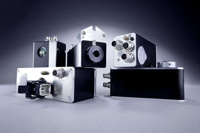
Instruction Manual PSx3xxPL

       Table of Contents
1   Safety precautions........................................................................................................ 4
    1.1     Appropriate use ................................................................................................. 4
    1.2     Shipping, assembly, electrical connections and start-up .................................... 4
    1.3     Troubleshooting, maintenance, repairs, disposal ............................................... 4
    1.4     Symbols ............................................................................................................. 5
2   Device Description ....................................................................................................... 5
    2.1    Features ............................................................................................................ 5
    2.2    Installation ......................................................................................................... 6
    2.3    Disassembly ...................................................................................................... 7
    2.4    Powering the device........................................................................................... 8
    2.5    Pin assignment .................................................................................................. 8
    2.5.1 Supply voltage connector ................................................................................... 8
    2.5.2 Round socket for bus ......................................................................................... 8
    2.5.3 1 Hybrid bushing for supply and bus .................................................................. 9
    2.5.4 Connector for jog keys ....................................................................................... 9
    2.5.5 Connector-option -2Y-........................................................................................ 9
    2.5.6 Electrical grounding ........................................................................................... 9
    2.6    Setting the device address ................................................................................. 9
    2.7    LEDs ................................................................................................................ 10
    2.8    Start-up ............................................................................................................ 10
    2.8.1 Positioning run ................................................................................................. 11
    2.8.2 Manual run ....................................................................................................... 12
    2.8.3 Restoring the factory settings (without control system) .................................... 12
    2.9    Powerlink interface........................................................................................... 12
    2.9.1 Table of entries implemented from object dictionary ........................................ 13
    2.9.2 Table of rated speed and torque values for various models of gears ............... 19
    2.9.3 PDO definition.................................................................................................. 21
    2.9.4 Detailed description of the status bits ............................................................... 21
    2.9.5 Detailed description of control bits ................................................................... 24
3   Sequence of positioning ............................................................................................ 25
    3.1   Positioning run with loop .................................................................................. 25
    3.2   Positioning run without loop ............................................................................. 26
4   Specials ....................................................................................................................... 27
    4.1    Speed, acceleration and deceleration .............................................................. 27
    4.2    Maximum starting torque and maximum torque ............................................... 27
    4.3    Response of drive in case of block ................................................................... 27
    4.4    Response of drive in case of manual displacement (readjustment) .................. 28
    4.5    Calculating the absolute physical position ........................................................ 28
    4.6    Using position scaling factors to set the spindle pitch....................................... 30
    4.7    Drag error monitoring ....................................................................................... 31
    4.8    Drag error correction ........................................................................................ 31
    4.9    Abort run when the master fails........................................................................ 31
    4.10   Devices with “Jogkeys” option .......................................................................... 32
    4.11   Devices with optional snap brake ..................................................................... 33
    4.12   Devices with optional holding brake ................................................................. 34
    4.13   Reference runs ................................................................................................ 35
    4.14   Reverse drive................................................................................................... 35
5   Technical Data ............................................................................................................ 36
    5.1    Ambient conditions........................................................................................... 36
    5.2    Electrical Data.................................................................................................. 36
    5.3    Physical data ................................................................................................... 37
6   Certificate of Conformity ............................................................................................ 38

                                                                2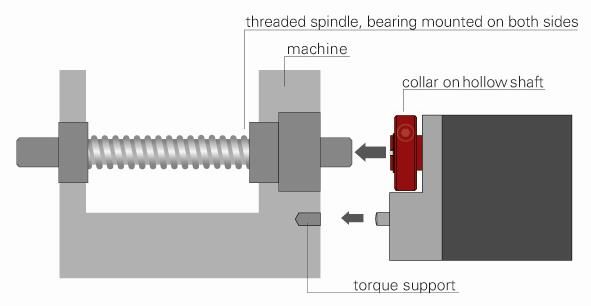
Instruction Manual PSx3xxPL
Purpose of instruction manual
This instruction manual describes the features of the PSx3xxPL positioning system
and provides guidelines for its use.
Improper use of these devices or failure to follow these instructions may cause injury
or equipment damage. Every person who uses the devices must therefore read the
manual and understand the possible risks. The instruction manual, and in particular
the safety precautions contained therein, must be followed carefully. Contact the
manufacturer if you do not understand any part of this instruction manual.
Handle this manual with care:
It must be readily available throughout the lifecycle of the devices.
It must be provided to any individuals who assume responsibility for operating the
device at a later date.
It must include any supplementary materials provided by the manufacturer.
The manufacturer reserves the right to continue developing this device model without
documenting such development in each individual case. The manufacturer will be
happy to determine whether this manual is up-to-date.
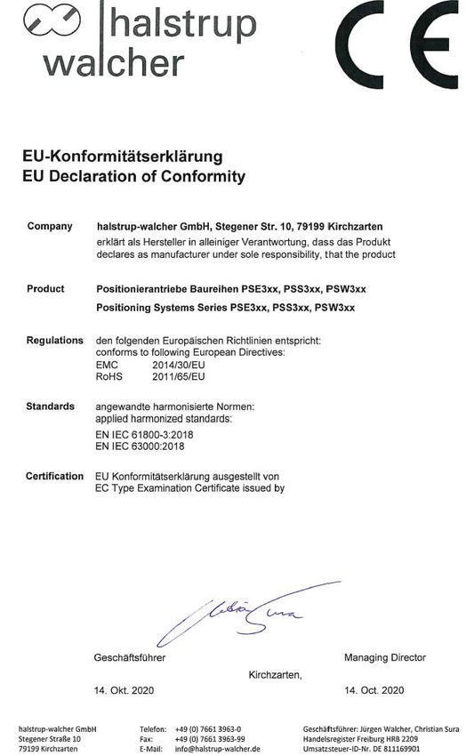
Conformity
This device is state of the art. It complies with the legal requirements of EC
directives. This is shown by the CE mark.
© 2015, 2016, 2017, 2019, 2020, 2021
The manufacturer owns the copyright to this instruction manual. It contains technical
data, instructions and drawings detailing the devices’ features and how to use them. It
must not be copied either wholly or in part or made available to third parties.
3Instruction Manual PSx3xxPL
1 Safety precautions
1.1 Appropriate use
Positioning systems are especially suitable for automatically setting tools, stops or
spindles for wood-processing equipment, packing lines, printing equipment, filling
units and other types of special machines.
PSx3xx positioning systems are not stand-alone devices and may only be used
if coupled to another machine.
Always observe the operating requirements – particularly the permissible supply
voltage – indicated on the rating plate and in the “Technical data” section of this
manual.
The device may only be handled as indicated in this manual. Modifications to the
device are prohibited. The manufacturer is not liable for damages caused by improper
use or failure to follow these instructions. Violations of this type render all warranty
claims null and void.
1.2 Shipping, assembly, electrical connections and start-up
Assembly and the electrical connections should only be handled by professionals.
They should be given proper training and be authorised by the operator of the facility.
The device may only be operated by appropriately trained individuals who have been
authorized by the operator of the facility.
Specific safety precautions are given in individual sections of this manual.
1.3 Troubleshooting, maintenance, repairs, disposal
The individual responsible for the electrical connections must be notified immediately
if the device is damaged or if errors occur.
This individual must take the device out of service until the error has been corrected
and ensure that it cannot be used unintentionally.
This device requires no maintenance.
Only the manufacturer may perform repairs that require the housing to be opened.
The electronic components of the device contain environmentally hazardous
materials and materials that can be reused. The device must therefore be sent to a
recycling plant when you no longer wish to use it. The environment codes of your
particular country must be complied with.
4Instruction Manual PSx3xxPL
1.4 Symbols
The symbols given below are used throughout this manual to indicate instances when
improper operation could result in the following hazards:
WARNING! This warns you of a potential hazard that could lead to bodily injury
up to and including death if the corresponding instructions are not followed.
CAUTION! This warns you of a potential hazard that could lead to significant
property damage if corresponding instructions are not followed.
INFORMATION! This indicates that the corresponding information is important
for operating the device properly.
Caution! This indicates possible hot surface.
2 Device Description
2.1 Features
The PSx3xx positioning system, an intelligent, compact, complete solution for
positioning auxiliary and positioning axes, consists of an EC motor, gear power
amplifier, control electronics, absolute measuring system and EtherCAT interface.
The integrated absolute measuring system eliminates the need for a time-consuming
reference run. Connecting to a bus system simplifies the wiring. A hollow shaft with
adjustable collar makes assembly quite simple. The positioning system is especially
suitable for automatically setting tools, stops or spindles for wood-processing
equipment, packing lines, printing equipment, filling units and other types of special
machines.
PSx3xx positioning systems convert a digital positioning signal into an angle of
rotation.
If the device names are given without the diameter of the output shaft (-8, -
14), the relevant information is valid for all offered output shafts (applies
throughout the document).
‘x’ in the device name stands for a number in the range 0..9. ‘xx’ in the
device name stands for a number in the range 10..999.
5Instruction Manual PSx3xxPL
2.2 Installation
Hollow shaft:
The PSx3xx is mounted on the machine by sliding it with the hollow shaft onto the
spindle to be driven and fixing it with the clamping ring (recommended shaft diameter
8 h9 or 14 h9; tightening torque of the clamping ring screw with 3 mm hexagon
socket: 1.5 Nm).
The depth of the hollow bore is 20 mm. For optimum operation, the pin of
the shaft to be driven should correspond to this depth. Depending on the
operating situation, significantly shorter pins (< 16 mm) may cause
damage to the PSx3xx. When mounting the PSx3xx, it should only be
pushed on until the foam rubber plate lies evenly on the bottom of the
machine or is compressed to approx. half its thickness. Under no
circumstances may the PSx3xx "hard" be screwed to the machine
without an air gap.
The rotation lock is made via the pin (in the picture below the hollow shaft) into a
suitable bore as rotary torque support. This hole must be slightly larger than the
diameter 6 h9 of the pin. An oblong hole or slot with a slightly larger width
(recommended: 6.05...6.10 mm) than the dimension of the pin diameter is optimal.
The backlash when changing the direction of rotation has a direct influence on the
positioning accuracy and can lead to damage to the PSx3xx with very large backlash
(a few mm) due to the impact load.
The PSx3xx must have a little gap on all sides when mounted, as it can
move axially and/or radially during positioning if the hollow shaft and
solid shaft are not 100% aligned. This "staggering" is not a defect of
the PSx3xx and also has no influence on the function, as long as it can
move freely.
6Instruction Manual PSx3xxPL
Versions with higher torques (from 10 Nm):
Here the force connection is made via a feather key DIN 6885-A5x5x12.
The clamping ring is not freely rotatable but consists of two halves, the fixed part of
the hollow shaft and the loose clamping clamp. The keyway is located in the half that
is fixed to the output shaft. When sliding onto the shaft to be driven with the key
inserted, its angular position must be aligned with the keyway in the PSx3xx. After
pushing on, the PSx3xx is fixed with the 2 screws in the flexible clamping ring half.
Make sure that both screws are tightened as equally as possible (tightening torque of
the screws with 3 mm hexagon socket: 1.5 Nm).
The information on torque support applies in the same way as described above.
For PSE30x-14, PSE32x-14, PSS30x-14 and PSS32x-14, the position of the anti-
rotation lock can be set at greater distances by unscrewing the base cover, turning it
180° and then screwing it back on. When screwing on, make sure that the seal is
correctly inserted in the floor.
For torques > 5 Nm we recommend to choose the greater distance.
Solid shaft:
The PSx3xx is installed on the machine by mounting the drive to the axis to be driven
using a coupling and an intermediate flange.
Under no circumstances may the housing cover be used for the
purpose of the transmission of force.
Underwater usage of the PSW is not allowed.
Please consider that the device might have
a hot surface during operation!
2.3 Disassembly
To remove the PSx3xx from the shaft, release the clamp (for versions with hollow shaft
the clamping ring) and pull the PSx3xx off the shaft. If possible, the PSx3xx should only
be pulled axially. Excessive bending back and forth can damage the output shaft! For
versions with brake, it is essential to observe the instructions in sections 4.11 and 4.12!
7Instruction Manual PSx3xxPL
2.4 Powering the device
For motor power use a single fuse with max. 3,5 A for each PSx3xx.
For motor power use a single fuse with max. 10 A for each PSE34xx.
For control power you can use a fuse with max. 2,0 A, so it is
possible to power up to 10 units parallel with one fuse.
It is strongly recommended to separate power cables to the PSx3xx
from other power cables that might have dangerous voltage.
2.5 Pin assignment
Please take care that the mating connectors and the used cables
match the connectors in the PSx3xx and are mounted correctly,
in order to achieve the protection class.
2.5.1 Supply voltage connector
connector pattern assignment type
(external top view)
1. +24V motor PSE/PSS:
2. GND motor M12 (A-cod.); 5-pol.
3. +24V control unit PSW:
4. GND control unit M12 (A-cod.);
5. housing/pressure balance 4-pol. with airtube
1. +24V motor PSE34xx:
2. GND motor HAN4A, Harting
3. +24V control unit
4. GND control unit
5. housing/pressure balance
To prevent the ingression of fluids into the PSW-housing during
cooldown, use a special cable with an airtube for pressure
balancing of your PSW
2.5.2 Round socket for bus
connector pattern assignment type
(external top view)
1. TD+(WH/GN, white/green)
2. RD+ (WH/OG, white/orange)
3. TD- (GN, green) M12 (D-cod.); 4-pol.
4. RD- (OG, orange)
Due to the use of 4-pin sockets, only four-wire cables
should be used.
8Instruction Manual PSx3xxPL
2.5.3 1 Hybrid bushing for supply and bus
connector pattern assignment type
(external top view)
1. TD+ 5. GND motor M12 (Y-cod.); 8-pol.
2. TD- 6. GND control unit
3. RD+ 7. +24V motor
4. RD- 8. +24V control unit
2.5.4 Connector for jog keys
connector pattern assignment type
(external top view)
1. +24V output
(=+24V control in supply voltage M8; 4-pol
connector)
2. forward key
3. reverse key
4. ground (= GND control unit)
2.5.5 Connector-option -2Y-
Two Y-coded bushings for bus and control supply
One A-coded connector for motor supply
connector pattern assignment type
(external top view)
1. TD+ 5. +24V control unit M12 (Y-cod.); 8-pol.
2. TD- 6. GND control unit
3. RD+ 7. +24V control unit
4. RD- 8. GND control unit
1. +24V motor
2. M12 (A-cod.); 5-pol.
3. GND motor
4.
5.
2.5.6 Electrical grounding
Next to the connecting plugs there is a M4 stud bolt. It is recommended to connect
the positioning system with a cable as short as possible to the machine base. The
minimum wire cross section therefor is 1.5mm².
2.6 Setting the device address
Removing the protective cap provides access to two rotary switches for setting the
device address at the bus.
The rotary switches indicate the tens and ones places of the address selected.
The delivery setting is 00, i.e. before the first start-up a valid address has to be set.
9Instruction Manual PSx3xxPL
2.7 LEDs
The following LEDs are located under the transparent sealing plug:
P1/P2: green Link/Act LEDs for ports 1 and 2
BS/BE: Powerlink STATUS and ERROR LEDs (green/red; see Powerlink spec.)
V_Motor: The LED is illuminated yellow when power is available to the motor.
Switch configurations:
PSx30x, PSx31x-8, PSx31x-14, PSx33x
PSx32x, PSE31xx,
PSE34xx
Meaning of the LEDs:
1) Each of the ports (P1/P2) has an associated green LED for the “Link” and the
“Activity” state.
For each port the following states are possible:
- Off no connection
- On connection; data transmission inactive
- Flickering with 10 Hz connection; data transmission active
2) Green and red Powerlink LEDs
Powerlink STATUS and ERROR LEDs (green/red; see 2.9 Powerlink interface)
3) The yellow LED “Motor” indicates the supply voltage for the motor:
- Off supply voltage for motor too low or too high
- On supply voltage for motor ok
2.8 Start-up
After the supply voltage has been hooked up, a positioning or manual run can begin
immediately.
For easier support of the devices by configuration tools, the following device
description files are available in the download area at www.halstrup-walcher.de:
- for devices without jog keys: 000002D8_PSx3xxPL.xdd
- for devices with jog keys: 000002D8_PSx3xxPL-V2.xdd
10Instruction Manual PSx3xxPL
2.8.1 Positioning run
- To be able to control the drive with the help of PDOs, it has to be switched to the CN
cycle state “operational”.
- Transfer target value:
- PDO with control word = 0x14 and desired target value
OR
- PDO with control word = 0x10 and target value in SDO #2001
Drive begins run
- Abort run by resetting the release bit:
- PDO with control word = 0x00
OR
- SDO #2024 with value 0x00 (if pre-operational)
- If a new target value is transferred during a positioning run, the device will
immediately proceed to the new target. There will be no interruption if the direction of
rotation does not need to be altered.
- If a manual run is transmitted during a positioning run, the positioning run will be
aborted (speed will be reduced to that of a manual run) and the device proceeds with
the manual run.
The following sequence of steps is also possible:
Starting situation: release has not been set
- Transfer target value:
- PDO with control word = 0x04 and desired target value
OR
- PDO with control word = 0x00 and target value in SDO #2001
- Set release:
- PDO with control word = 0x10
OR
- SDO #2024 with value 0x10 (if pre-operational)
Drive begins run
Where applicable, positioning runs involve a “loop run” which causes the target
position to be reached from a predefined direction. The direction and the length
of the loop run can be set to the desired value with SDO #201F (“length of loop”)
before the run. With SDO #201F the loop run might also be disabled.
Underwater usage of the PSW is not allowed
Setting of control word and target value with the help of SDOs is only possible in
the CN cycle state “pre-operational”.
11Instruction Manual PSx3xxPL
2.8.2 Manual run
- Start manual run (transmit PDO with control word = 0x11 resp. 0x12 or, if pre-
operational, transmit SDO #2024 with value 0x11 resp. 0x12): device begins to run
- End manual run by clearing the manual run command (transmit PDO with control
word = 0x10 or, if pre-operational, transmit SDO #2024 with value 0x10) or by
deasserting release (transmit PDO with control word = 0x00 or, if pre-operational,
transmit SDO #2024 with value 0x00).
- Transferring a target value during a manual run will end the manual run and the
device will immediately move on to the transmitted position (PDO with control word =
0x14 and desired target value). If pre-operational, target value to SDO #2001. The
drive then automatically deasserts the manual run bits in the control word (bits 0 and
1).
2.8.3 Restoring the factory settings (without control system)
It is possible to reset the device to the delivery state even without the presence of a
control system. To do this, carry out the following steps:
1) Switch off the device.
2) Set the address switch to 98.
3) Switch on the device (control and motor supply voltage).
4) The yellow LED now flashes at 10Hz for 10 seconds. If during this time the address
is set to 99, the drive will set all parameters to the factory settings, save them and
move the axle to the centre position.
5) Set the address switch to 00 to complete the delivery state.
6) Switch off the device.
The 10-second period is ended prematurely when a communication is established.
2.9 Powerlink interface
The Powerlink interface is realized according the EPSG standard 301, version 1.2.0:
One send and receive SDO per device
One asynchron send and receive PDO, active by default
Meaning of the LEDs:
1) Each of the ports (P1/P2) has an associated green LED for the “Link” and
the “Activity” state.
For each port the following states are possible:
- Off no connection
- On connection; data transmission inactive
- Flickering with 10 Hz connection; data transmission active
2) The green Powerlink LED “Bus Status” (BS) signalizes the CN cycle state.
- Off NOT_ACTIVE
- Flickering with 10 Hz BASIC_ETHERNET
- Single flashing with 0.8 Hz PRE-OPERATIONAL_1
- Double flashing with 0.6 Hz PRE-OPERATIONAL_2
- Triple flashing with 0.5 Hz READY_TO_OPERATE
- Flashing with 2.5Hz STOPPED
- On OPERATIONAL
12Instruction Manual PSx3xxPL
3) The red Powerlink LED “Bus Error” (BE) signalizes an error:
- Off no error
- On error
4) The yellow LED “Motor” indicates the supply voltage for the motor:
- Off supply voltage for motor too low or too high
- On supply voltage for motor ok
2.9.1 Table of entries implemented from object dictionary
Name Index Function Range of Back Delivery R/W
number value up State
Device Type 1000 returns a “0” when read 32 bit 0 R
Error 1001 Error register according CiA DS 301 8 bit R
Register
Error History 1003 Sub-Index 0: quantitiy of current entries 8 bit no 0 R/W
sub 1 … 254: error entries (latest entry in 160 bit R
sub 1)
Manufacturer 100A denotes the software of the Powerlink R
Software drives; when being read the string
Version “PSx3xxIE/PL” is given back
Identity 1018 sub index 0: quantity of indexes (= 4) 8 bit 4 R
sub 1: Vendor-ID (= 0x000002D8) 32 bit R
sub 2: Product code 32 bit R
sub 3: Revision number (= 0x00010000) 32 bit R
sub 4: Serial number 32 bit R
Receive 1400 sub index 0: quantity of indexes (= 2) 8 bit R
PDO 1 sub 1: Node ID (= 0) 0...0 no R/W
communi- 8 bit
cation sub 2: Mapping Version (= 0) 8 bit R
parameter
Receive 1600 sub index 0: quantity of indexes (= 2) 2...2 no 2 R/W
PDO 1 8 bit
mapping sub 1: 0x0010000000002024 64 bit R
sub 2: 0x0020001000002001 64 bit R
Transmit 1800 sub index 0: quantity of indexes (= 2) 8 bit R
PDO 1 sub 1: Node ID (= 0) 0...0 no R/W
communi- 8 bit
cation sub 2: Mapping Version (= 0) 8 bit R
parameter
Transmit 1A00 sub index 0: quantity of indexes (= 3) 3...3 no 3 R/W
PDO 1 8 bit
mapping sub 1: 0x0010000000002025 64 bit R
sub 2: 0x0010001000002030 64 bit R
sub 3: 0x0020002000002003 64 bit R
13Instruction Manual PSx3xxPL
Name Index Function Range of Back Delivery R/W
number value up State
general 2000 10 general purpose registers
purpose 0...10 sub index 0: quantity of indexes (= 10) 8 bit 10 R
register sub 1..10: general purpose registers 32 bit yes 0 R/W
target value 2001 target position to be achieved 31 bit no 0 R/W
value in 1/100 mm (for a 4mm spindle and
default settings of numerator, #2010 and
denominator, #2011)
actual value 2003 current actual position 31 bit no R/W
value in 1/100 mm (for a 4mm spindle and
default settings of numerator #2010 and
denominator #2011)
Writing onto this index number causes the
current position to be “referenced” onto
the transferred value.
Changes only possible when at standstill
referencing 2004 correction factor for the target, actual and 31 bit yes 0 R/W
value limit switch values
Changes only possible when at standstill
drag error 2005 maximum drag error before the ‘drag 0...1000 yes 0 R/W
error’ bit is set. 16 bit
value in 1/100 mm (for a 4mm spindle and
default settings of numerator and
denominator)
positioning 2006 permissible difference between target and 1...100 yes 2 R/W
window actual values for “position reached” bit 16 bit
value in 1/100 mm (for a 4mm spindle and
default settings of numerator and
denominator)
The maximum value that can be set
changes according to the same factor as
the resolution.
Changes only possible when at standstill
position 2010 These values can be used to set a 1...10000 yes 400 R/W
scaling, desired user resolution to the drive. 16 bit
numerator For a numerator factor of 400, the
position 2011 denominator factor holds the spindle pitch 1...10000 yes 400 R/W
scaling, per resolution 16 bit
denominator e.g.: spindle pitch 1.5 mm with resolution
1/100 mm:
numerator = 400, denominator = 150
Changes only possible when at standstill
target rpm 2012 value in rpm see table yes see R/W
posi maximum rpm to be used for positioning 16 bit table
runs
target rpm 2013 value in rpm see table yes see R/W
hand maximum rpm to be used for manual runs 16 bit table
maximum 2014 Applies after completion of start phase see table yes see R/W
torque (during start phase the value #2018 16 bit table
applies); value in cNm
14Instruction Manual PSx3xxPL
Name Index Function Range of Back Delivery R/W
number value up State
upper limit 2016 maximum permitted target position 31 bit yes 101200 R/W
minimum value:
upper mapping end - 253 revolutions
maximum value:
upper mapping end - 3 revolutions
Changes only possible when at standstill
lower limit 2017 minimum permitted target position 31 bit yes 1200 R/W
minimum value:
upper mapping end - 253 revolutions
maximum value:
upper mapping end - 3 revolutions
Changes only possible when at standstill
max. start-up 2018 value in cNm see table yes see R/W
torque 16 bit table
time period 2019 Time period at the beginning of a move in 10...1000 yes 200 R/W
for start-up which the maximum start-up torque 16 bit
torque applies
value in msec
rpm limit for 201A value in % of the target rpm 30...90 yes 30 R/W
aborting run 16 bit
time elapsed 201B value in msec 50...500 yes 200 R/W
until speed 16 bit
falls below
rpm limit for
aborting run
acceleration 201C value in rpm per sec. see table yes see R/W
16 bit table
deceleration 201D value in rpm per sec. see table yes see R/W
16 bit table
length of loop 201F minimum number of increments which the -1…1 yes -250 R/W
drive moves in a pre-defined direction rotation
when approaching a target position 31 bit
value in increments (value = 0 no loop)
Changes only possible when at standstill
size of 2022 number of increments when external keys 1…100 yes 1 R/W
individual pressed (or when activating a jog run bit) 16 bit
increment for a short-time
The maximum value that can be set
changes according to the same factor as
the resolution.
Writing is only possible at standstill.
idle period for 2023 Span of time a manual run key must be 100… yes 1000 R/W
manual run pressed (or a jog run bit must be 10000
activated) in order to begin a manual run 16 bit
Changes only possible when at standstill.
(value in steps of 5 msec)
15Instruction Manual PSx3xxPL
Name Index Function Range of Back Delivery R/W
number value up State
control word 2024 Bit 0: manual run to larger values 16 bit no 0 R/W
Bit 1: manual run to smaller values
Bit 2: transfer target value
Bit 3: Enable manual operation in jog
mode
Bit 4: release: The axle will only run if this
bit is set.
Bit 5: Enable jog mode with keys
Bit 6: Run without loop
Bit 7: Execute switch-on loop movement
Bit 8: Jog to larger values
Bit 9: Jog to smaller values
All other bits must be set to 0!
status word 2025 Bit 0: target position reached 0..FFFFh R
Bit 1: drag error 16 bit
Bit 2: reverse jog key active
Bit 3: forward jog key active
Bit 4: motor power present
Bit 5: positioning run aborted
Bit 6: drive is running
Bit 7: temperature exceeded
Bit 8: movement opposite loop direction
Bit 9: error
Bit 10: positioning error (block)
Bit 11: manual displacement
Bit 12: incorrect target value
Bit 13: motor power was missing
Bit 14: positive range limit
Bit 15: negative range limit
upper 2028 definition of the positioning range relative 31 bit yes 102400 R/W
mapping end to the absolute measuring system
permissible values:
(actual position value + 3 revolutions …
(actual position value + 253 revolutions)
Changes only possible when at standstill
max. holding 202B maximum holding torque at standstill in see table yes see R/W
torque cNm 16 bit table
direction of 202C 0: clockwise with larger values 0 oder 1 yes 0 R/W
rotation (if looking at the output shaft) 16 bit
1: counter clockwise with larger values
Changes only possible when at standstill
idle period 202E idle period in msec when reversing the 10... yes 10 R/W
direction of rotation 10000
16 bit
actual rpm 2030 value in rpm 15 bit R
maximum 2031 maximum torque occurring during the 16 bit R
torque most recent run (start phase, during which
the maximum start-up torque applies, see
SDOs #2018/2019, and the phase when
the drive is braking down, are not
considered)
value in cNm
actual torque 2033 value in cNm 16 bit R
16Instruction Manual PSx3xxPL
Name Index Function Range of Back Delivery R/W
number value up State
U control 203A current supply voltage for control unit 16 bit R
given in increments of 0.1 V
U motor 203B current supply voltage for motor given in 16 bit R
increments of 0.1 V
Umot limit 203C voltage limit for bit 4 (‘motor power 180… yes 185 R/W
present’); given in increments of 0.1 V 240
16 bit
Beginning a positioning run or a manual
run is only possible if the supply voltage
for the motor is higher than the value of
this SDO. During the run the voltage
might fall down to 17.5V.
Umot filter 203D average time for measuring motor supply 100… yes 100 R/W
voltage; value in msec 1000
16 bit
temperature 203E upper temperature limit in °C 10...70 yes 70 R/W
limit 16 bit
device 203F internal device temperature in °C 16 bit R
temperature
production 2040 year and week of manufacturing YYWW R
date (given as an integer) 16 bit
serial number 2041 serial device number 0… R
65535
16 bit
maximum 2042 value in cNm see table yes see R/W
holding 16 bit table
torque at end
of run
duration of 2043 time period at end of run, in which the 0… yes 200 R/W
maximum ‘maximum holding torque at end of run’ 1000
holding applies (value in msec) 16 bit
torque at end
of run
waiting time 2045 time period after the end of run, in which 0...3000 yes 1000 R/W
for brake the brake stays released (value in msec) 16 bit
(end of run)
drag error 2046 maximum modification of the target speed 0…10 yes 4 R/W
correction for drag error correction 16 bit
Changes only possible when at standstill
readjustment 2047 readjustment at standstill 0…1 yes 0 R/W
0 Off; 1 On 8 bit
17Instruction Manual PSx3xxPL
Name Index Function Range of Back Delivery R/W
number value up State
configuration 2049 Bits 1-0: configuration for connection 16 bit yes 1 R/W
for timeout (if a connection has been
connection established and lost)
timeout 0x00: continue moving (drive will continue
moving to the actual target position)
0x01: drive will abort any positioning
0x02: drive will move to a save position
which is defined by SDO #204A
0x03: reserved
Bits 3-2: configuration of save position run
when no connection is being established
after a certain time at power-up
0x00: no save position run at power-up
0x01: save position run after 15 sec
0x02: save position run after 30 sec
0x03: save position run after 60 sec
save position 204A drive will move to this position if 31 bit yes 0 R/W
for - a connection loss to the master has
connection been detected and bits 1-0 of SDO #2049
timeout are set to 0x02
- no connection is being established after
a certain time at power-up and bits 3-2 of
SDO #2049 are being set appropriate
repetition 204B drive will start another save position run if 16 bit yes 0 R/W
time for save the last save position run was not
position run successful (e.g. because of undervoltage,
positioning error (block) or
overtemperature)
value in sec; 0 no repetition
device model 204D device model within the PSx drive series R
as string (e.g. “PSE312-8-PL-0-0”)
version 204E software version number 16 bit R
delivery state 204F writing “-2”: -2, -1 no R/W
sets the values of all parameters to the oder 1
values which are saved last by the user, (writing)
without saving the parameters in the 0..2
EEPROM (reading)
writing “-1”: 15 bit
sets the values of all parameters to the
delivery state, without saving the
parameters in the EEPROM
writing “1”:
saves all parameters in the EEPROM
reading directly after boot:
0 content of memory correct
≠ 0 content of memory incorrect
reading after saving:
0 saving finished successfully
≠ 0 saving is still in progress or is
finished incorrectly (the time for saving is
up to 200 msec)
Changes only possible when at standstill
18Instruction Manual PSx3xxPL
2.9.2 Table of rated speed and torque values for various models of gears
device model PSE and 301-x 302-x 305-x 322 325 328-14
PSS 311-x 312-x 315-8 332 335
Name Index Range of value
number Delivery State
target rpm posi 2012 15...230 10...150 3...70 20...200 10...100 5…45
230 150 70 170 85 45
target rpm hand 2013 15...230 10...150 3...70 20...200 10...100 5…45
80 50 20 80 40 22
acceleration 201C 97...600 50...400 23...130 97...525 50...260 22…100
600 400 130 525 260 100
deceleration 201D 97...600 50...400 23...130 97...525 50...260 22…100
600 400 130 525 260 100
maximum torque 2014 2...125 10...250 50...600 10...250 20...500 80...960
100 200 500 200 400 800
maximum start- 2018 2...125 10...250 50...600 10...250 20...500 80...960
up torque 125 250 600 250 500 960
maximum 202B 0...90 0...150 0...300 0...100 0...200 0...450
holding torque 30 50 100 35 70 150
maximum 2042 0...180 0...300 0...600 0...200 0...400 0...700
holding torque at 60 100 200 70 140 300
end of run
device model PSW 301-x 302-x 305-x 322-14 325-14 328-14
311-x 312-x 315-8 332-14 335-14
Name Index Range of value
number Delivery State
target rpm posi 2012 15...180 10...125 3...60 20...150 10...80 5…35
180 125 60 125 60 35
target rpm hand 2013 15...180 10...125 3...60 20...150 10...80 5…35
80 50 20 80 40 22
acceleration 201C 97...600 50...400 23...130 97...525 50...260 22…100
600 400 130 525 260 100
deceleration 201D 97...600 50...400 23...130 97...525 50...260 22…100
600 400 130 525 260 100
maximum torque 2014 2...125 10...250 50...600 10...250 20...500 80...960
100 200 500 200 400 800
maximum start- 2018 2...125 10...250 50...600 10...250 20...500 80...960
up torque 125 250 600 250 500 960
maximum 202B 0...90 0...150 0...300 0...100 0...200 0...450
holding torque 30 50 100 35 70 150
maximum 2042 0...180 0...300 0...600 0...200 0...400 0...700
holding torque at 60 100 200 70 140 300
end of run
19Instruction Manual PSx3xxPL
device model PSE 3110 3125 3210-x 3218
3310-x
Name Index Range of value
number Delivery State
target rpm posi 2012 1…30 1…12 5...45 3...30
30 12 38 28
target rpm hand 2013 1…30 1…12 5...45 3...30
12 5 15 10
acceleration 201C 9…50 4…20 20...117 11...70
50 20 117 70
deceleration 201D 9…50 4…20 20...117 11...70
50 20 117 70
maximum torque 2014 100...1200 250...3000 100...1200 180...2200
1000 2500 1200 2200
maximum start-up 2018 100...1200 250...3000 100...1200 180...2200
torque 1200 3000 1000 1800
maximum holding 202B 0...600 0...1250 0...1000 0...1800
torque 200 450 350 600
maximum holding 2042 0...1200 0...2500 0...500 0...900
torque at end of 400 900 175 300
run
device model PSE 3325 3410 3418
Name Index Range of value
number Delivery State
target rpm posi 2012 2...18 10...100 10...90
15 100 90
target rpm hand 2013 2...18 10...100 10...90
6 40 30
acceleration 201C 8...45 20...350 10...315
45 350 315
deceleration 201D 8...45 20...350 10...315
45 350 315
maximum torque 2014 250...3000 100...1200 500...2000
3000 1000 1800
maximum start-up 2018 250...3000 100...1200 500...2000
torque 2500 1200 2000
maximum holding 202B 0...2500 0...300 0...450
torque 900 200 300
maximum holding 2042 0...1250 0...600 0...900
torque at end of 450 400 600
run
20Instruction Manual PSx3xxPL
2.9.3 PDO definition
1) Receive PDO (from the perspective of the PSx3xx)
Assignment (cannot be modified):
Bit Byte Description corresponding SDO index number
0-15 0,1 control word 2024h
16-47 2-5 target value 2001h
2) Transmit PDO (from the perspective of the PSx3xx)
Assignment (cannot be modified):
Bit Byte Description corresponding SDO index number
0-15 0,1 status 2025h
16-31 2,3 current rpm 2030h
32-63 4-7 actual value 2003h
2.9.4 Detailed description of the status bits
Bit 0: target position reached
This bit is set:
- when a transferred target position has been reached successfully (not at the
end of a manual run, elsewise the target position is the same as the
applicable limit switch)
- after manual displacement while at standstill, when the actual position is
within the positioning window again
This bit is reset:
- after transferring a target position if the difference from the actual value is
larger than the positioning window (SDO #2006)
- by a manual run
- if an invalid target value has been transferred
- if rotated manually when on standstill
Bit 1: drag error
This bit is set:
- if during a run (except in the braking phase) the difference between actual
target position and actual position exceeds the value which has been set with
SDO #2005
This bit is reset:
- with each new run command
Bit 2: reverse jog key active
This bit is set:
- if Pin 3 on the key connector is connected with Pin 1 (+24V)
This bit is reset:
- if Pin 3 on the key connector is deconnected from Pin 1 (+24V)
Bit 3: forward jog key active
This bit is set:
- if Pin 2 on the key connector is connected with Pin 1 (+24V)
This bit is reset:
- if Pin 2 on the key connector is deconnected from Pin 1 (+24V)
21Instruction Manual PSx3xxPL
Bit 4: motor power present
This bit is set:
- if the supply voltage to the motor is above the Umot limit (SDO #203C) and
below 30V
This bit is reset:
- if the supply voltage to the motor is below the Umot limit or above 30V
Bit 5: positioning run aborted
This bit is set:
- if a positioning run is aborted because release in the control word has been
withdrawn or because of an invalid bit combination in the control word
This bit is reset:
- with each new run command
Bit 6: drive is running
This bit is set:
- when the drive is rotating
This bit is reset:
- when the drive is on standstill
Bit 7: temperature exceeded
This bit is set:
- if the internal device temperature device exceeds the limit value (SDO
#203E)
This bit is reset:
- if the internal device temperature falls below the limit value by 5°C
Bit 8: movement opposite loop direction
This bit is set:
- after power-up or a reset (a lash in a driven spindle which might be present is
not yet eliminated)
- when commanding a positioning run or a manual run in opposite of the loop
direction
- when commanding a positioning run or a manual run, when no loop is
configured (SDO #201F is zero)
This bit is reset:
- when a transferred target position has been reached successfully in the loop
direction (not after a manual run)
Bit 9: error
This bit is set:
- if an internal problem is detected when calculating a position
No run commands can be executed when the error bit is set!
This bit is reset:
- only possible by resetting or power-cycle the drive
Bit 10: positioning error (block)
This bit is set:
- if a positioning run or a manual run is aborted because the device is
overloaded (block, extreme difficulty while running)
This bit is reset:
- with each new run command
22Instruction Manual PSx3xxPL
Bit 11: manual displacement
This bit is set:
- if, while on standstill, the drive is turned externally by more than the value in
the positioning window after a positioning run has been finished correctly
This bit is reset:
- with each new run command
Bit 12: incorrect target value
This bit is set:
- when a transferred target value lies outside of the limit switches; also
caused, for instance, because of the actual value of the reference value
(SDO #2004)
- when a transferred target value lies inside of the limit switches; but because
of a necessary loop run the specified interval would be left
This bit is reset:
- with each new run command
Bit 13: motor power was missing
This bit is set:
- if the power to the motor is less than the Umot limit (SDO #203C) or above
30V when initiating a positioning run or a manual run
- if during the run the voltage leaves the given corridor
This bit is reset:
- if the power to the motor is above the Umot limit and below 30V when
initiating a positioning run or a manual run
Bit 14 / 15: positive / negative range limit
This bit is set:
- if the limit value is reached during a manual run (but not if reached during a
positioning run)
- if a limit value is modified such that the current position lies beyond the limit
- if, while on standstill, by means of an external force the drive is moved to a
position which is outside the area which is defined by the range limits
This bit is reset:
- as soon as the actual position is again inside the range limits (Exception:
After the end of a manual run the drive is located still at the range limit within
the positioning window and no new run command was issued yet.)
23Instruction Manual PSx3xxPL
2.9.5 Detailed description of control bits
Bit 0: manual run to larger values
Bit 1: manual run to smaller values
Bit 2: transfer target value
When transferring target values with the help of PDOs, the target value in the
PDO will be taken over if this bit is set. A positioning run which starts
simultaneously or later uses this target value as new target position. If
together with taking over the target value the positioning run shall start
immediately, bit 4 (‘release’) has to be set additionally.
If bit 2 is not set, the target value of the PDO will not be taken over, instead
there might be commanded positioning runs with the help of SDOs (also in the
state “operational”).
In the state “pre-operational” the bit is without meaning.
Bit 3: Enable manual movement in jog mode
In jog mode (movement by keys if bit 5 is set; or with bit 8 or 9 set in the
control word if bits 4 and 5 are not set), manual movement is only activated if
bit is set, when the key is pressed for a long time (or a jog movement bit is
activated for a long time). If the bit is cleared, only single steps are possible in
jog mode.
Bit 4: Release:
Run commands will only be executed if this bit is set.
This bit must be set for positioning runs and manual runs.
If this bit is cleared during a run, the run will be aborted and status bit 5 will be
set (‘positioning run aborted’).
Bit 5: Enable jog mode with keys
If the bus connection is active, jog mode via keys is only possible if this bit is
set and bit 4 is not set. For jog operation via bus (bits 8 or 9 in the control
word), this bit must not be set.
Bit 6: Driving without a loop
If this bit is set, all destinations are approached directly during positioning
movements (regardless of the current value of par. 45) without any loop.
Bit 7: Execute switch-on loop
5/8 turns against loop direction and then 5/8 in loop direction with manual
speed (for default value of loop length par. 45). The control word is ignored
during a switch-on loop movement until it changes. Thus a switch-on loop can
be aborted with control word = 0..
Bit 8: Jog to larger values
Corresponds functionally to a pressed key forward (bit 3 in status). Bits 4 must
be set in this operating mode!
Bit 9: Jog to smaller values
Functionally corresponds to a pressed key backwards (bit 2 in status). Bits 4
must be set in this operating mode!
Bits 10-15: reserved, must be programmed to 0
24Instruction Manual PSx3xxPL
3 Sequence of positioning
3.1 Positioning run with loop
By default, the PSx3xx always approaches each setpoint from the same direction. If a
destination is in the opposite direction to the loop direction, the setpoint is first
traversed by the value of the loop length (SDO #201F) and then finally approached.
This can, for example, eliminate the backlash of a driven spindle.
The PSx3xx thus distinguishes the following cases during a positioning process:
Assumption: Each target position is approached in forward direction, i.e. the loop
length is -250 = 5/8 rpm.
1. New setpoint position is greater than the current actual position: The target is
approached directly.
2. New setpoint position is smaller than the current actual position: The device is
moved further back by the loop length (2a) and the final destination is then
approached in forward motion (2b).
3. New setpoint position is only slightly larger than the current actual position and
previously there was no positioning movement with loop (e.g. a manual
movement):
In all cases, the drive approaches the target with a forward movement whose
length corresponds at least to the loop length. In order to achieve this, the drive
first moves in reverse direction (3a), i.e. against the actually desired direction of
travel, and then forwards the actual destination (3b).
The maximum length of this distance is the loop length. If the setpoint differs from
the current actual value by more than the loop length, it is approached directly.
25Instruction Manual PSx3xxPL
After reaching the target position, this position is compared with the internal absolute
encoder status. If there is a deviation, the status bit "Error" is set (bit 9 in the status
word).
In the delivery state, the loop length is -250, i.e. each setpoint position is approached
in the forward direction.
A positioning to the upper end limit (SDO #2016) with a loop length > 0 is
not possible, since the drive would have to cross the end limit for this. The
same applies to the lower end limit (SDO #2017) with a loop length < 0.
3.2 Positioning run without loop
The "Positioning without looping" mode is mainly used for moving small distances for
fine corrections. Each position is approached directly. Any backlash in the driven
spindle is NOT eliminated. The internal gear backlash of the PSx3xx does not occur
in this case either, since the position measurement takes place directly on the output
shaft.
26Instruction Manual PSx3xxPL
4 Specials
4.1 Speed, acceleration and deceleration
Manual runs are performed at the maximum speed specified in SDO #2013;
positioning runs are performed at the maximum speed specified in SDO #2012. For
all runs the maximum acceleration in SDO #201C and the maximum deceleration in
SDO #201D apply. At the end of each run the maximum deceleration decreases
during the approach to the destination successively in order to realize a harmonic
transient behaviour.
A stop command causes the drive to brake with the maximum deceleration,
independently of the setting in SDO #201D.
4.2 Maximum starting torque and maximum torque
Via SDO #2018 the maximum starting torque can be set, via SDO #2014 the
maximum driving torque.
The starting torque is active for the period in SDO #2019 after each start of travel. It
should always be slightly higher than the driving torque, since the drive requires more
torque for the acceleration phase than for constant driving.
Both values are not sharp torque limits, instead the motor current is limited to a value
which corresponds to the current consumption at the nominal speed at the set torque.
If a lower speed than the rated speed is set, the achievable torque is slightly higher
than at the (default) nominal speed.
If small torque limits are to be used, it must be considered not to use these
in combination with high speed values, as this can lead to unstable driving
behaviour!
4.3 Response of drive in case of block
If during a run due to load the speed falls below the threshold parameter of 30% of
the selected maximum speed (SDO #201A) for longer than 200 msec (SDO #201B),
the device detects blocking, aborts the run and sets the ‘positioning error’ bit (here the
default values are given). The drive from now on stands with the selected holding
torque (SDO #202B).
New run commands can then be transmitted with no further steps to take, i.e.
transmitting a target value (SDO #2001) starts a new run.
An exception is in the case of PDO transfers, if the run should go to the same target
than before. In this case, deassert the release (bit 4 of the control word) and assert it
again. Bit 2 (‘transfer target value’) has to be set at the same time. The drive then
moves on when the release bit is being asserted again.
In the state “pre-operational” deasserting and asserting the release bit does not cause
a new run. The (old or new) target value has to be sent explicitly by setting SDO
#2001.
Runs which involve specifically a block run (e.g. reference runs on block),
may only be started with reduced torque (max. torque max. 10% of the
nominal torque, resp. the lowest possible value).
27Instruction Manual PSx3xxPL
4.4 Response of drive in case of manual displacement (readjustment)
If after a correctly finished positioning run (or a manual run to the range limit) during
standstill the PSx3xx is displaced by external force opposite to the loop direction and
the release bit (bit 4 in the control word) is set and the readjustment function (SDO
#2047) is enabled, the device will attempt to reach the previously transmitted target
value once again (readjustment). The device does not attempt to readjust if rotated in
the loop direction; it merely sets bit 11 in the status word (“manual displacement”) and
resets bit 0 (“target position reached”). If the loop run is disabled (SDO #201F is 0),
the drive readjusts the position in both directions.
If at standstill the drive continuously looses its position, the attempt to
readjust starts exactly when the actual position is leaving the positioning
window (assumed that all the conditions above are being fulfilled). The
motor power has to be in a valid range at the time when this transition
happens (e.g. bit 4 in the status word is being set). If the motor power is
improper at that time, the readjustment fails and bits 10 (“positioning error”)
and 13 (“motor power was missing”) will become active. If later the motor
power comes back again (after leaving the positioning window), there will
be no further attempt to readjust. This is to prevent a situation that
suddenly a drive begins to run if motor power is being switched on.
If an ongoing positioning run or manual run is aborted (release bit in the control word
to 0), the drive readjusts the position not before a new run is being sent and finished
successfully.
Deasserting the release bit and/or disabling the readjustment function can completely
disable the readjustment process.
Drives with a brake generally don’t have a readjustment function.
4.5 Calculating the absolute physical position
The PSx3xx actuator includes an absolute measuring system with measurement
range of 256 rotations. In order to avoid an overflow when the drive is switched off
and moved by an external force, the user can only command positionings in the range
of 250 rotations. Thus the upper as well as the lower 3 rotations of the measurement
range are inaccessible.
The mapping of the desired positioning range to the physical positioning range is
done with the help of the parameter ‘upper mapping end’ (SDO #2028).
In the delivery state, the drive is at position 51200, the upper limit switch is set to
101200 and the lower limit switch is set to 1200, yielding a positioning range of ±125
rotations (±50000 increments). So if the desired positioning range doesn’t exceed
±125 rotations, in delivery state none of the following actions to adjust the positioning
range have to be taken.
For the realization of any desired positioning range independent of the possible
positioning range which is defined by the mounting situation (physical positioning
range) there are the following two possibilities:
1) Move the axle (for example a spindle) to the desired position, then move the drive
(with opened collar) to the position value which belongs to the physical position of
the axle, only then close the collar.
Examples:
a) Move the axle in middle position, then move the drive at no-load (with opened
collar) also to middle position (position 51200), then close the collar. The drive
is now capable of moving 125 rotations (±50000 increments by default) in each
direction.
28Instruction Manual PSx3xxPL
b) Move the axle completely to the left (resp. bottom), then move the drive at no-
load (with opened collar) without loop to the lowest position (position 1200),
then close the collar. The drive is now capable of moving 250 rotations
(±100000 increments by default) to the right (resp. top).
c) Move the axle completely to the right (resp. top), then move the drive at no-load
(with opened collar) to the highest position (position 101200), then close the
collar. The drive is now capable of moving 250 rotations (±100000 increments
by default) to the left (resp. bottom).
2) Mount the drive in any position on the axle, close the collar, then adjust the
positioning range with the help of SDO #2028. SDO #2028 defines the upper end
of the positioning range. By default, the upper end is at +256 rotations (position
102400). If the positioning range doesn’t suit to the actual displayed position after
mounting the drive, the upper end of the positioning range can be adjusted freely
between +3 rotations and +253 rotations (measured from the actual position).
Examples:
a) After mounting the drive, the displayed position is 51200 (which corresponds
the delivery state). But the positioning range shall solely spread to the right
(resp. top).
upper mapping end = actual position + 253 rotations
Set SDO #2028 to 152400
b) After mounting the drive, the displayed position is 100000. But the positioning
range shall solely spread to the right (resp. top).
upper mapping end = actual position + 253 rotations
Set SDO #2028 to 201200
c) After mounting the drive, the displayed position is 2000. But the positioning
range shall solely spread to the left (resp. bottom).
upper mapping end = actual position + 3 rotations
Set SDO #2028 to 3200
Remarks:
1) When calculating the upper mapping end (SDO #2028), a security reserve of 3
rotations has to be kept in mind (1200 increments by default, see the examples
above), because the highest possible position value is 3 rotations below the upper
mapping end. The lowest possible position value is 253 rotations below the upper
mapping end.
2) The above given increment and position values relate to the following settings,
which correspond to the delivery state:
a) referencing value (SDO #2004) = 0
b) position scaling, numerator (SDO #2010) = 400
c) position scaling, denominator (SDO #2011) = 400
These 3 SDOs have an influence on the above given increment and position
values: With the help of the referencing value a shift can be reached, with the help
of the position scaling numerator and denominator a stretching or distension can
be reached (see below).
3) When changing the direction of rotation (SDO #202C), the referencing value (SDO
#2004), the upper mapping end (SDO #2028) and the upper and lower limit (SDO
#2016 and #2017) are set to delivery state.
4) When changing the upper mapping end (SDO #2028), the upper limit (SDO #2016)
will be set to the value [upper mapping end - 3 rotations x scaling] and the lower
limit (SDO #2017) to the value [upper mapping end - 253 rotations x scaling]. This
results in a positioning range of 250 rotations.
5) When changing the position scaling numerator or denominator (SDO #2010 or
#2011), the target value, the actual value, the referencing value, the upper
mapping end, the upper and lower limit, the drag error, the positioning window and
the length of loop are re-calculated.
29You can also read