On the through process texture evolution assessment in grain oriented Fe 3 wt% Si steel produced by a novel directional inoculation technique
←
→
Page content transcription
If your browser does not render page correctly, please read the page content below
www.nature.com/scientificreports
OPEN On the through‑process texture
evolution assessment in grain
oriented Fe‑3 wt% Si steel
produced by a novel directional
inoculation technique
Snehashish Tripathy1,2 & Sandip Ghosh Chowdhury1,2*
A novel directional inoculation technique has been designed to cast thin slab ingots containing
Goss (or near Goss) oriented components in the as cast microstructure under the combined effect of
oriented nucleation and oriented growth. The same has been targeted so as to retain Goss orientations
and simultaneously develop γ fiber components (ranging from {111} to {111}) during hot
rolling. The designed scheme of directional inoculation achieved oriented nucleation by the effect of
exogenously added soft magnetic inoculants under magnetic field and oriented growth by the effect
of fast cooling rates prevailing in the mould. The choice of 65Fe–35Co (wt%) system as soft magnetic
inoculants was made taking into account the similarity in crystal structure and lattice parameter. The
chemically synthesized inoculants under the effect of external magnetic field during solidification
were able to exhibit directional inoculation. Variation in the cast microstructure and microtexture
by varying the extent of inoculant addition was studied by EBSD technique. The ingots cast under
different conditions were subjected to a designed hot rolling schedule and the through process
microstructural and microtextural evolution was assessed. It was observed that fine equiaxed grains
with initial cube orientations in the as cast structure could lead to the most desirable microstructural
as well as microtextural gradient in the hot band.
Fe–3 wt% Si steels, commonly used in the form of cold rolled and multistage annealed sheets for transformer
cores, constitute a special class of soft magnetic materials. The steel possesses a strong and sharp Goss texture
({011}) after abnormal grain growth (also termed as secondary recrystallization) within a deviation of 7°
(for Conventional Grain Oriented grade-CGO) and 3° (for High Permeability grade-HGO)1–4. The efficacy with
which the strength and the sharpness of the Goss texture is attained during the abnormal grain growth step has
been attributed to the presence of a suitable precursor microstructure formed at post primary recrystallization
and decarburization (and nitriding) steps. This microstructure must consist of Goss oriented grains (to act as
potential nuclei for abnormal grain growth), favourable surrounding texture components (in order to facilitate
selective grain boundary mobility) and homogeneous distribution of inhibitors (to pin other orientations from
growth)5–21. Given a particular type of inhibitor and its corresponding distribution, the selective growth of
Goss grains has been shown to be highly dependent upon the surrounding texture in the primary recrystallized
state8,22–25. This surrounding texture decides the statistical frequency of the grain boundary charcter which
the Goss grains would experience during the abnormal grain growth phenomena8,15–22. The general inference
from these previous studies is that, the γ-fiber components ({111} to {111}) and some of the α-fiber
components (especially {411}) are most favourable for the selective growth of Goss oriented grains dur-
ing abnormal g rowth8,9,14,15,17,23,25–27. On the other hand, these particular γ- and α-fiber components have been
experimentally shown to develop from Goss oriented grains only, when subjected to plain strain compression
through cold rolling in both single crystal as well polycrystalline s pecimens28–32. Previous studies have also shown
that γ- and α-fiber components (like {111} and {001}) are the stable end orientations under plane
strain compression (PSC) and would therefore, get retained during cold rolling, once formed31,33. The precursor
Goss grains which can rotate to yield γ- and α-fiber components during cold rolling have been in turn confirmed
1
Academy of Scientific and Innovative Research (AcSIR), Ghaziabad 201002, India. 2Materials Engineering Division,
CSIR-National Metallurgical Laboratory, Jamshedpur 831007, India. *email: sandipgc@gmail.com
Scientific Reports | (2021) 11:4912 | https://doi.org/10.1038/s41598-021-84360-0 1
Vol.:(0123456789)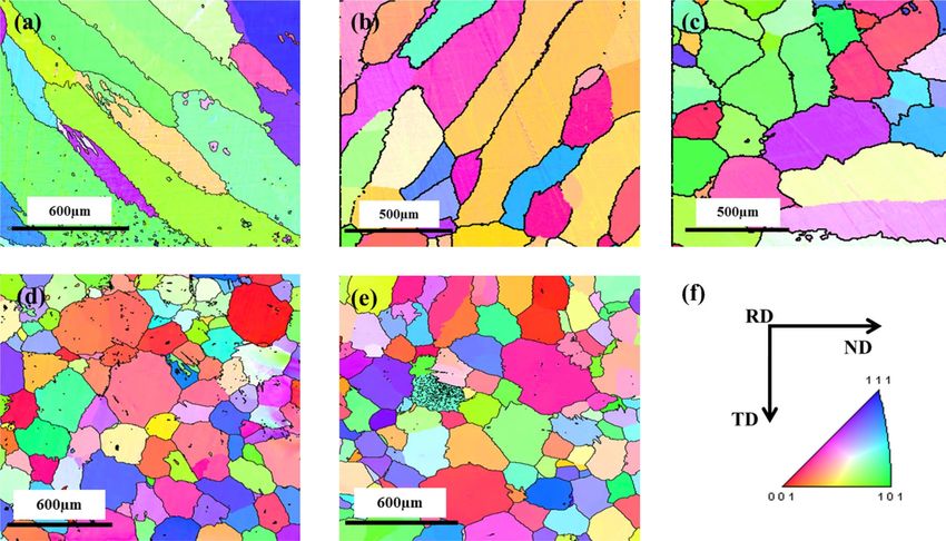
www.nature.com/scientificreports/
to develop during the process of hot rolling of the s teel31–34. Thus, it can be inferred that the entire process of
texture evolution in grain oriented (GO) steels is based upon texture memory and inheritance, apart from the
effect of inhibitors and other topological factors in the primary recrystallized material.
In order to have better control over the texture evolution and to reduce the overall complicacy of the con-
ventional process, strip casting has been extensively explored for grain oriented Si steel. The cast strips are cold
rolled (post optional hot rolling or annealing) followed by primary and secondary a nnealing35–42 to yield sharp
Goss texture. It has been shown that fine recrystallized grains and a strong γ-fiber texture after primary anneal-
ing, yield better strength and sharpness of Goss texture in the thinner sheets of Fe-Si s teels40,41,43. The extensive
research on through process texture evolution has certainly led to the development of optimized process sched-
ules for strip casting based GO steel. However, the quality in terms of magnetic properties (which comes from
the inherent strength and sharpness of Goss texture) of the secondary recrystallized sheet is yet not at par with
the conventionally produced CGO/HGO grades. The primary reason for this is the absence of the hot rolling
step in most of the processing schedule of strip cast products. As already mentioned above, the hot rolling step
plays a crucial role in the inception of Goss grains in the GO s teels31,32,34.
The present investigation is therefore, attempted to combine the advantageous effects of hot rolling with
strip casting by designing a novel thin slab casting route (where the cast thickness is ~ 15 mm). The target was
to enhance the fraction of Goss texture in the hot band; these components not only ensure the presence of the
same as potential nuclei (after primary recrystallization) but also the subsequent cold rolling and annealing
would enhance the requisite (γ- and α-fiber) texture components at the abnormal grain growth step. In order
to enhance the fraction of Goss oriented grains in the hot band, a strategy for enhancing the same in the as cast
product itself was devised. This was attempted with the understanding that, being the stable orientation under
shear deformation during hot rolling, the Goss grains would be inherited from the as cast texture to that of the
hot band. Further, under plane strain compression prevailing at the mid layer of the specimen during hot roll-
ing, the as-cast Goss grains would yield various γ- and α-fiber components which can be retained during cold
rolling; this will create a favourable surrounding for abnormal grain growth.
For obtaining Goss components in the as cast product a novel directional inoculation technique was con-
ceptualized in the present work wherein the advantages of both oriented nucleation as well as oriented growth
would be derived. The oriented nucleation was provided by designed soft magnetic inoculants in the presence
of magnetic field and oriented growth was facilitated by the faster cooling rates during solidification. The com-
parison of through process texture evolution between the directional inoculation based hot band and the thin
slab casting based hot band will be carried out. This will help in understanding the correlation of initial texture
and microstructure of the cast product with the one obtained after hot rolling.
Experimental procedure
Design of directional inoculation technique. The technique of directional inoculation was aimed at
enhancing a particular orientation in the as-cast structure i.e. {110}||ND and ||RD in the present case. For
obtaining a specific texture during diffusional phase transformation (especially in solidification), both oriented
nucleation as well as oriented growth is required. The combination of these two phenomena can lead to a strong
texture in the product phase. This has been achieved in the present work by devising a strategy addressing each
of the two aforementioned aspects independently.
Oriented nucleation aspect. A combination of inoculants and a suitable external stimulus have been employed
to control the initial orientations of the nuclei forming during solidification. Hunter et al.44 have adopted such a
technique for ferritic stainless steels, wherein TiN inoculants are formed in-situ and they lead to oriented nuclea-
tion of the crystals from melt followed by oriented growth owing to the faster cooling rate through the copper
substrate44. Thus, it is clear that the combination of inoculants and an external stimulating field (in the case of
Hunter et al.44, it was density difference) can lead to oriented nucleation during initial stages of solidification.
Inoculation in steels by carbides, nitrides and other mineral particles has been extensively investigated in the
past43,45. However, none of the used inoculants are soft magnetic in nature and therefore, may hamper the final
magnetic properties of the GO steel. It therefore, becomes necessary to design soft magnetic inoculants for the
present work, having good lattice correspondence with the δ-ferrite phase nucleating during solidification. The
above two requirements give way for the choice of Fe based alloys/compounds for the purpose of inoculation
in the present work. The additional advantage of Fe based inoculants is the easy magnetization axis of 46,
which can be aligned along the RD by application of an external magnetic field. However, in order to be effec-
tive for ||RD oriented nucleation, these Fe based inoculants have to be magnetically susceptible at higher
temperatures. It is evident from the literature that amongst the Fe based soft magnetic alloys, Fe–Co systems
tend to possess highest Curie temperatures47. Therefore, based upon the aforementioned requirements of the
inoculants and the inferences drawn from various research works, in the present investigation 65Fe–35Co (wt%)
system was chosen for the purpose of directional inoculation under external magnetic field. The melting point
of this inoculant (~ 1500 °C) lies above that of Fe-Si alloy used in the present investigation (~ 1480 °C). The
solidification of the melt has been carried out in thick copper mould sections which results in faster heat extrac-
tion. With higher cooling rates, the solidification gets initiated at the inoculant surfaces before the temperature
of those inoculants become higher than its Curie point. A cylindrical copper mould, the schematic of which is
given in Fig. 1a, has been prepared with the purpose of providing fast cooling rate to the thin slab ingot cast
within it. The cast ingot typically had a dimension of 180 mm × 65 mm × 15 mm as schematically given in Fig. 1b.
Under axisymmetric considerations, the maximum thickness of the copper mould (and thus the maximum heat
extracting section) for an ingot thickness of 7.5 mm is 59.5 mm (almost 8 times). This thickness of the copper
mould is expected to render rapid extraction of heat in the initial stages of solidification. However, it should be
Scientific Reports | (2021) 11:4912 | https://doi.org/10.1038/s41598-021-84360-0 2
Vol:.(1234567890)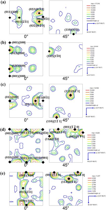
www.nature.com/scientificreports/
Figure 1. Schematic representation of the (a) axisymmetric view of the copper mould; (b) slab ingot cast within
the copper mould; (c) maximum heat extraction direction for different sections of the ingot.
noted here with regards to direction of maximum thickness of the mould (adjacent to ingot), that for all the sec-
tions of the ingot except the centreline, thicker portions of the mould lie at an angle to the ND. This is due to the
cylindrical geometry of the mould and flat geometry of the cavity/ingot. This is schematically shown in Fig. 1c
where the cavity/ingot has been divided into vertical sections and the corresponding maximum heat extraction
direction (depending upon the thickness) for each section has been highlighted.
The magnetic field acting as an external stimulus to orient the inoculants was facilitated by fabricating a
solenoid coil and a DC power supply unit. The mould was placed inside the solenoid coil as a core such that the
solidifying steel ingot lied at the exact center of the solenoid, thereby experiencing a steady state magnetic field
of ~ 20mT (as measured by Gaussmeter) when the current supplied from the source is 200A. The provided
magnetic field although might seem to be very feeble, yet it is good enough to affect and align the inoculant
particles, which has been confirmed by checking its effect on the particles when placed inside the mould cavity.
Oriented growth aspect. From the previous studies on strip cast structure, it is evident that a strong {100}|| ND
(normal direction) texture is attained in the columnar zone. This is attributed to the higher rate of heat extrac-
tion in such solidification process38,39,48–50. The crystallographic planes with highest accommodation factor grow
opposite to the heat extraction direction and outrun other misaligned orientations, thereby attaining a selective
texture component during growth51.
The fast cooling rates provided by the copper mould are expected to lead to a positive temperature gradient
ahead of the solid front and subsequent columnar growth with {100}||ND texture. However, the target texture
component for as cast structure in the present study was {110}||ND and ||RD rather than {100}||ND texture.
The crystals growing with {100}||ND, might not possess ||RD orientation. Therefore, in order to align the
crystals with ||RD, oriented nucleation becomes essential, which has been uniquely devised as mentioned
earlier, in the present work.
Inoculant synthesis. The techniques adopted in the past for the synthesis of Fe–Co alloys vary from
mechanical milling to diode sputtering52–54. However, for the present work a synthesis route is required which
can render higher purity and control over the morphology of the inoculant particles such that size, surface area
and volume of the particles can be optimized. For this purpose a technique of preparing Fe–Co alloys by reduc-
tion of Fe and Co containing salts has been a dopted55. Herein, the sulphate salts of Fe and Co were taken in a
ratio of 2:1 (since the targeted Fe:Co ratio in the alloy is ~ 2:1) and reduced by a solution of sodium hydroxide
(NaOH) and hydrazine ( N2H4) at ~ 90 °C. The reduced product particles were filtered and dried in vacuum fol-
lowed by morphological and structural characterization. The structural characterization was carried out using
Bruker D8 Discover X-Ray Diffractometer having Cu Kα source. The scan was carried out for a 2θ range of
40–120° with an increment of 0.02° and dwell time of two seconds per step. Materials Analysis Using Diffrac-
tion (MAUD) software was used to analyse the XRD pattern for lattice parameter and crystallite size details. The
instrumental Caglioti parameters were determined by performing a scan on standard Si powder and fitting the
Scientific Reports | (2021) 11:4912 | https://doi.org/10.1038/s41598-021-84360-0 3
Vol.:(0123456789)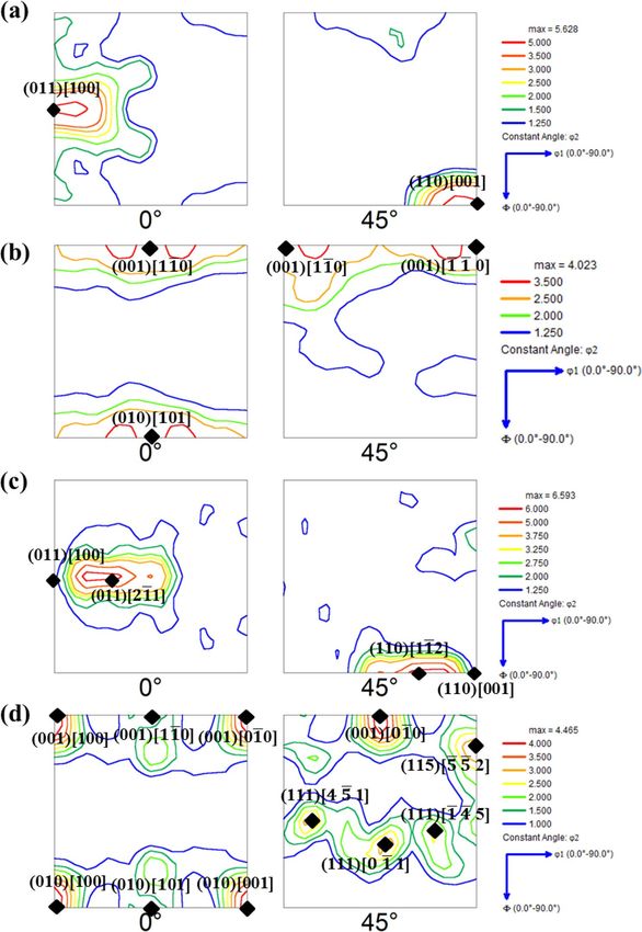
www.nature.com/scientificreports/
Elements C Si Mn S Fe
Content (wt%) 0.04–0.06 3.1–3.2 0.08–0.1 0.008–0.01 Balance
Table 1. Composition range of the cast ingots prepared in the present work.
Casting identification Conditions of casting
Cast 1 Fast Cooling
Cast 2 Fast Cooling + Magnetic Field
Cast 3 Fast Cooling + 0.3 wt% inoculants + Magnetic Field
Cast 4 Fast Cooling + 0.5 wt% inoculants + Magnetic Field
Cast 5 Fast Cooling + 0.8 wt% inoculants + Magnetic Field
Table 2. Casting conditions for various slab ingots.
standard Si pattern with it through MAUD. The instrumental correction for broadening, asymmetry and peak
profile was done using these Caglioti parameters. The morphological and spectroscopic details were character-
ized in FEI Nova Nano FEG SEM attached with an Energy Dispersive X-Ray Spectroscopy detector. For the
purpose of analysing the composition of the particles, the accelerating voltage was maintained in the range of
5–10 kV, so as to minimize the depth of interaction beyond the particle thickness.
Alloy processing. Alloys of composition within the range given in Table 1 were prepared using air induc-
tion furnace and cast in the designed copper mould. The various conditions under which different casting of the
slab ingots were carried out have been listed in Table 2. The first ingot (Cast 1) was cast to assess the effect of fast
cooling rate alone upon the cast structure and texture, whereas the second ingot (Cast 2) was cast in the same
copper mould along with the presence of external magnetic field. Three more ingots (Cast 3–5) were cast in the
copper mould along with addition of 0.3, 0.5 and 0.8 wt% (of the ingot) of Fe–Co inoculants. These castings were
done in the presence of external magnetic field as well so as to have the effect of directional inoculation during
solidification in these ingots. The inoculants were wrapped in laboratory grade aluminium foils and half of it
was placed in the mould prior to pouring of the liquid metal and rest half was added during the time of pouring.
It was expected that the particles would be circulated throughout the cavity owing to the liquid metal thermo-
solutal convection during pouring. Further specimens of dimension 80 mm × 40 mm × 15 mm were taken from
the ingot and subjected to reheating at 1200 °C for 3 h followed by single stage hot rolling in laboratory scale
two high hot rolling mill to a final thickness of ~ 2 mm. The reason for selection of 1200 °C as the reheating
temperature has been given elsewhere56. The design of the hot rolling schedule was also based upon the infer-
ences drawn from the previous works regarding the effect of draft schedules on the microstructural, textural and
magnetic properties57–59. The hot rolling schedule consisted of 3 passes: the first pass consisted of a reduction
level of ~ 60% so as to yield dynamically recrystallized grains and fine distribution of precipitates (MnS) dur-
ing the subsequent interpass time. The second pass consisted of a moderate reduction level of ~ 40% with the
aim of attaining dynamic and static (in the subsequent interpass time) recrystallization at the surface whereas
recovered/static recrystallized grains at the center. The third pass of ~ 45% was given with the aim of producing
dynamically recrystallized grains again at the surface while recovered grains are obtained at the center. After the
hot rolling, the hot band was air cooled to room temperature.
Microtexture characterization. The microtexture characterization of both as cast and hot rolled prod-
ucts were carried out in the FEI Nova Nano FEG SEM equipped with TSL DigiView III EBSD detector. For
acquiring the texture of the as cast structure, a minimum of 1.5 mm × 1.5 mm area in the ND-TD section at the
center of the ingot was scanned whereas for the hot band specimens, through thickness areas in the ND-RD
section were scanned. The samples for microtexture were prepared by standard metallographic techniques. The
data acquisition was carried out at an accelerating voltage of 20 kV with a total specimen tilt of 72°. The analysis
of the acquired microtexture data was carried out using TSL OIM 7.0 software. The microtexture is represented
in the present work by Inverse Pole Figure (IPF) maps depicting the crystallographic plane perpendicular to ND
The ODFs are sections of the Euler space represented by ϕ1, ϕ and ϕ2 axes, of which the constant ϕ2 sections of
and Orientation Distribution Functions (ODF) computed by the series expansion (rank = 22) (Bunge) method.
0° and 45° are used for the present work.
Results and discussion
Fe–Co inoculants. The XRD pattern of Fe–Co particles is given in Fig. 2a. It also shows the standard pow-
der diffraction pattern of Fe–Co system (with Space Group Pm 3 m) fitted to the experimental pattern using
MAUD software along with the residual of the fitting. The standard pattern of a primitive cubic crystal system is
selected because the Fe–Co particles synthesized in the present work are expected to be an ordered phase having
a primitive structure owing to the composition and temperature of synthesis47. The lattice parameter of the syn-
thesized Fe–Co alloy was determined to be ~ 2.87 Å. The approximate lattice parameter of Fe-Si system in BCC
Scientific Reports | (2021) 11:4912 | https://doi.org/10.1038/s41598-021-84360-0 4
Vol:.(1234567890)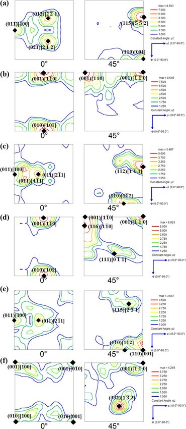
www.nature.com/scientificreports/
Figure 2. (a) XRD pattern of the Fe–Co alloy synthesized in the present work (peak profile fitting carried out
using MAUD); (b) SEM micrograph of the Fe–Co particles and (c) composition of the particles as acquired by
EDS.
structure is 2.86 Å. Thus, it can be inferred that in terms of lattice registry, the inoculants must be effective. The
crystallite size of the particles determined from XRD is ~ 0.30 µm. The SEM micrograph given in Fig. 2b shows
the faceted cubic morphology of the particles with an average particle size of ~ 0.30 µm. This indicates that the
particles are single crystals and thus the faces of the cubic morphology can be inferred as {100} crystallographic
planes of the Fe–Co cubic crystal.
Further, this leads to the inference that these {100} crystallographic planes of the inoculant exposed at the
particle surface would act as a substrate for the nucleation of {100} planes of the solidifying crystals on it. The
composition of the Fe–Co powder synthesized in the present work and as measured using EDS has been given
in Fig. 2c, which confirms the formation of ~ 68 wt% Fe–32 wt% Co alloy.
Microstructure and microtexture of the slab cast ingots. The IPF maps of the ND-TD section for
Cast 1–5 are given in Fig. 3a–e, respectively. Figure 3f shows the directions of the slab ingot with respect to the
scanned sections. The texture represented in the present work is in terms of {hkl} , where ||ND
and || RD.
It can be observed from Fig. 3a, b that the cast structure is dominated by coarse columnar grains in the
absence of any inoculants, whereas Fig. 3c–e depict refined equiaxed grains with the addition of inoculants. The
inoculants were thus, found to be effective in its role of refining the microstructure, as observed from the IPF
maps. The IPF maps of Fig. 3a, b also depict that the columnar grains are aligned at an angle to the ND (close to
45°). These long columnar grains aligned at an angle to the ND confirm the expected difference in the maximum
heat extraction direction along the TD of the ingot as mentioned in “Oriented nucleation aspect” section and
Fig. 1c. The direction of heat extraction is thus inferred to depend upon the direction of maximum thickness of
the mould adjacent to the ingot.
Before proceeding on to the analysis of as cast microtexture, the standard ODF sections of φ2 = 0° and 45°
of the Euler space along with some common orientations and fibers that occur in BCC alloys are presented in
Fig. 4a, b, respectively33,60.
Figure 5a–e represent the ODF sections of φ2 = 0° and 45° for the Cast 1–5 ingots, respectively. The major ori-
entations observed in these ODFs have been marked as well in Fig. 5a–e. As can be seen from Fig. 5a, the as cast
structure of Cast 1 consists of columnar grains with crystallographic planes close to {011} parallel to the rolling
Scientific Reports | (2021) 11:4912 | https://doi.org/10.1038/s41598-021-84360-0 5
Vol.:(0123456789)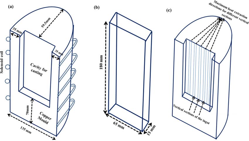
www.nature.com/scientificreports/

                                            Figure 3.  IPF maps of (a) Cast 1, (b) Cast 2, (c) Cast 3, (d) Cast 4, (e) Cast 5 and (f) directions of the slab ingot
                                            with respect to the scanned surface.

                                            Figure 4.  (a) φ2 = 0° section and (b) φ2 = 45° section of the Euler space along with some common orientations
                                            and fibers that occur in BCC metals and alloys.

                                            plane (i.e. perpendicular to ND). This observation is in concurrence with the observation of tilted columnar
                                            grains in the IPF given in Fig. 3a. As already discussed, the alignment of the columnar grains is such that they
                                            grow opposite to the maximum heat extraction direction. In the process of this growth, the {001} planes being
                                            the most loosely packed ones (and with the highest accommodation factor) tend to align perpendicular to the
                                            growth direction. Since the maximum heat extraction direction is at an angle to the ND (as shown in Fig. 1c),
                                            the {001} planes tend to maintain an angle with the ND and this ultimately leads to development of orienta-
                                            tions close to {011} being perpendicular to ND. The major orientations observed are close to Brass component
                                            ({011}) and P orientation (Fig. 5a).
                                                In case of Cast 2 ingot, near cube type orientation of the columnar grains is observed. This might have hap-
                                            pened due to the effect of magnetic field upon the solidification process. However, it is essential to realize that
                                            the solidifying crystals of Fe-Si alloy would start experiencing magnetic field only below the Curie temperature
                                            of steel (~ 750 °C) where it is ferromagnetic. Therefore, the effect of magnetic field upon the orientation of the

          Scientific Reports |   (2021) 11:4912 |                https://doi.org/10.1038/s41598-021-84360-0                                                      6

Vol:.(1234567890)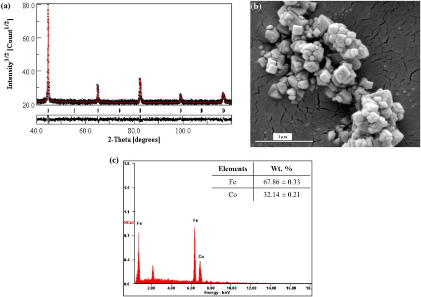
www.nature.com/scientificreports/

                                  Figure 5.  φ2 = 0° and 45° sections of the ODF for (a) Cast 1; (b) Cast 2; (c) Cast 3; (d) Cast 4 and (e) Cast 5.

                                  crystals can only be expected when the cast ingot lies in a two phase semi solid zone consisting of solid crystals
                                  below Curie temperature (near the mould wall) and surrounding liquid melt (towards center). Under these

Scientific Reports |   (2021) 11:4912 |                https://doi.org/10.1038/s41598-021-84360-0                                                     7

                                                                                                                                                 Vol.:(0123456789)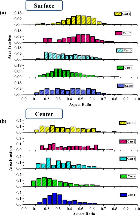
www.nature.com/scientificreports/
Figure 6. IPF maps of hot bands prepared from (a) Cast 1, (b) Cast 2, (c) Cast 3, (d) Cast 4, (e) Cast 5 and (f)
directions of the hot rolled strip with respect to the scanned surface.
conditions, the solidified crystals near the mould wall (chilled zone) would tend to have one of the easy mag-
netization axes ([100]) parallel to the applied field.
Moreover, because of a drastic temperature drop just adjacent to the mould wall, these grains may have one
of the loosely packed cube faces, (001) perpendicular to ND.
From these cube on face-oriented crystals, columnar grains opposite to maximum heat extraction directions
would grow. This would lead to orientations with [100] || RD, but with crystallographic planes between (001)
and (011) perpendicular to ND, as observed in 0° section of Fig. 1b.
In case of Cast 3 ingot, the equiaxed grains (as compared to Cast 1 and Cast 2) with orientations between
Goss (i.e. {011}) and Rotated Goss (i.e. {011}) are observed. This indicates that despite of the addi-
tion of heterogeneous sites of nucleation to the melt, the as cast structure contains fairly strong texture, which
is also supported by the IPF maps (Fig. 3c) and the maximum level of intensity in ODF given in Fig. 5c. The as
cast orientations of the ξ fiber (ranging from [100] to [011] parallel to RD) observed in case of Cast 3, indicate
that Fe–Co particles by virtue of alignment of the easy magnetization axis along the applied magnetic field
have indeed initiated a directional inoculation of the steel melt with cube on face orientations. These nucleated
crystals further grew under the effect of fast cooling leading to {011} planes perpendicular to ND. However,
these heterogeneously nucleated grains are expected to experience thermo-solutal convection of liquid leading
to deviation from ideal || RD orientations; thus, giving way to near Rotated Goss components. Thus the
major observed orientations in Cast 3 ingot are splitted Goss component {011} and P orientation (Fig. 5c).
In case of Cast 4 and 5 ingots, the ODF sections depict randomization of texture due to higher fraction of
inoculants (Fig. 5d, e). The grain size in these ingots was also observed to be finer (Fig. 3d, e) as compared to
Cast 3, which can again be attributed to addition of higher inoculant fraction. It is worth noting that even though
texture randomization has taken place, in case of Cast 4, the orientations are still centred about || ND fiber
(refer Fig. 4a). This indicates the increasing effect of oriented nucleation by directional inoculation over oriented
growth by faster cooling rates. The deviation of axes from being parallel to the RD (as would be in case of
cube on face orientation) can be attributed to the melt convection either during pouring or due to thermo-solutal
gradients. The prominent orientations in both the cases lie within the Cube-Rotated Cube fiber (Fig. 5d, e).
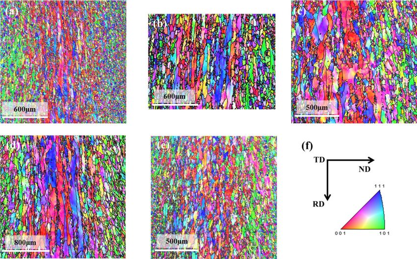
Microstructure and microtexture of the hot bands. The IPF maps acquired on the through thickness
ND-RD sections of the hot bands produced from Cast 1–5 ingots are shown in Fig. 6a–e respectively. Figure 6f
shows the directions of the hot band with respect to the scanned sections. These IPF maps clearly depict the
microstructural and textural gradient which is desirable for the subsequent processing of GO s teel32,34,57,61. This
microstructural gradient consists of recrystallized fine grains at the surface and recovered elongated grains at
the center of the strip.
Scientific Reports | (2021) 11:4912 | https://doi.org/10.1038/s41598-021-84360-0 8
Vol:.(1234567890)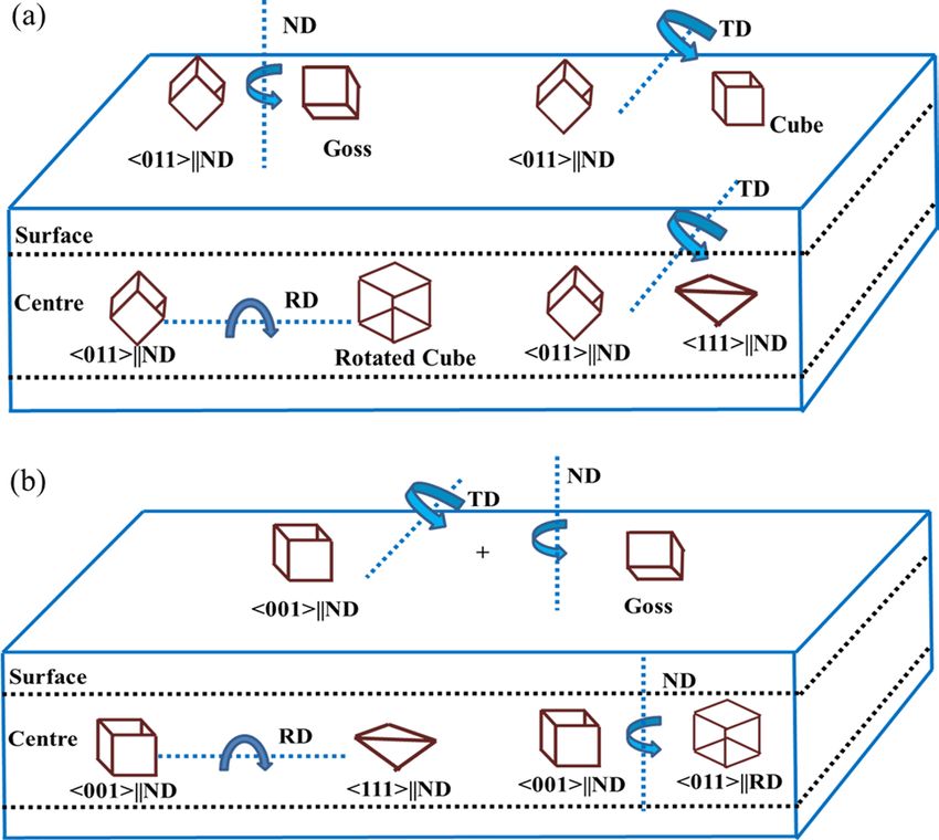
www.nature.com/scientificreports/

                                  Figure 7.  φ2 = 0° and 45° sections of hot bands from (a) left surface of Cast 1; (b) center of Cast 1; (c) right
                                  surface of Cast 2; (d) center of Cast 2.

                                      The microstructural gradients although have a similar trend in all the hot rolled strips, yet there were mor-
                                  phological differences between them. Since, neither the alloy composition nor the hot rolling schedule was
                                  significantly different in these 5 cases; the differences in the morphology could be attributed to difference in the
                                  initial orientations prior to rolling and the subsequent recrystallization kinetics. Therefore, it becomes essential
                                  to assess the morphological differences between the different microstructural features of the hot bands in con-
                                  junction with the respective microtexture details.
                                      For this correlation, the ODFs of the surface and center portions of each hot band have been evaluated sepa-
                                  rately and compared across all the hot bands. The φ2 = 0° and 45° sections of ODFs from one of the surfaces and
                                  center of the hot bands from Cast 1 and 2 are given in Fig. 7a–d. Similarly, the φ2 = 0° and 45° sections of ODFs
                                  from one of the surfaces and center of hot bands from Cast 3, 4 and 5 are given in Fig. 8a–f. The major orienta-
                                  tions observed in these ODFs of the hot bands (as marked in the respective figures) and their corresponding

Scientific Reports |   (2021) 11:4912 |                https://doi.org/10.1038/s41598-021-84360-0                                                      9

                                                                                                                                                  Vol.:(0123456789)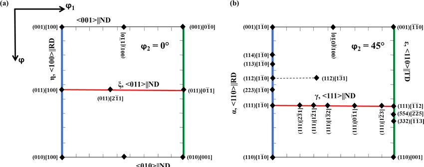
www.nature.com/scientificreports/
Figure 8. φ2 = 0° and 45° ODF sections of hot bands from (a) right surface of Cast 3; (b) center of Cast 3; (c)
surface of Cast 4; (d) center of Cast 4; (e) surface of Cast 5 and (f) center of Cast 5.
initial orientations observed in the as cast structure (Fig. 5) are also laid out in Table 3. Before proceeding to the
microtexture analysis of the hot rolled strips, it is worth noting that during hot rolling, the surface of the strips
experiences extensive shear deformation whereas the center experiences conditions similar to that of plane strain
compression32,33. Under shear deformation, the grains are expected to rotate about TD and ND or any other
axis in between these two, such that the close packed planes (i.e. {011}) become parallel to the rolling plane. In
case of PSC, the predominant rotations are about RD and ND. Moreover, deformation has also been shown to
be accommodated by rotation taking place within small ‘in band crystal volumes’ about crystallographic axes
aligned along TD31,62. These rotations are manifested in the microstructure in the form of various fiber texture
components; the prominent ones of which are γ fiber (||ND), α fiber (||RD), ξ fiber (||ND)
Scientific Reports | (2021) 11:4912 | https://doi.org/10.1038/s41598-021-84360-0 10
Vol:.(1234567890)www.nature.com/scientificreports/
Major texture components
Material As cast Hot band surface Hot band center
Near Brass ({011}) and near Rotated Goss com-
Cast 1 Goss orientation ({011}) Rotated cube orientation ({001})
ponent ({011})
Cast 2 Near Cube orientation ({001}) Near Brass ({011}) orientation γ fiber components
Near Goss ({011}) and near Rotated Goss com- Goss orientation ({011}) and {4 4 11} orientation
Near cube ({001}) and rotated cube orientations Near Goss orientation ({011}) and near Brass
Cast 4 γ and α fiber components
({001}) ({011}) orientation
Near Goss orientation ({011}) and near Brass γ fiber components and Near cube and rotated cube
Cast 5 Rotated cube orientations ({001})
({011}) orientation orientations
Table 3. Major texture components observed in the as cast and corresponding hot band microstructures.
and ||ND fiber, etc. The position of these fiber texture components along φ–φ1 at constant φ2 sections of
ODF have been indicated in Fig. 4a, b as well.
It can be seen from Figs. 7a, b and 8a, b, the major texture components in the hot band produced from Cast 1
and 3 are quite similar. The orientations in the surface layers of these hot bands are centred strongly about Goss
and other ξ fiber components except for the additional presence of near {4 4 11} orientations in Cast 3
hot band (Fig. 8a, b). The center of the hot bands from these ingots possess strong ||ND fiber texture along
with meagre γ fiber components in Cast 1 hot band (Fig. 7a, b).
In the case of surface of the hot band prepared from Cast 1 and Cast 3 ingots, the initial orientation of {011}
planes parallel to the rolling plane, leads to rotation about ND and subsequent Goss texture formation (by
repeated recrystallization and deformation)33 as observed in Figs. 7a and 8a. These initially {011} parallel to roll-
ing plane oriented grains would recrystallize at relatively later stages as compared to what was expected during the
design of the hot rolling schedule (mentioned in “Alloy processing” section). This is due to reduced dislocation
activity on these crystallographic orientations31,62. Therefore, at the end of the first pass, the surface grains would
statically recrystallize during the interpass time, which would further get deformed and partially recrystallized
before the last deformation. In the third pass, the surface grains under the effect of previous unrecrystallized state
and increased draft undergo dynamic recrystallization leading to formation of very fine recrystallized grains, as
observed in Fig. 6a. Despite of the similarity in the initial texture components and hot rolling parameters (and
hence, similar aforementioned sequence of deformation and recrystallization), difference in the morphology
and grain size of hot bands was observed. The difference in the morphology of grains at hot band surface is
more evident from the grain shape aspect ratio charts given in Fig. 9a. The grain shape aspect ratio is measured
by fitting an elliptical shape in the grains of the structure and evaluating the ratio of minor to major axis of the
ellipse. The maps given in Fig. 9a, b basically depict the grain shape aspect ratio distribution of the surface (the
corresponding ODFs of which are given in Figs. 7 and 8) and center of all the hot bands. Figure 9a clearly shows
that the aspect ratio of surface grains in Cast 3 hot band is significantly lesser than the Cast 1 hot band, depict-
ing presence of pancaked grains in the former. With similar initial orientations, such contrasting features can
be attributed to the difference in the as cast grain size and morphology between the Cast 1 (coarse columnar)
and Cast 3 (fine equiaxed) ingots. In case of Cast 1, the first recrystallization would be delayed to later duration
of interpass holding (post first pass) due to the coarse microstructure, thereby leading to finer grains before the
second pass as compared to Cast 3 48. These would lead to even finer equiaxed grains in the surface of hot band
produced from Cast 1 as compared to that of Cast 3 (refer Fig. 6a, c). The aspect ratio distribution of Cast 1 and
3 hot bands given in Fig. 9a confirms the hypothesized sequence of deformation and recrystallization as well.
In the central layers of the hot band prepared from Cast 1 ingot, the near Goss oriented grains present in the
as cast structure rotate to γ fiber components which are the stable end orientations under PSC condition29,31,33 as
observed in the φ2 = 45° sections of Fig. 7b. Moreover, the initial near rotated Goss orientations present in Cast
1 and Cast 3 ingots, under PSC would develop near cube orientations in localized crystal volumes which evolve
as recrystallized cube oriented grains as w ell62. These can further lead to both γ fiber components and rotated
cube orientations as prominently observed in Figs. 7b and 8b respectively. As already discussed, the difference
in the initial grain size of Cast 1 and Cast 3 leads to the delayed recrystallization of the central layers in case of
hot band of Cast1 as compared to that of Cast 3. This, further under deformation in subsequent pass leads to
grains with lower aspect ratio (in the range of 0–0.2) to be more prominently present in the central layers of Cast
1 (Figs. 6a and 9b) as compared to that of Cast 3 (Figs. 6c and 9b).
Similarity in the hot band texture can also be observed amongst Cast 2, 4 and 5. The surface layers of the hot
bands from these ingots exhibit strong Goss and ξ fiber components, as can be seen from Figs. 7c and 8c, e. In
contrast to the surface, the center portions of the hot bands from these ingots possess strong γ and α fiber texture.
In case of Cast 2, 4 and 5, the initially near cube oriented grains would rotate about TD and ND (or any other
direction in between) leading to strong near Goss texture or other ξ fiber components in the surface layers as
observed in φ2 = 0° sections of Figs. 7c, and 8c, e, respectively. The presence of these ξ fiber components confirm
that the initial rotation takes place about TD or other directions close to TD so that the cube orientations attain
{011} plane parallel to RD. The subsequent rotations take place about ND as these ξ fiber components consist
of stable end orientations under shear deformation. The rotation about TD is also confirmed from the presence
of orientations near another shear induced component, {4 4 11} , as observed in the φ2 = 45° section
of Figs. 7c, and 8c, e.
Scientific Reports | (2021) 11:4912 | https://doi.org/10.1038/s41598-021-84360-0 11
Vol.:(0123456789)www.nature.com/scientificreports/
Figure 9. Grain shape aspect ratio distribution in the (a) surface layers and (b) central layers of all the hot
bands produced from different ingots.
The strong γ and α fiber components in the central layers of the hot bands from Cast 2, 4 and 5 owe their
origin to the initial near cube orientations, which under PSC would easily rotate about ND to yield stable rotated
cube components and about RD to γ fiber c omponents42. The γ fiber texture, although is observed to be stronger
in case of Cast 2 hot band (Fig. 7d) as compared to Cast 4 or 5 (Fig. 8d, f), yet the morphological gradient for
further processing seems to be more suitable in case of Cast 4 and 5 hot bands (Fig. 6c, d). This is also clearly
evident from the grain shape aspect ratio distribution given in Fig. 9b where the central layers of Cast 2 hot band
are shown to possess high aspect ratio grains in contrary to Cast 4 and 5 hot bands. The underlying reason for this
difference in morphological gradient is the combination of starting texture component and grain size, which in
case of Cast 2 are near cube and coarse columnar respectively. These coarse columnar near cube oriented grains
can easily rotate about ND to stable end rotated cube components which have highly sluggish recrystallization
kinetics63. This leads to delayed recrystallization in the later stages of interpass holding post first pass of hot
rolling, static recovery post the second pass followed by partial dynamic recrystallization in the final pass (refer
Fig. 6b). On the contrary, due to the fine equiaxed grains present in the as cast structure of Cast 4 and 5, the
recrystallization takes place at an earlier stage followed by growth, post the first pass of hot rolling. These would
undergo dynamic and static recovery post the second and third pass, ultimately leading to recovered grain in
the center as observed in Fig. 6d, e.
Thus, the hot bands from Cast 4 and 5 consist of fine Goss to Brass ({011}) oriented grains in the surface
and elongated recovered γ and α fiber components, which is most suitable for further processing of GO steels.
The major texture components of the hot band and the corresponding plausible evolution from the initial
orientations of each ingot are shown schematically in Fig. 10a for Cast 1, Cast 3 and Fig. 10b for Cast 2, 4 and 5.
Conclusion
In the present work, a novel technique of directional inoculation has been devised and applied for production
of hot bands with microstructural and textural gradient suitable for GO steel production. The target was to cast
ingots under the effect of directional inoculation so as to begin with an as cast thin slab containing Goss oriented
components. The target was set so, because the Goss components are expected to provide potential nuclei (Goss
grains) as well as suitable surrounding texture (γ and α fiber components) for abnormal grain growth. The design
Scientific Reports | (2021) 11:4912 | https://doi.org/10.1038/s41598-021-84360-0 12
Vol:.(1234567890)www.nature.com/scientificreports/
Figure 10. Schematic representation of the major texture components of the hot band and the corresponding
plausible evolution from the initial orientations for (a) Cast 1 and 3; (b) Cast 2, 4 and 5.
of the directional inoculation technique relied upon the use of soft magnetic inoculants for providing oriented
nucleation under the effect of external magnetic field, as well as upon the fast cooling rates for providing ori-
ented growth. Ingots were cast under different conditions and the solidification texture was analysed in light of
the effect of various involved parameters. It was observed that the directional inoculation technique was indeed
capable of inducing near Goss oriented components in the as cast structure when the inoculants were added
at an optimal amount. Higher addition of inoculants led to finer equiaxed grains in the as cast structure with
cubic orientations. The hot rolling of these ingots was carried out and it was observed that the ingots with cube
texture components and fine grains evolved into the most suitable hot band microstructure with the requisite
microstructural and microtextural gradient. The developed hot band textures in case of each ingot was analysed
in terms of different plausible rotations of crystal during deformation. It was observed that during hot rolling, the
most predominant rotations for the surface of hot band take place about the ND and TD (or any other direction
in between). On the contrary, for the central layers, the most prominent rotations are about all the three ND,
RD and TD, depending upon the initial orientation.
Received: 23 October 2020; Accepted: 15 February 2021
References
1. Günther, K., Abbruzzese, G., Fortunati, S. & Ligi, G. Recent technology developments in the production of grain-oriented electrical
steel. Steel Res. Int. 76, 413–421. https://doi.org/10.1002/srin.200506030 (2005).
2. Matsuo, M. Texture control in the production of grain oriented silicon steels grain oriented. ISIJ Int. 29, 809–827 (1989).
3. Littmann, M. F. Grain-oriented silicon steel sheets. J. Magn. Magn. Mater. 26, 1–10 (1982).
4. Kubota, T., Mizokami, M., Fujikura, M. & Ushigami, Y. Electrical steel sheet for eco-design of electrical equipment (2000).
5. Zaefferer, S. & Chen, N. The Goss texture formation in silicon steels—growth selection or oriented nucleation?. Solid State Phenom.
105, 29–36. https://doi.org/10.4028/www.scientific.net/ssp.105.29 (2005).
6. Chen, N., Zaefferer, S., Lahn, L., Günther, K. & Raabe, D. Effects of topology on abnormal grain growth in silicon steel. Acta Mater.
51, 1755–1765. https://doi.org/10.1016/S1359-6454(02)00574-8 (2003).
7. Bréchet, Y. & Militzer, M. A note on grain size dependent pinning. Scr. Mater. 52, 1299–1303. https://doi.org/10.1016/j.scriptamat
.2005.02.021 (2005).
8. Guo, W. & Mao, W. Abnormal growth of Goss grains in grain-oriented electrical steels. J. Mater. Sci. Technol. 26, 759–762. https
://doi.org/10.1016/S1005-0302(10)60120-X (2010).
9. Guo, W., Mao, W., Li, Y. & An, Z. G. Influence of intermediate annealing on final Goss texture formation in low temperature
reheated Fe-3%Si steel. Mater. Sci. Eng. A 528, 931–934 (2011).
10. Gao, Y., Xu, G., Guo, X., Li, G. & Wang, Y. Primary recrystallization characteristics and magnetic properties improvement of high
permeability grain-oriented silicon steel by trace Cr addition. J. Magn. Magn. Mater. https://doi.org/10.1016/j.jmmm.2020.16684
9 (2020).
11. Bernier, N., Xhoffer, C., Van De Putte, T., Galceran, M. & Godet, S. Structure analysis of aluminium silicon manganese nitride
precipitates formed in grain-oriented electrical steels. Mater. Charact. 86, 116–126. https://doi.org/10.1016/j.matchar.2013.09.014
(2013).
12. Stoyka, V., Kováč, F., Stupakov, O. & Petryshynets, I. Texture evolution in Fe-3% Si steel treated under unconventional annealing
conditions. Mater. Charact. 61, 1066–1073. https://doi.org/10.1016/j.matchar.2010.06.020 (2010).
13. Gao, Y., Xu, G., Guo, X. & Li, G. Effect of Cr on secondary recrystallization behaviors in high permeability grain oriented
silicon steel manufactured by low-temperature slab reheating. J. Magn. Magn. Mater. 476, 428–436. https://doi.org/10.1016/j.
jmmm.2018.12.067 (2019).
14. Omura, T. & Hayakawa, Y. Influence of primary-recrystallization texture on selective growth of goss grains. Mater. Trans. 54,
14–21. https://doi.org/10.2320/matertrans.M2012303 (2013).
Scientific Reports | (2021) 11:4912 | https://doi.org/10.1038/s41598-021-84360-0 13
Vol.:(0123456789)www.nature.com/scientificreports/
15. Shimizu, R. & Harase, J. Coincidence grain boundary and texture evolution in Fe-3 % Si. Acta Met. 37, 1241–1249 (1989).
16. Harase, J., Shimizu, R. & Dingley, D. J. Texture evolution in the presence of precipitates in Fe-3%Si alloy. Acta Met. Mater. 39,
763–770 (1991).
17. Harase, J. & Shimizu, R. Texture evolution by grain growth in the presence of MnS and AlN precipitates in Fe-3% Si alloy. Acta
Met. Mater. 38, 1395–1403 (1990).
18. Lin, P., Palumbo, G., Harase, J. & Aust, K. T. Coincidence site lattice grain boundaries and Goss texture development in Fe-3% Si
alloy. Acta Mater. 44, 4677–4683 (1996).
19. Hayakawa, Y. & Szpunar, J. A. A new model of Goss texture development during secondary recrystallization of electrical steel.
Acta Mater. 45, 4713–4720 (1997).
20. Rajmohan, N., Szpunar, J. A. & Hayakawa, Y. A role of fractions of mobile grain boundaries in secondary recrystallization of Fe-Si
steels. Acta Mater. 47, 2999–3008 (1999).
21. Park, H. K., Han, C. H., Park, C. S., Park, J. T. & Joo, H. D. Abnormal grain growth induced by grain boundary segregation of
yttrium in grain-oriented Fe-3%Si steel. Mater. Charact. 146, 204–208. https://doi.org/10.1016/j.matchar.2018.09.047 (2018).
22. Ushigami, Y., Kubota, T. & Takahashi, N. Mechanism of orientation selectivity of secondary recrystallization in Fe-3%Si alloy. ISIJ
Int. 38, 553–558 (1998).
23. Kumano, T., Haratani, T. & Ushigami, Y. Influence of primary recrystallization texture through thickness to secondary texture on
grain oriented silicon steel. ISIJ Int. 43, 400–409 (2003).
24. Song, H. Y., Liu, H. T., Jonas, J. J. & Wang, G. D. Effect of primary recrystallization microstructure on abnormal growth of Goss
grains in a twin-roll cast grain-oriented electrical steel. Mater. Des. 131, 167–176. https://doi.org/10.1016/j.matdes.2017.06.016
(2017).
25. Lee, S., Ko, K. J., Kim, S. J. & Park, J. T. Statistical analysis of EBSD data to predict potential abnormal grain growth in 3.0 wt% Si
grain-oriented electrical steel. Mater. Charact. https://doi.org/10.1016/j.matchar.2020.110450 (2020).
26. Liu, Y. et al. Goss texture evolution of grain oriented silicon steel by high-energy X-ray diffraction. Acta Metall. Sin. Engl. Lett. 27,
530–533. https://doi.org/10.1007/s40195-014-0082-y (2014).
27. Chang, S. K. & Hong, B. D. Secondary recrystallization behavior in 3% Si grain oriented steels. ISIJ Int. 44, 1086–1092 (2004).
28. Dunn, C. G. Cold-rolled and primary recystallization textures in cold-rolled single crystals of silicon iron. Acta Metall. 2, 173–183
(1954).
29. Dorner, D., Lahn, L. & Zaefferer, S. Survival of Goss grains during cold rolling of a silicon steel single crystal. Mater. Sci. Forum.
495–497, 1061–1066. https://doi.org/10.4028/www.scientific.net/msf.495-497.1061 (2005).
30. Hu, H. A study on the texture formation in rolled and annealed crystals of silicon-iron. Trans. TMS Am. Inst. Min. Eng. 221,
130–140 (1961).
31. Dorner, D., Zaefferer, S. & Raabe, D. Retention of the Goss orientation between microbands during cold rolling of an Fe3%Si single
crystal. Acta Mater. 55, 2519–2530. https://doi.org/10.1016/j.actamat.2006.11.048 (2007).
32. Mishra, S., Darmann, C. & Lucke, K. On the development of the goss texture in iron-3% silicon. Acta Met. 32, 2185–2201 (1984).
33. Mishra, S., Darmann, C. & Lucke, K. New information on texture development in regular and high-permeability grain-oriented
silicon steels. Metall. Trans. A 17, 1301–1312 (1986).
34. Shimizu, Y., Ito, Y. & Iida, Y. Formation of the goss orientation near the surface of 3 pct silicon steel during hot rolling. Metall.
Trans. A 17A, 1323–1334 (1986).
35. Park, J. Y., Oh, K. H. & Ra, H. Y. The effects of superheating on texture and microstructure of Fe–4.5wt%Si steel strip by twin-roll
strip casting. ISIJ Int. 41, 70–75 (2001).
36. Song, H. Y. et al. Microstructure and texture of strip cast grain-oriented silicon steel after symmetrical and asymmetrical hot roll-
ing. Steel Res. Int. 85, 1477–1482. https://doi.org/10.1002/srin.201300385 (2014).
37. Song, H. Y. et al. Effect of hot rolling reduction on microstructure, texture and ductility of strip-cast grain-oriented silicon steel
with different solidification structures. Mater. Sci. Eng. A 605, 260–269. https://doi.org/10.1016/j.msea.2014.03.052 (2014).
38. Liu, H. T. et al. Evolution of microstructure, texture and inhibitor along the processing route for grain-oriented electrical steels
using strip casting. Mater. Charact. 106, 273–282. https://doi.org/10.1016/j.matchar.2015.06.010 (2015).
39. Wang, Y. et al. Effect of annealing after strip casting on texture development in grain oriented silicon steel produced by twin roll
casting. Mater. Charact. 107, 79–84. https://doi.org/10.1016/j.matchar.2015.07.001 (2015).
40. Lu, X. et al. Secondary recrystallization behavior in strip-cast grain-oriented silicon steel processed by isothermal secondary
annealing. Mater. Charact. 142, 68–76. https://doi.org/10.1016/j.matchar.2018.05.029 (2018).
41. Song, H. Y. et al. Fabrication of grain-oriented silicon steel by a novel way: strip casting process. Mater. Lett. 137, 475–478. https
://doi.org/10.1016/j.matlet.2014.09.075 (2014).
42. Liu, H. T., Liu, Z. Y., Sun, Y., Gao, F. & Wang, G. D. Development of λ-fiber recrystallization texture and magnetic property in
Fe-6.5 wt% Si thin sheet produced by strip casting and warm rolling method. Mater. Lett. 91, 150–153. https://doi.org/10.1016/j.
matlet.2012.09.046 (2013).
43. Gregg, J. M. & Bhadeshia, H. K. D. H. Solid-state nucleation of acicular ferrite on minerals added to molten steel. Acta Mater. 45,
739–748 (1997).
44. Hunter, A. & Ferry, M. Texture enhancement by inoculation during casting of ferritic stainless steel strip. Metall. Mater. Trans. A
33A, 1499–1507 (2002).
45. Villafuerte, J. C., Pardo, E. & Kerr, H. W. The effect of alloy composition and welding conditions on columnar-equiaxed transitions
in ferritic stainless steel gas-tungsten arc welds. Metall. Trans. A 21A, 2009–2019 (1990).
46. Turgut, Z., Nuhfer, N. T., Piehler, H. R. & McHenry, M. E. Magnetic properties and microstructural observations of oxide coated
FeCo nanocrystals before and after compaction. J. Appl. Phys. 85, 4406–4408. https://doi.org/10.1063/1.369799 (1999).
47. Sourmail, T. NearequiatomicFeCo alloys: constitution, mechanical and magnetic properties. Prog. Mater. Sci. 50, 816–880. https
://doi.org/10.1016/j.pmatsci.2005.04.001 (2005).
48. Lu, X. et al. Evolution of microstructure and texture in grain-oriented 6.5%Si steel processed by strip-casting. Mater. Charact. 126,
125–134. https://doi.org/10.1016/j.matchar.2017.02.022 (2017).
49. Strezov, L. & Herbertson, J. Experimental studies of interfacial heat transfer and initial solidification pertinent to strip casting. ISIJ
Int. 38, 959–966 (1998).
50. Hunter, A. & Ferry, M. Evolution of microstructure and texture during casting of AlSi 304 stainless steel strip. Metall. Mater. Trans.
A 33A, 3747–3754 (2002).
51. Chalmers, B. Principles of Solidification (Wiley, New Jersey, 1964).
52. Moumeni, H., Alleg, S. & Greneche, J. M. Structural properties of Fe50Co50 nanostructured powder prepared by mechanical
alloying. J. Alloys Compd. 386, 12–19. https://doi.org/10.1016/j.jallcom.2004.05.017 (2005).
53. Gurmen, S., Guven, A., Ebin, B., Stopić, S. & Friedrich, B. Synthesis of nano-crystalline spherical cobalt-iron (Co-Fe) alloy particles
by ultrasonic spray pyrolysis and hydrogen reduction. J. Alloys Compd. 481, 600–604. https: //doi.org/10.1016/j.jallco m.2009.03.046
(2009).
54. Liu, X. & Morisako, A. Soft magnetic properties of FeCo films with high saturation magnetization. J. Appl. Phys. https://doi.
org/10.1063/1.2839612 (2008).
55. Yang, B. et al. Controlled chemical synthesis and enhanced performance of micron-sized FeCo particles. J. Alloys Compd. 615,
322–326. https://doi.org/10.1016/j.jallcom.2014.06.181 (2014).
Scientific Reports | (2021) 11:4912 | https://doi.org/10.1038/s41598-021-84360-0 14
Vol:.(1234567890)www.nature.com/scientificreports/
56. Tripathy, S., Sahoo, B. K. & Chowdhury, S. G. On the development of Fe–3% Si steel hot band: hot rolling, microtexture evolution
and recrystallization behaviour. Steel Tech. 12, 17–24 (2018).
57. Hong, B. D., Kim, J. K. & Cho, K.-M. Effect of hot rolling on microstructures and magnetic properties in 3% Si grain oriented
electrical steels. J. Magn. 11, 111–114 (2006).
58. Matsuo, M., Sakai, T. & Suga, Y. Origin and development of through-the-thickness variations of texture in the processing of grain-
oriented silicon steel. Metall. Trans. A 17A, 1313–1322 (1986).
59. Muraki, M., Obara, T., Satoh, M. & Kan, T. Control of recrystallization during high-temperature hot-rolling of grain-oriented
silicon steel. JMEPEG 4, 413–417 (1995).
60. Rollett, A. D. Typical textures, part 1: thermomechanical processing (TMP) of metals (2014).
61. Shin, S. M., Birosca, S., Chang, S. K. & De Cooman, B. C. Texture evolution in grain-oriented electrical steel during hot band
annealing and cold rolling. J. Microsc. 230, 414–423 (2008).
62. Nguyen-Minh, T., Sidor, J. J., Petrov, R. H. & Kestens, L. A. I. Occurrence of shear bands in rotated Goss ({1 1 0}) orienta-
tions of metals with bcc crystal structure. Scr. Mater. 67, 935–938. https://doi.org/10.1016/j.scriptamat.2012.08.017 (2012).
63. Hibbard, W. R. & Tully, W. R. The effect of orientation on the recrystallization kinetics of cold rolled single crystals. Trans. TMS
Am. Inst. Min. Eng. 221, 336–343 (1961).
Acknowledgements
The authors would like to express their sincere thanks to Dr. M.M. Humane and Mr. R.K. Minj for their support
throughout this work. We would like to convey sincere thanks to Dr. Shantanu V. Madge for fruitful discussions
during the execution of the work. The authors would also like to thank The Director, CSIR-NML for providing the
financial support (through in house project) to carry out this work and his kind permission to publish it. Suport
from AvH Foundation is acknowledged.
Author contributions
S.T.: conceptualization, execution, writing; S.G.C: conceptualization, supervision, editing.
Competing interests
The authors declare no competing interests.
Additional information
Correspondence and requests for materials should be addressed to S.G.C.
Reprints and permissions information is available at www.nature.com/reprints.
Publisher’s note Springer Nature remains neutral with regard to jurisdictional claims in published maps and
institutional affiliations.
Open Access This article is licensed under a Creative Commons Attribution 4.0 International
License, which permits use, sharing, adaptation, distribution and reproduction in any medium or
format, as long as you give appropriate credit to the original author(s) and the source, provide a link to the
Creative Commons licence, and indicate if changes were made. The images or other third party material in this
article are included in the article’s Creative Commons licence, unless indicated otherwise in a credit line to the
material. If material is not included in the article’s Creative Commons licence and your intended use is not
permitted by statutory regulation or exceeds the permitted use, you will need to obtain permission directly from
the copyright holder. To view a copy of this licence, visit http://creativecommons.org/licenses/by/4.0/.
© The Author(s) 2021
Scientific Reports | (2021) 11:4912 | https://doi.org/10.1038/s41598-021-84360-0 15
Vol.:(0123456789)You can also read