Modeling X-Ray Diffraction with the LEGO NXT
←
→
Page content transcription
If your browser does not render page correctly, please read the page content below
Modeling X-Ray Diffraction with the LEGO® NXT
Josiah D. Miller, Mike R. Hoehn, Richard B. Villarreal, Dean J. Campbell
Bradley University
2011
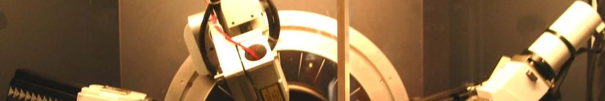
The goal of this project is to adapt the basic principles of operation of a powder X-ray
diffractometer and construct a simpler and safer diffractometer for students to use
built from LEGO® bricks. The theory behind both the LEGO® model and X-ray
diffractometers are almost the same. X-ray diffractometers are used to measure the
spacing between planes of atoms using the Bragg equation. X-rays are necessary
for the X-ray diffraction experiment because they have enough energy to easily
penetrate materials and they have a sufficiently small wavelength to be diffracted by
the small spacing between planes of atoms. The LEGO® model uses visible laser
light which is more safe than the X
light, X-rays
rays used in the powder X X-ray
ray diffractometer
diffractometer.
The LEGO® model uses a NXT module connected to a motor to rotate an arm on
which a light sensor is mounted. After construction of the LEGO® model and
programming of the NXT module, its laser can be used to find the spacing between
the rows of a diffraction grating. To do this, laser light is shined through the
diffraction grating and the sensor arm is rotated through the path of light diffracted
from the grating. The data is extracted from the NXT and Microsoft® Office Excel®
is used to graph light intensity as a function of sensor angle. The angle between the
1
light intensity peaks in the graph can be used in the Fraunhofer equation to find the
spacing between the rows of the grating.
Parts List

Bricks:
1x4 = 2                  Note: A full Mindstorms® NXT
                         kit (#8527) is required for this
1x8 = 1                  instrument
2x2 = 4
2x4 = 6
2x8 = 1
                             Non-LEGO® Parts
Plates:
1x2 = 2
                         Electrical Tape
1x4 = 2
                         Diffraction Grating
2x4 = 3
                         Laser
Flat Tiles:
1x2 = 3
Bricks, with holes:
1x2
1x6
Cross axles:
m6 = 2
m8 = 2
Miscellaneous:
B Caps
Bar C          = 12
Connectors = 2                                              2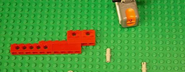
Motor Mount Construction

                           3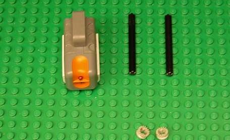
Grating Mount Construction

Note: Make sure the diffraction grating is aligned so the
grooves are parallel to the base and perpendicular to the axis
of rotation.
                                                                 4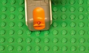
Arm and Sensor Construction

                   Note: The slit between the
                   pieces of electrical tape is
                   positioned in front of the top
                   sensor and reduces the overall
                   light intensity reaching the
                   sensor.

                                           5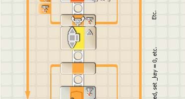
Sensor Support Construction    Swivel Support Construction

                 Laser Mount Construction

                                                       6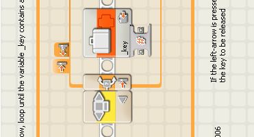
Support and Motor Placement

                              7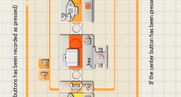
Arm and Grating Placement

                            8
NXT and Laser Placement
Beam path 9
Caution: Avoid direct eye exposure to laser beam.Incident and Diffracted Beam Path
Detector
First order light Source
LEGO Laser Diffractometer
Zeroth order light Incident laser beam
Incident X-ray
Powder X-ray Diffractometer
beam
Source Sample Stage Detector 10Programming
Note: Make sure that all wires are connected properly
between blocks!
111 2 3 4 5 6 7 8 9 10
1: Display, in text box type “select file #”
2: Display, in text box type “ to start”
3: Wait, NXT buttons
4: Rest Motor, designate which port the motor is plugged into
NXT
5: Get Number, subroutine (see page 14)
6: Number to Text
7: Text
8: File Access
Action: Close
9: File Access
Action: Delete
10: Motor
Power: 12 (for fully charged batteries; batteries with
lower charge require higher power settings)
Degrees: 50
Direction: down
Action: Constant 12
Make sure to designate which NXT port that the motor is
plugged into (e.g. A, B, C)1 2 3 4 5 6 7 8
1: Loop, select rotation sensor
2: Rotation Sensor, designate which port the motor is
plugged into
g Sensor, designate
3: Light g which p
port the sensor is p
plugged
gg
into, also to have the light side selected
4: Number to Text
5: Number to Text
6: Text
7: File Access
Action: Type
Type: Text
8: File Access
Action: Close
13GetNumber Subroutine Procedure
The GetNumber block will be the last block created in the code needed for
the diffractometer. After all other blocks are created, use the following
instructions
instructions.
• Create two number variables by clicking “Define Variables” under the
edit menu.
– Name them “_cursor” and “_result”
• Between the 4th and 5th blocks of the code, create 5 variable blocks
– Block 1 = Click “Number 1” in the list and set action to Read
– Block 2 = Click “Number 1” in the list and set action to Read
– Block 3 = Click “_result” in the list and set action to Write
– Block 4 = Click “_cursor” in the list and set action to Write
– Block 5 = Click “_result” in the list and set action to Read
• Make a connection from the left input of Block 3 to the input of Block 1
• Make a connection from the left input of Block 4 to the input of Block 2
• Make a connection between Block 5 and the left number input on the
Number-to-Text block immediately to the right
• Hold shift and click Block 3, Block 4, and Block 5 (referring to the newly
created variable blocks)
• Click “Make A New My Block” under the edit menu.
• Name the block “GetNumber”, click next, pick any picture you want,
then hit finish.
• The newly created custom block will be in place of Blocks 3, 4 and 5
• Delete the two variable blocks immediately before the newly created
block
• Double click on the GetNumber Block
• Rename the value plugs by double clicking on the name above the
plugs, and name them the following.
– Rename the plug connected to the first variable block as “seed”
– Rename the plug connected to the second variable block as
curLoc
“curLoc”
– Rename the plug connected to the third variable block as “Result”
• To complete the code for the “GetNumber” block, follow the following
GetNumber diagrams and create the remaining blocks between the
second and third variable blocks.
• After the GetNumber block is completed, you must delete, then re-add
the number block to the original code in order to apply the changes you
have made.
14G Key,
Get
subroutine
(see
e page 16)
Gett Number,
Subroutine
15Get Key, ssubroutine 16
Downloading Program to NXT from a Computer

  Press indicated button to
  download the program to the
  NXT

                 Running the Program from the NXT

 Press the orange square button. Then select a number for file name
 and press the orange button again. Now select “R” and press the
 orange button to run.

    Note: Keep hands away from the sensor arm because getting
    the arm caught could damage the motor.

             How to Upload NXT Data to a Computer

- Press indicated button
- Select Memory Tab
- Choose Other
- Highlight and Upload file number you assigned on the NXT
- Save file (Notepad document) to desired location
                                                                  17
- Open notepad document
                                                 Next page for analysis
Data Analysis
-Data will appear in a notepad document in the form of “angle, intensity”
-Copying and pasting these numbers into an Microsoft Excel will NOT
work. Instead, open the notepad document from within Excel
-Make sure to have “All files” selected in the “Types of files” pull
down menu in the “Open” window
Click “Open”
-Click Open and a window will appear called “Text
Text Import Wizard
Wizard”
-Make sure the “Delimited” radio button is selected, and click “Next”
-Check the “Comma” box and the window should demonstrate the
numbers separated into two columns, and click Finish
-With your data in two separate columns, they can be represented in a
graph to help you calculate your angle of diffraction
120
100
21°
80
ensity
60
Inte
40
20
0
0 10 20 30 40 50
Angle
- By starting the sensor below the zeroth order beam, your results will
indicate a peak for the beam path and a peak for the first order of
diffraction.
18
- The difference between these two numbers is the angle Ф.Calculations
The Fraunhofer equation can be used to calculate the
row repeat distance in the diffraction grating:
d x sin Ф = n x λ
where: d = row spacing
Ф = angle of diffraction
n = order of diffraction
λ = wavelength of light source
Sample Calculation
Ф = 21°
n=1
λ = 655 nm
d=?
d[sin(21°)] = 1(655 nm)
d = 1827 nm Diffraction grating spacing measured
by scanning electron microscopy is
approximately 1 8 m
1.8
19You can also read