SSDFS: Towards LFS Flash-Friendly File System without GC operations
←
→
Page content transcription
If your browser does not render page correctly, please read the page content below
SSDFS: Towards LFS Flash-Friendly File System without GC
operations
Viacheslav Dubeyko
arXiv:1907.11825v1 [cs.OS] 27 Jul 2019
Abstract to one. The typical latencies: (1) read operation - 20 us, (2)
write operation - 200 us, (3) erase operation - 2 ms.
Solid state drives have a number of interesting character-
Flash Translation Layer (FTL). FTL emulates the func-
istics. However, there are numerous file system and storage
tionality of a block device and enables operating system to
design issues for SSDs that impact the performance and de-
use flash memory without any modification. FTL mimics
vice endurance. Many flash-oriented and flash-friendly file
block storage interface and hides the internal complexities of
systems introduce significant write amplification issue and
flash memory to operating systems, thus enabling the oper-
GC overhead that results in shorter SSD lifetime and ne-
ating system to read/write flash memory in the same way as
cessity to use the NAND flash overprovisioning. SSDFS
reading/writing the hard disk. The basic function of FTL al-
file system introduces several authentic concepts and mech-
gorithm is to map the page number from logical to physical.
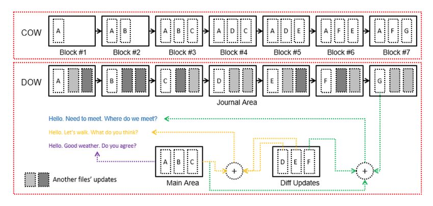
anisms: logical segment, logical extent, segment’s PEBs
However, internally FTL needs to deal with erase-before-
pool, Main/Diff/Journal areas in the PEB’s log, Diff-On-
write, which makes it critical to overall performance and life-
Write approach, PEBs migration scheme, hot/warm data
time of SSD.
self-migration, segment bitmap, hybrid b-tree, shared dic-
tionary b-tree, shared extents b-tree. Combination of all sug- Garbage Collection and Wear Leveling. The process of
gested concepts are able: (1) manage write amplification in collecting, moving of valid data and erasing the invalid data
smart way, (2) decrease GC overhead, (3) prolong SSD life- is called as garbage collection. Through SSD firmware com-
time, and (4) provide predictable file system’s performance. mand TRIM the garbage collection is triggered for deleted
file blocks by the file system. Commonly used erase blocks
Index terms: NAND flash, SSD, Log-structured file
puts off quickly, slows down access times and finally burn-
system (LFS), write amplification issue, GC overhead,
ing out. Therefore the erase count of each erase block should
flash-friendly file system, SSDFS, delta-encoding, Copy-
be monitored. There are wide number of wear-leveling tech-
On-Write (COW), Diff-On-Write (DOW), PEB migra-
niques used in FTL.
tion, deduplication.
Building blocks of SSD. SSD includes a controller that
incorporates the electronics that bridge the NAND memory
1 INTRODUCTION components to the host computer. The controller is an em-
bedded processor that executes firmware-level code. Some
Flash memory characteristics. Flash is available in two of the functions performed by the controller includes, error-
types NOR and NAND. NOR flash is directly addressable, correcting code (ECC), wear leveling, bad block mapping,
helps in reading but also in executing of instructions di- read scrubbing and read disturb management, read and write
rectly from the memory. NAND based SSD consists of set caching, garbage collection etc. A flash-based SSD typically
of blocks which are fixed in number and each block com- uses a small amount of DRAM as a cache, similar to the
prises of a fixed set of pages or whole pages set makes up cache in hard disk drives. A directory of block placement
a block. There are three types of operations in flash mem- and wear leveling data is also kept in the cache while the
ory: read, write and erase. Execution of operations read and drive is operating.
write takes place per page level. On the other hand the data Write amplification. For write requests that come in ran-
is erased on block level by using erase operation. Because dom order, after a period of time, the free page count in flash
of the physical feature of flash memory, write operations are memory becomes low. The garbage-collection mechanism
able to modify bits from one to zero. Hence the erase op- then identifies a victim block for cleaning. All valid pages
eration should be executed before rewriting as it set all bits in the victim block are relocated into a new block with free
1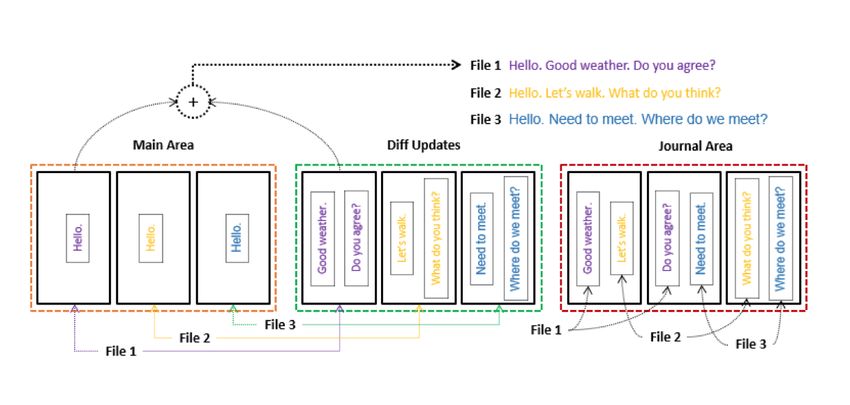
pages, and finally the candidate block is erased so that the          architecture and approaches. Section IV includes final dis-
pages become available for rewriting. This mechanism in-              cussion. Section V offers conclusions.
troduces additional read and write operations, the extent of
which depends on the specific policy deployed, as well as on
the system parameters. These additional writes result in the          2     RELATED WORKS
multiplication of user writes, a phenomenon referred to as
write amplification.                                                  2.1    File Systems Statistics and Analysis
   Read disturbance. Flash data block is composed of mul-             File size. Agrawal, et al. [10] discovered that 1-1.5% of files
tiple NAND units to which the memory cells are connected              on a file system’s volume have a size of zero. The arithmetic
in series. A memory operation on a specific flash cell will           mean file size was 108 KB in 2000 year and 189 KB in 2004
influence the charge contents on a different cells. This is           year. This metric grows roughly 15% per year. The median
called disturbance, which can occur on any flash operation            weighted file size increasing from 3 MB to 9 MB. Most of
and predominantly this is observed during the read operation          the bytes in large files are in video, database, and blob files,
and leads to errors in undesignated memory cells. To avoid            and that most of the video, database, and blob bytes are in
failure on reads, error-correcting codes (ECC) are widely             large files. A large number of small files account for a small
employed. Read disturbance can occur when reading the                 fraction of disk usage. Douceur, et al. [12] confirmed that
same target cell multiple times without an erase and pro-             1.7% of all files have a size of zero. The mean file size ranges
gram operation. In general, to preserve data consistency,             from 64 kB to 128 kB across the middle two quartiles of all
flash firmware reads all live data pages, erases the block, and       file systems. The median size is 2 MB and it confirms that
writes down the live pages to the erased block. This process,         most files are small but most bytes are in large files. Ullah,
called read block reclaiming, introduces long latencies and           et al. [16] have results about 1 to 10 KB the value observed
degrades performance.                                                 is up to 32% of the total occurrences. There are 29% values
   SSD design issues. Solid state drives have a number                in the range of 10 KB to 100 KB. Gibson, et al. [17] agreed
of interesting characteristics that change the access pat-            that most files are relatively small, more than half are less
terns required to optimize metrics such as disk lifetime and          than 8 KB. 80% or more of the files are smaller than 32 KB.
read/write throughput. In particular, SSDs have approxi-              On the other hand, while only 25% are larger than 8 KB, this
mately two orders of magnitude improvement in read and                25% contains the majority of the bytes used on the different
write latencies, as well as a significant increase in overall         systems.
bandwidth. However, there are numerous file system and                   File age. Agrawal, et al. [10] stated that the median file
storage array design issues for SSDs that impact the perfor-          age ranges between 80 and 160 days across datasets, with no
mance and device endurance. SSDs suffer well-documented               clear trend over time. Douceur, et al. [12] has the vision of
shortcomings: log-on-log, large tail-latencies, unpredictable         the median file age is 48 days. Studies of short-term trace
I/O latency, and resource underutilization. These shortcom-           data have shown that the vast majority of files are deleted
ings are not due to hardware limitations: the non-volatile            within a few minutes of their creation. On 50% of file sys-
memory chips at the core of SSDs provide predictable high-            tems, the median file age ranges by a factor of 8 from 12 to 97
performance at the cost of constrained operations and limited         days, and on 90% of file systems, it ranges by a factor of 256
endurance/reliability. Providing the same block I/O interface         from 1.5 to 388 days. Gibson, et al. [17] showed that while
as a magnetic disk is one of the important reason of these            only 15% of the files are modified daily, these modifications
drawbacks.                                                            account for over 70% of the bytes used daily. Relatively few
   SSDFS features. Many flash-oriented and flash-friendly             files are used on any one day normally less than 5%. 5-
file systems introduce significant write amplification issue          10% of all files created are only used on one day, depending
and GC overhead that results in shorter SSD lifetime and              on the system. On the other hand, approximately 0.8% of
necessity to use the NAND flash overprovisioning. SSDFS               the files are used more than 129 times essentially every day.
file system introduces several authentic concepts and mech-           These files which are used more than 129 times account for
anisms: logical segment, logical extent, segment’s PEBs               less than 1% of all files created and approximately 10% of
pool, Main/Diff/Journal areas in the PEB’s log, Diff-On-              all the files which were accessed or modified. 90% of all
Write approach, PEBs migration scheme, hot/warm data                  files are not used after initial creation, those that are used are
self-migration, segment bitmap, hybrid b-tree, shared dic-            normally short-lived, and that if a file is not used in some
tionary b-tree, shared extents b-tree. Combination of all sug-        manner the day after it is created, it will probably never be
gested concepts are able: (1) manage write amplification in           used. 1% of all files are used daily.
smart way, (2) decrease GC overhead, (3) prolong SSD life-               Files count per file system. Agrawal, et al. [10] showed
time, and (4) provide predictable file system’s performance.          that the count of files per file system is going up from year
   The rest of this paper is organized as follows. Section II         to year. The arithmetic mean has grown from 30K to 90K
surveys the related works. Section III explains the SSDFS             files and the median has grown from 18K to 52K files (2000

                                                                  2
- 2004 years). However, some percentage of file systems has directory depth has increased from 5 to 6. The count of files
achieved about 512K files already in 2004 year. Douceur, et per directory is mostly independent of directory depth. Files
al. [12] have vision that 31% of all file systems contain 8k to deeper in the namespace tree tend to be smaller than shal-
16k files. 30% of file systems have fewer than 4k files. Ullah, lower ones. The mean file size drops by two orders of mag-
et al. [16] found that 67% of the occurrences are found in the nitude between depth 1 and depth 3, and there is a drop of
range of 1-8 number of files in a directory. The percentage roughly 10% per depth level thereafter.
of the 9-16 files in a directory comprises of 15% of the total Capacity and usage. Agrawal, et al. [10] registered that
data found. The number of file in the range 17-32 are 9% 80% of file systems become fuller over a one-year period,
and only 9% occurrences are found in the data more than 32 and the mean increase in fullness is 14 percentage points.
files in a directory. This increase is predominantly due to creation of new files,
File names. Agrawal, et al. [10] made conclusion that dy- partly offset by deletion of old files, rather than due to extant
namic link libraries (dll files) contain more bytes than any files changing size. The space used in file systems has in-
other file type. And virtual hard drives are consuming a creased not only because mean file size has increased (from
rapidly increasing fraction of file-system space. Ullah, et 108 KB to 189 KB), but also because the number of files has
al. [16] discovered that the file name length falls in the range increased (from 30K to 90K). Douceur, et al. [12] discovered
from 9 to 17 characters. The peak occurs for file names with that file systems are on average only half full, and their full-
length of 12 characters. The file names smaller than 8 char- ness is largely independent of user job category. On average,
acters are up to 11% of the total data collected whereas the half of the files in a file system have been created by copy-
occurrences of file names larger than 16 characters and up ing without subsequent writes, and this is also independent
to 32 characters is 26% but the file names greater than 32 of user job category. The mean space usage is 53%.
characters are found to be only 6%. A File Is Not a File. Harter, et al. [14] showed that
Directory size. Agrawal, et al. [10] discovered that across modern applications manage large databases of information
all years, 23-25% of directories contain no files. The arith- organized into complex directory trees. Even simple word-
metic mean directory size has decreased slightly and steadily processing documents, which appear to users as a ”file”, are
from 12.5 to 10.2 over the sample period, but the median di- in actuality small file systems containing many sub-files.
rectory size has remained steady at 2 files. Across all years, Auxiliary files dominate. Tan, et al. [13] discovered that
65-67% of directories contain no subdirectories. Across all on iOS, applications access resource, temp, and plist files
years, 46-49% of directories contain two or fewer entries. very often. This is especially true for Facebook which uses a
Douceur, et al. [12] shared that 18% of all directories con- large number of cache files. Also for iOS resource files such
tain no files and the median directory size is 2 files. 69% as icons and thumbnails are stored individually on the file
of all directories contain no subdirectories, 16% contain one, system. Harter, et al. [14] agree with that statement. Appli-
and fewer than 0.5% contain more than twenty. On 50% of cations help users create, modify, and organize content, but
file systems, the median directory size ranges from 1 to 4 user files represent a small fraction of the files touched by
files, and on 90% of file systems, it ranges from 0 to 7 files. modern applications. Most files are helper files that appli-
On 95% of all file systems, the median count of subdirecto- cations use to provide a rich graphical experience, support
ries per directory is zero. 15% of all directories are at depth multiple languages, and record history and other metadata.
of 8 or greater. Sequential Access Is Not Sequential. Harter, et al. [14]
Directories count per file system. Agrawal, et al. [10] stated that even for streaming media workloads, ”pure” se-
registered that the count of directories per file system has quential access is increasingly rare. Since file formats often
increased steadily over five-year sample period. The arith- include metadata in headers, applications often read and re-
metic mean has grown from 2400 to 8900 directories and the read the first portion of a file before streaming through its
median has grown from 1K to 4K directories. Douceur, et contents.
al. [12] shared that 28% of all file systems contain 512 to Writes are forced. Tan, et al. [13] shared that on iOS,
1023 directories, and 29% of file systems have fewer than Facebook calls fsync even on cache files, resulting in the
256 directories. Ullah, et al. [16] shared that 59% of the largest number of fsync calls out of the applications. On
directories have sub-directories in the range of 1-5, 35% oc- Android, fsync is called for each temporary write-ahead log-
currences are found in the range of 6-10. But the results show ging journal files. Harter, et al. [14] found that applications
that only 6% occurrences are found in the range of above 10 are less willing to simply write data and hope it is eventually
sub-directories in a directory. flushed to disk. Most written data is explicitly forced to disk
Namespace tree depth. Agrawal, et al. [10] shared that by the application; for example, iPhoto calls fsync thousands
there are many files deep in the namespace tree, especially of times in even the simplest of tasks.
at depth 7. Also, files deeper in the namespace tree tend Temporary files. Tan, et al. [13] showed that applications
to be orders-of-magnitude smaller than shallower files. The create many temporary files. It might have a negative impact
arithmetic mean has grown from 6.1 to 6.9, and the median on the durability of the flash storage device. Also, creat-
3ing many files result in storage fragmentation. The SQLite occur are due to I/O libraries and high-level abstractions.
database library creates many short-lived temporary journal File System and Block IO Scheduler. Hui, et al. [20]
files and calls fsync often. have made the estimation of interaction between file sys-
Copied files. Agrawal, et al. [10] shared the interest- tems and block I/O scheduler. They concluded that more
ing point that over sample period (2000 - 2004), the arith- read or append-write may cause better performance and less
metic mean of the percentage of copied files has grown from energy consumption, such as in the workload of the web-
66% to 76%, and the median has grown from 70% to 78%. server. And along with the increasing of the write operation,
It means that more and more files are being copied across especially random write, the performance declines and en-
file systems rather than generated locally. Downey [15] con- ergy consumption increases. The extent file systems express
cluded that the vast majority of files in most file systems were better performance and lower energy consumption. They ex-
created by copying, either by installing software (operating pected that NOOP I/O scheduler is better suit for the case
system and applications) or by downloading from the World of SSDs because it does not sort the request, which can cost
Wide Web. Many new files are created by translating a file much time and decline performance. But after the test, they
from one format to another, compiling, or by filtering an ex- found that as CFQ as NOOP may be suit for the SSDs.
isting file. Using a text editor or word processor, users add NAND flash storage device. Parthey, et al. [21] analyzed
or remove material from existing files, sometimes replacing access timing of removable flash media. They found that
the original file and sometimes creating a series of versions. many media access address zero especially fast. For some
Renaming Is Popular. Harter, et al. [14] discovered that media, other locations such as the middle of the medium are
home-user applications commonly use atomic operations, in sometimes slower than the average. Accessing very small
particular rename, to present a consistent view of files to blocks (≤2 KiB) can be prohibitively slow. This is not the
users. result of normal overhead increase for small blocks but some
Multiple Threads Perform I/O. Harter, et al. [14] kind of irregularity, e.g. due to inadequate management
showed that virtually all of the applications issue I/O re- mechanisms. The written bit pattern also influences access
quests from a number of threads; a few applications launch timing, but to a lesser degree. The overwritten value is irrel-
I/Os from hundreds of threads. Part of this usage stems from evant. The value of irregular behavior is usually 0xff. Some-
the GUI-based nature of these applications; threads are re- times, writing 0xff is a bit faster than all other bit patterns, in
quired to perform long-latency operations in the background rare cases it requires considerably more access time.
to keep the GUI responsive. Son, et al. [22] have made an empirical evaluation of
Frameworks Influence I/O. Harter, et al. [14] found NVM Express SSDs. Read performance of NVMe shows
that modern applications are often developed in sophisticated very good scalability with respect to the number of threads
IDEs and leverage powerful libraries, such as Cocoa and since the NVMe and SSD controller fully exploit the SSD
Carbon. Whereas UNIX-style applications often directly in- channel parallelism. As the number of threads is increased,
voke system calls to read and write files, modern libraries the throughput is improved almost linearly until the number
put more code between applications and the underlying file of threads is 128. In case of 256 threads, the throughput is
system. Default behavior of some Cocoa APIs induces ex- saturated at about 2.5GB/s (625K IOPS), which is a peak
tra I/O and possibly unnecessary (and costly) synchroniza- throughput for NVMe SSD. The latency also increases al-
tions to disk. In addition, use of different libraries for similar most linearly as the throughput is increased until the number
tasks within an application can lead to inconsistent behavior of threads is 256. However, write operations show limited
between those tasks. scalability despite the intended scalable design of NVMe be-
Applications’ behavior. Harter, et al. [14] made several cause it is limited by the flash characteristics. The perfor-
conclusions about applications’ nature. Applications tend to mance is increased only marginally in case of more than 16
open many very small files (1 MB). The vast majority of I/O tency reaches up to 4500us and the larger number of threads
is performed by reading and writing to open file descriptors. only increases contentions among threads and GC overhead.
Only a few of the iBench tasks have significant pageins from The results demonstrate that random read performance of
memory-mapped files; most of this pagein traffic is from im- NVMe SSD is dependent on both the number of cores and
ages. Applications perform large numbers of very small (≤4 threads. For random write of NVMe SSD like random read
KB) reads and writes. Metadata accesses are very common, case, overall performance increases as the number of cores
greatly outnumbering accesses to file data across all of inves- increases. In both read and write cases the performance
tigated workloads. A moderate amount of reads could poten- of NVMe SSD is dependent on the number of cores and
tially be serviced by a cache, but most reads are to fresh data. reaches the peak performance when the number of cores is
Written data is rarely over-written, so waiting to flush buffers enough. NVMe SSD provides as many I/O queues as the
until data becomes irrelevant is usually not helpful. Many of number of CPU cores to improve scalability and parallelism.
the reads and writes to previously accessed data which do The impact by the number of queues is less consistent due
4to performance variation in write operation when compared isfying read requests. As a result, disk traffic will become
to the random read case but it clearly shows that the maxi- dominated by writes. A log-structured file system writes
mum performance is lower when only one I/O queue is used. all new information to disk in a sequential structure called
Fsync operation dramatically lowers the write performance the log. This approach increases write performance dramat-
of NVMe SSD. In case of sequential write, one fsync per ically by eliminating almost all seeks. The sequential nature
write operation drops the write performance by 47.2% com- of the log also permits much faster crash recovery: current
pared to no fsync per operation. As the number of fsync Unix file systems typically must scan the entire disk to re-
decreases, the performance gradually increases. Fsync calls store consistency after a crash, but a log-structured file sys-
have more influence on random write performance than on tem need only examine the most recent portion of the log.
sequential write performance. There is almost no perfor- For a log-structured file system to operate efficiently, it must
mance improvement even if the number of fsync calls is de- ensure that there are always large extents of free space avail-
creased with random write operations, which means fsync able for writing new data. This is the most difficult challenge
call limits random write performance to the greater extent. in the design of a log-structured file system. It was presented
NVMe SSD with low latency does not benefit from using a solution based on large extents called segments, where a
large page sizes for I/O operations. segment cleaner process continually regenerates empty seg-
Zhou, et al. [23] concluded that when the file systems ments by compressing the live data from heavily fragmented
block size is the same as the SSD page size, the SSD would segments.
deliver best performance. This is because writes matching
the underlying page size would generally avoid partial page
updating/overwriting and correspondingly improve garbage 2.3 Flash-oriented File Systems
collection efficiency. SSD would exhibit better performance JFFS (The Journalling Flash File System) [35, 36] is a
when used in a log-style way. Allocation group is a unique purely log-structured file system [LFS]. Nodes containing
feature to XFS file system. Intuitively, the more allocation data and metadata are stored on the flash chips sequentially,
group the file system has, the better performance it would progressing strictly linearly through the storage space avail-
deliver. For smaller degree of allocation group (16 alloca- able. In JFFS v1, there is only one type of node in the log;
tion group), each allocation group is relatively larger and it is a structure known as struct jffs raw inode. Each such node
very likely that the workload only exercises only part of one is associated with a single inode. It starts with a common
certain allocation group which occupies only one plane, for header containing the inode number of the inode to which it
example, and the performance suffers. For moderate degree belongs and all the current file system metadata for that in-
of allocation group (32 and 64 allocation group), the work- ode, and may also carry a variable amount of data. There is
ing files are distributed among the allocation groups and the a total ordering between the all the nodes belonging to any
internal parallelism helps to improve performance. But when individual inode, which is maintained by storing a version
the allocation group is too large, then parallelism contribu- number in each node. Each node is written with a version
tion disappears due to the aggressive contention for shared higher than all previous nodes belonging to the same inode.
resources, like shared data buses, connecting circuitry. When In addition to the normal inode metadata such as uid, gid,
the file system block size matches the I/O request size, the mtime, atime, mtime etc., each JFFS v1 raw node also con-
performance is consistently better than the other combina- tains the name of the inode to which it belongs and the inode
tions. number of the parent inode. Each node may also contain
an amount of data, and if data are present the node will also
2.2 Log-Structured File System record the offset in the file at which these data should appear.
The entire medium is scanned at mount time, each node be-
Rosenblum, et al. [34] introduced a new technique for disk ing read and interpreted. The data stored in the raw nodes
storage management called a log-structured file system. A provide sufficient information to rebuild the entire directory
log-structured file system writes all modifications to disk se- hierarchy and a complete map for each inode of the physi-
quentially in a log-like structure, thereby speeding up both cal location on the medium of each range of data. Metadata
file writing and crash recovery. The log is the only struc- changes such as ownership or permissions changes are per-
ture on disk; it contains indexing information so that files formed by simply writing a new node to the end of the log
can be read back from the log efficiently. In order to main- recording the appropriate new metadata. File writes are sim-
tain large free areas on disk for fast writing, they divided the ilar; differing only in that the node written will have data
log into segments and use a segment cleaner to compress the associated with it.
live information from heavily fragmented segments. Log- The oldest node in the log is known as the head, and new
structured file systems are based on the assumption that files nodes are added to the tail of the log. In a clean filesys-
are cached in main memory and that increasing memory tem which on which garbage collection has never been trig-
sizes will make the caches more and more effective at sat- gered, the head of the log will be at the very beginning of the
5flash. As the tail approaches the end of the flash, garbage col- collectors to read eraseblocks directly and determine what
lection will be triggered to make space. Garbage collection data needs to be moved and what can be discarded, and to
will happen either in the context of a kernel thread which at- update their indexes accordingly. The combination of data
tempts to make space before it is actually required, or in the and metadata is called a node. Each node records which file
context of a user process which finds insufficient free space (more specifically inode number) that the node belongs to
on the medium to perform a requested write. In either case, and what data (for example file offset and data length) is
garbage collection will only continue if there is dirty space contained in the node. The big difference between JFFS2
which can be reclaimed. If there is not enough dirty space to and UBIFS is that UBIFS stores the index on flash whereas
ensure that garbage collection will improve the situation, the JFFS2 stores the index only in main memory, rebuilding it
kernel thread will sleep, and writes will fail with ENOSPC when the file system is mounted. Potentially that places a
errors. The goal of the garbage collection code is to erase the limit on the maximum size of a JFFS2 file system, because
first flash block in the log. At each pass, the node at the head the mount time and memory usage grow linearly with the
of the log is examined. If the node is obsolete, it is skipped size of the flash. UBIFS was designed specifically to over-
and the head moves on to the next node. If the node is still come that limitation.
valid, it must be rendered obsolete. The garbage collection The master node stores the position of all on-flash struc-
code does so by writing out a new data or metadata node to tures that are not at fixed logical positions. The master node
the tail of the log. itself is written repeatedly to logical eraseblocks (LEBs) one
While the original JFFS had only one type of node on the and two. LEBs are an abstraction created by UBI. UBI maps
medium, JFFS2 is more flexible, allowing new types of node physical eraseblocks (PEBs) to LEBs, so LEB one and two
to be defined while retaining backward compatibility through can be anywhere on the flash media (strictly speaking, the
use of a scheme inspired by the compatibility bitmasks of UBI device), however UBI always records where they are.
the ext2 file system. Every type of node starts with a com- Two eraseblocks are used in order to keep two copies of
mon header containing the full node length, node type and a the master node. This is done for the purpose of recovery,
cyclic redundancy checksum (CRC). Aside from the differ- because there are two situations that can cause a corrupt or
ences in the individual nodes, the high-level layout of JFFS2 missing master node. LEB zero stores the superblock node.
also changed from a single circular log format, because of The superblock node contains file system parameters that
the problem caused by strictly garbage collecting in order. change rarely if at all. For example, the flash geometry
In JFFS2, each erase block is treated individually, and nodes (eraseblock size, number of eraseblocks etc) is stored in the
may not overlap erase block boundaries as they did in the superblock node. The other UBIFS areas are: the log area
original JFFS. This means that the garbage collection code (or simply the log), the LEB properties tree (LPT) area, the
can work with increased efficiency by collecting from one orphan area and the main area. The log is a part of UBIFS’s
block at a time and making intelligent decisions about which journal.
block to garbage collect from next. The purpose of the UBIFS journal is to reduce the fre-
In traditional file systems the index is usually kept and quency of updates to the on-flash index. The index consists
maintained on the media, but unfortunately, this is not the of the top part of the wandering tree that is made up of only
case for JFFS2. In JFFS2, the index is maintained in RAM, index nodes, and that to update the file system a leaf node
not on the flash media. And this is the root of all the JFFS2 must be added or replaced in the wandering tree and all the
scalability problems. Of course, having the index in RAM ancestral index nodes updated accordingly. It would be very
JFFS2 achieves extremely high file system throughput, just inefficient if the on-flash index were updated every time a
because it does not need to update the index on flash after leaf node was written, because many of the same index nodes
something has been changed in the file system. And this would be written repeatedly, particularly towards the top of
works very well for relatively small flashes, for which JFFS2 the tree. Instead, UBIFS defines a journal where leaf nodes
was originally designed. But as soon as one tries to use are written but not immediately added to the on-flash index.
JFFS2 on large flashes (starting from about 128MB), many Note that the index in memory (see TNC) is updated. Peri-
problems come up. JFFS2 needs to build the index in RAM odically, when the journal is considered reasonably full, it is
when it mounts the file system. For this reason, it needs to committed. The commit process consists of writing the new
scan the whole partition in order to locate all the nodes which version of the index and the corresponding master node.
are present there. So, the larger is JFFS2 partition, the more After the log area, comes the LPT area. The size of the
nodes it has, the longer it takes to mount it. The second, it log area is defined when the file system is created and conse-
is evidently that the index consumes some RAM. And the quently so is the start of the LPT area. At present, the size of
larger is the JFFS2 file system, the more nodes it has, the the LPT area is automatically calculated based on the LEB
more memory is consumed. size and maximum LEB count specified when the file sys-
UBIFS (Unsorted Block Image File System) [37, 38] tem is created. Like the log area, the LPT area must never
follows a node-structured design, that enables their garbage run out of space. Unlike the log area, updates to the LPT
6area are not sequential in nature - they are random. In addi- flash may be shipped with bad blocks and further blocks
tion, the amount of LEB properties data is potentially quite may go bad during the operation of the device. Thus, Yaffs
large and access to it must be scalable. The solution is to is aware of bad blocks and needs to be able to detect and
store LEB properties in a wandering tree. In fact the LPT mark bad blocks. NAND flash also typically requires the use
area is much like a miniature file system in its own right. It of some sort of error detection and correction code (ECC).
has its own LEB properties - that is, the LEB properties of Yaffs can either use existing ECC logic or provide its own.
the LEB properties area (called ltab). It has its own form of Yaffs2 has a true log structure. A true log structured file
garbage collection. It has its own node structure that packs system only ever writes sequentially. Instead of writing data
the nodes as tightly as possible into bit-fields. However, like in locations specific to the files, the file system data is written
the index, the LPT area is updated only during commit. Thus in the form of a sequential log. The entries in the log are all
the on-flash index and the on-flash LPT represent what the one chunk in size and can hold one of two types of chunk:
file system looked like as at the last commit. The difference (1) Data chunk - a chunk holding regular data file contents,
between that and the actual state of the file system, is repre- (2) Object Header - a descriptor for an object (directory, reg-
sented by the nodes in the journal. ular data file, hard link, soft link, special descriptor,...). This
The next UBIFS area to describe is the orphan area. An holds details such as the identifier for the parent directory,
orphan is an inode number whose inode node has been com- object name, etc. Each chunk has tags associated with it. The
mitted to the index with a link count of zero. That happens tags comprise the following important fields: (1) ObjectId -
when an open file is deleted (unlinked) and then a commit identifies which object the chunk belongs to, (2) ChunkId -
is run. In the normal course of events the inode would be identifies where in the file this chunk belongs, (3) Deletion
deleted when the file is closed. However in the case of an Marker - (Yaffs1 only) shows that this chunk is no longer in
unclean unmount, orphans need to be accounted for. After an use, (4) Byte Count - number of bytes of data if this is a data
unclean unmount, the orphans’ inodes must be deleted which chunk, (5) Serial Number - (Yaffs1 only) serial number used
means either scanning the entire index looking for them, or to differentiate chunks with the same objectId and chunkId.
keeping a list on flash somewhere. UBIFS implements the When a block is made up only of deleted chunks, that
latter approach. block can be erased and reused. However, it needs to copy
The final UBIFS area is the main area. The main area the valid data chunks off a block, deleting the originals
contains the nodes that make up the file system data and the and allowing the block to be erased and reused. This pro-
index. A main area LEB may be an index eraseblock or a cess is referred to as garbage collection. If garbage collec-
non-index eraseblock. A non-index eraseblock may be a bud tion is aggressive, the whole block is collected in a single
(part of the journal) or have been committed. A bud may be garbage collection cycle. If the collection is passive then
currently one of the journal heads. A LEB that contains com- the number of copies is reduced thus spreading the effort
mitted nodes can still become a bud if it has free space. Thus over many garbage collection cycles. This is done to reduce
a bud LEB has an offset from which journal nodes begin, garbage collection load and improve responsiveness. The ra-
although that offset is usually zero. tionale behind the above heuristics is to delay garbage col-
There are three important differences between UBIFS and lection when possible to reduce the amount of collection that
JFFS2. The first has already been mentioned: UBIFS has an needs to be performed, thus increasing average system per-
on-flash index, JFFS2 does not - thus UBIFS is potentially formance. Yet there is a conflicting goal of trying to spread
scalable. The second difference is implied: UBIFS runs on the garbage collection so that it does not all happen at the
top of the UBI layer which runs on top of the MTD subsys- same causing fluctuations in file system throughput. These
tem, whereas JFFS2 runs directly over MTD. UBIFS bene- conflicting goals make garbage tuning quite challenging.
fits from the wear-leveling and error handling of UBI at the Mount scanning takes quite a lot of time and slows mount-
cost of the flash space, memory and other resources taken ing. Checkpointing is a mechanism to speed the mounting
by UBI. The third important difference is that UBIFS allows by taking a snapshot of the Yaffs runtime state at unmount
writeback. or sync() and then reconstituting the runtime state on re-
Yaffs (Yet Another Flash File System) [39] contains ob- mounting. The actual checkpoint mechanism is quite sim-
jects. The object is anything that is stored in the file system. ple. A stream of data is written to a set of blocks which are
These are: (1) Regular data files, (2) Directories, (3) Hard- marked as holding checkpoint data and the important run-
links, (4) Symbolic links, (5) Special objects (pipes, devices time state is written to the stream.
etc). All objects are identified by a unique integer object NAFS (NAND flash memory Array File System) [46]
Id. In Yaffs, the unit of allocation is the chunk. Typically a consists of a Conventional File System and the NAND Flash
chunk will be the same as a NAND page, but there is flexi- Memory Array Interface; the former provides the users with
bility to use chunks which map to multiple pages. basic file operations while the latter allows concurrent ac-
Many, typically 32 to 128 but as many as a few hundred, cesses to multiple NAND flash memories through a striping
chunks form a block. A block is the unit of erasure. NAND technique in order to increase I/O performance. Also, parity
7bits are distributed across all flash memories in the array to data in the segment unit rather than in the page unit, NAMU’s
provide fault tolerance like RAID5. memory usage efficiency is better than JFFS2’s, YAFFS2’s.
The NAND flash memory is partitioned into two areas: MNFS (novel mobile multimedia file system) [50] intro-
one for the superblock addresses and the other for the su- duces (1) hybrid mapping, (2) block-based file allocation, (3)
perblock itself, inodes, and data. In order to provide uniform an in-core only Block Allocation Table (iBAT), and (4) up-
wear-leveling, the superblock is stored at the random loca- ward directory representation. Using these methods, MNFS
tion in the Data/Superblock/Inode-block Partition while its achieves uniform write-responses, quick mounting, and a
address is stored in the Superblock Address Partition. NAFS small memory footprint.
attempts to write file data consecutively into each block of The hybrid mapping scheme means that MNFS uses a
NAND flash memory for better read and write performance. page mapping scheme (log-structured method) for the meta-
In addition, NAFS adopts a new double list cache scheme data by virtue of the frequent updates. On the other hand,
that takes into account the characteristics of both large- a block mapping scheme is used for user data, because it
capacity storage and NAND flash memory in order to in- is rarely updated in mobile multimedia devices. The entire
crease I/O performance. The double list cache makes it pos- flash memory space is logically divided into two variable-
sible to defer write operations and increase the cache hit ratio sized areas: the Metadata area and the User data area.
by prefetching relevant pages through data striping of NAND MNFS uses a log structure to manage the file system meta-
Flash Memory Array Interface. The double list cache con- data. The metadata area is a collection of log blocks that con-
sists of the clean list for the actual caching and the dirty list tain file system metadata; the page mapping scheme is used
for monitoring and analyzing page reference patterns. The for this area. The user data area is a collection of data blocks
dirty list maintains dirty pages in order to reduce their search that contains multimedia file data; the block mapping scheme
times, and the clean list maintains clean pages. All the pages is used for this area. A multimedia file, e.g. a music or video
that are brought into memory by read operations are inserted clip, is an order of magnitude larger than the text-based file.
into the clean list. If clean pages in the clean list are modified Therefore, MNFS uses a larger allocation unit than the block
by write operations, they are removed from the clean list and size (usually 4 Kbytes) typically found in a legacy general
inserted into the head of the dirty list. Also, if a new file is purpose file system. MNFS defines the allocation unit of the
created, its new pages are inserted into the head of the dirty file system as a block of NAND flash memory. The block
list. If a page fault occurs, clean pages are removed from the size of NAND flash memory ranges from 16 Kbyte to 128
tail of the clean list. Kbyte, and this size is device specific.
When NAFS performs delayed write operations using the MNFS uses the iBAT, which is similar to the File Allo-
cache, since two blocks are assigned to each NAND flash cation Table in the FAT file system, for both uniform write-
memory, it is always guaranteed that a file data can be written responses and for robustness of the file system. There are
contiguously within at least one block. In addition, NAFS two important differences between the FAT and the iBAT.
performs delayed write operations in the dirty list, resulting First, the iBAT is not stored in the flash memory. Like the
in reduction of the number of write operations and consec- in-memory tree structure in YAFFS, the iBAT is dynami-
utive write operations of file data in each block of NAND cally constructed, during the mount time, in the main mem-
flash memory. ory (RAM) through scanning the spare area of all the blocks.
CFFS (Core Flash File System) [49], which is another Secondly, the iBAT uses block-based allocation whereas the
file system based on YAFFS, stores index entries and meta- FAT uses cluster-based allocation. In the FAT file system,
data into index blocks which are distinct from data blocks. as the file size grows, a new cluster is allocated, requiring
Since CFFS just reads in the index blocks during mount, its modification of the file allocation table in the storage de-
mount time is faster than YAFFS2’s. Furthermore, since fre- vice. Access to the storage device for the metadata update
quently modified metadata are collected and stored into in- not only affects the response time of the write request, but
dex blocks, garbage collection performance of CFFS is bet- it can also invoke file system inconsistency when the system
ter than YAFFS2’s. However, since CFFS stores the physical crashes during the update. In MNFS, the iBAT is not stored
addresses of index blocks into the first block of NAND flash separately in the flash memory, and the block allocation in-
memory in order to reduce mount time, wear-leveling perfor- formation is stored in the spare area of the block itself while
mance of CFFS is worse than others due to frequent erasure the block is allocated to a file. These two differences make
of the first block. MNFS more robust than the FAT file system.
NAMU (NAnd flash Multimedia file system) [48] takes MNFS uses upward directory representation method. In
into consideration the characteristics of both NAND flash this method, each directory entry in the log block has its par-
memory and multimedia files. NAMU utilizes an index ent directory entry ID. That is, the child entry points to its
structure that is suitable for large-capacity files to shorten parent entry. The directory structure of the file system can be
the mount time by scanning only index blocks located in the represented using this parent directory entry ID. For the up-
index area during mount. In addition, since NAMU manages ward directory representation method, it is necessary to read
8all of the directory entries in order to construct the directory placed on the last tail of the partial segment. The checkpoint
structure of the file system in the memory. includes a checksum of the checkpoint itself. The checkpoint
accuracy means successfully writing the partial segment to
the disk. The most important information in the checkpoint
2.4 Flash-friendly File Systems is the root block number of the inode block B-tree. The block
NILFS (New Implementation of a Log-structured File number is written out last, and the whole file system state is
System) [40, 41] has the on-disk layout is divided into sev- updated.
eral parts: (1) superblock, (2) full segment, (3) partial seg- The data write process started by the sync system call and
ment, (4) logical segment, (5) segment management block. NILFS kernel thread, advances in the following order: (1)
Superblock has the parameters of the file system, the disk Lock the directory operations, (2) The dirty pages of the file
block address of the latest segment being written, etc. Each data are gathered from its radix-tree, (3) The dirty B-tree in-
full segment consists of a fixed length of disk blocks. This termediate node pages of both file block management and
is a basic management unit of the garbage collector. Partial inode management are gathered, (4) The dirty inode block
segment is write units. Dirty buffers are written out as par- pages are gathered, (5) The B-tree intermediate node pages
tial segments. The partial segment does not exceed the full which will be dirty for registered block address being renew
segment boundaries. The partial segment sequence includes are gathered, (6) New disk block addresses are assigned to
inseparable directory operations. For example, a logical seg- those blocks in order of file data blocks, B-tree node blocks
ment could consist of two partial segments. In the recovery for file data, inode blocks, B-tree node blocks for inodes, (7)
operations, the two partial segments are treated as one insep- Rewrite the disk block addresses to new ones in the radix-
arable segment. There are two flag bits, Logical Begin and tree and B-tree nodes, (8) Call block device input/output rou-
Logical End, at the segment summary of the partial segment. tine to writing out the blocks, (9) Unlock the directory oper-
The NILFS adopts the B-tree structure for both file block ations. The NILFS snapshot is a whole consistent file system
mapping and inode block mapping. The two mappings are at some time instant.
implemented in the common B-tree operation routine. The In LFS, all blocks remain as is (until they are collected by
B-tree intermediate node is used to construct the B-tree. It garbage collection), therefore, no new information is needed
has 64-bit-wide key and 64-bit-wide pointer pairs. The file to make a snapshot. In NILFS, the B-tree structure manages
block B-tree uses a file block address as its key, whereas the the file and inode blocks, and B-tree nodes are written out as
inode block B-tree uses an inode number as its key. The root a log too. So, the root block number of the inode manage-
block number of the file block B-tree is stored to the corre- ment B-tree is the snapshot of the NILFS file system. The
sponding inode block. The root block number of the inode root block number is stored in the checkpoint position of a
block B-tree is stored to the superblock of the file system. partial segment. The NILFS checkpoint is the snapshot of the
So, there is only one inode block B-tree in the file system. file system itself. Actually, user can specify the disk block
File blocks, B-tree blocks for file block management, inode address of the NILFS checkpoint to Linux using the ”mount”
blocks, and B-tree blocks for inode management are written command, and the captured file system is mounted as a read-
to the disk as logs. A newly created file first exists only in only file system. However, when the user use all checkpoints
the memory page cache. Because the file must be accessible as the snapshot, there is no disk space for garbage collection.
before being written to the disk, the B-tree structure exists The user can select any checkpoint as a snapshot, and the
even in memory. The B-tree intermediate node in memory is garbage collector collects other checkpoint blocks.
on the memory page cache, the data structures are the same F2FS (Flash-Friendly File System) [43] employs three
as those of the disk blocks. The pointer of the B-tree node configurable units: segment, section and zone. It allocates
stored in memory holds the disk block number or the mem- storage blocks in the unit of segments from a number of in-
ory address of the page cache that reads the block. When dividual zones. It performs ”cleaning” in the unit of section.
looking up a block in the B-tree, if the pointer of the B-tree These units are introduced to align with the underlying FTL’s
node is a disk block number, the disk block is read into a operational units to avoid unnecessary (yet costly) data copy-
newly allocated page cache before the pointer is rewritten. ing.
The original disk block number remains in the buffer-head F2FS introduced a cost-effective index structure in the
structure on the page cache. form of node address table with the goal to attack the ”wan-
The partial segment consists of three parts: (1) The seg- dering tree” problem. Also multi-head logging was sug-
ment summary keeps the block usage information of the par- gested. F2FS uses an effective hot/cold data separation
tial segment. The main contents are checksums of the data scheme applied during logging time (i.e., block allocation
area, the segment summary, the length of the partial segment, time). It runs multiple active log segments concurrently and
and partial segment creation time. (2) Data area contains file appends data and metadata to separate log segments based
data blocks, file data B-tree node blocks, inode blocks, and on their anticipated update frequency. Since the flash stor-
inode block B-tree node blocks in order. (3) A checkpoint is age devices exploit media parallelism, multiple active seg-
9ments can run simultaneously without frequent management bolic link). A directory file constructs multi-level hash tables
operations. F2FS builds basically on append-only logging to manage a large number of dentries efficiently.
to turn random writes into sequential ones. At high stor- F2FS maintains six major log areas to maximize the ef-
age utilization, however, it changes the logging strategy to fect of hot and cold data separation. F2FS statically defines
threaded logging to avoid long write latency. In essence, three levels of temperaturehot, warm and coldfor node and
threaded logging writes new data to free space in a dirty seg- data blocks. Direct node blocks are considered hotter than
ment without cleaning it in the foreground. F2FS optimizes indirect node blocks since they are updated much more fre-
small synchronous writes to reduce the latency of fsync re- quently. Indirect node blocks contain node IDs and are writ-
quests, by minimizing required metadata writes and recover- ten only when a dedicated node block is added or removed.
ing synchronized data with an efficient roll-forward mecha- Direct node blocks and data blocks for directories are consid-
nism. ered hot, since they have obviously different write patterns
F2FS divides the whole volume into fixed-size segments. compared to blocks for regular files. Data blocks satisfying
The segment is a basic unit of management in F2FS and is one of the following three conditions are considered cold:
used to determine the initial file system metadata layout. A (1) Data blocks moved by cleaning, (2) Data blocks labeled
section is comprised of consecutive segments, and a zone ”cold” by the user, (3) Multimedia file data.
consists of a series of sections. F2FS splits the entire volume F2FS performs cleaning in two distinct manners, fore-
into six areas: (1) Superblock (SB), (2) Checkpoint (CP), (3) ground and background. Foreground cleaning is triggered
Segment Information Table (SIT), (4) Node Address Table only when there are not enough free sections, while a kernel
(NAT), (5) Segment Summary Area (SSA), (6) Main Area. thread wakes up periodically to conduct cleaning in back-
Superblock (SB) has the basic partition information and ground. A cleaning process takes three steps: (1) Victim
default parameters of F2FS, which are given at the format selection, (2) Valid block identification and migration, (3)
time and not changeable. Checkpoint (CP) keeps the file Post-cleaning process.
system status, bitmaps for valid NAT/SIT sets, orphan in- The cleaning process starts first to identify a victim sec-
ode lists and summary entries of currently active segments. tion among non-empty sections. There are two well-known
Segment Information Table (SIT) contains per-segment in- policies for victim selection during LFS cleaninggreedy and
formation such as the number of valid blocks and the bitmap cost-benefit. The greedy policy selects a section with the
for the validity of all blocks in the ”Main” area. The SIT in- smallest number of valid blocks. Intuitively, this policy con-
formation is retrieved to select victim segments and identify trols overheads of migrating valid blocks. F2FS adopts the
valid blocks in them during the cleaning process. Node Ad- greedy policy for its foreground cleaning to minimize the
dress Table (NAT) is a block address table to locate all the latency visible to applications. Moreover, F2FS reserves a
”node blocks” stored in the Main area. Segment Summary small unused capacity (5% of the storage space by default)
Area (SSA) stores summary entries representing the owner so that the cleaning process has room for adequate opera-
information of all blocks in the Main area, such as parent in- tion at high storage utilization levels. On the other hand,
ode number and its node/data offsets. The SSA entries iden- the cost-benefit policy is practiced in the background clean-
tify parent node blocks before migrating valid blocks during ing process of F2FS. This policy selects a victim section not
cleaning. Main Area is filled with 4KB blocks. Each block is only based on its utilization but also its ”age”. F2FS infers
allocated and typed to be node or data. A node block contains the age of a section by averaging the age of segments in the
inode or indices of data blocks, while a data block contains section, which, in turn, can be obtained from their last mod-
either directory or user file data. Note that a section does not ification time recorded in SIT. With the cost-benefit policy,
store data and node blocks simultaneously. F2FS gets another chance to separate hot and cold data.
F2FS utilizes the ”node” structure that extends the inode After selecting a victim section, F2FS must identify valid
map to locate more indexing blocks. Each node block has a blocks in the section quickly. To this end, F2FS maintains
unique identification number, ”node ID”. By using node ID a validity bitmap per segment in SIT. Once having identi-
as an index, NAT serves the physical locations of all node fied all valid blocks by scanning the bitmaps, F2FS retrieves
blocks. A node block represents one of three types: inode, parent node blocks containing their indices from the SSA in-
direct and indirect node. An inode block contains a file’s formation. If the blocks are valid, F2FS migrates them to
metadata, such as file name, inode number, file size, atime other free logs. For background cleaning, F2FS does not is-
and dtime. A direct node block contains block addresses of sue actual I/Os to migrate valid blocks. Instead, F2FS loads
data and an indirect node block has node IDs locating an- the blocks into page cache and marks them as dirty. Then,
other node blocks. In F2FS, a 4KB directory entry (”dentry”) F2FS just leaves them in the page cache for the kernel worker
block is composed of a bitmap and two arrays of slots and thread to flush them to the storage later. This lazy migration
names in pairs. The bitmap tells whether each slot is valid not only alleviates the performance impact on foreground
or not. A slot carries a hash value, inode number, length of a I/O activities, but also allows small writes to be combined.
file name and file type (e.g., normal file, directory and sym- Background cleaning does not kick in when normal I/O or
10You can also read