Modernization of a Cam Press (Amada TP-110) - Tapio Niemi Thesis Autumn 2019 Seinäjoki UAS, School of Technology Automation Engineering - Theseus
←
→
Page content transcription
If your browser does not render page correctly, please read the page content below
Tapio Niemi
Modernization of a Cam Press (Amada TP-110)

Thesis
Autumn 2019
Seinäjoki UAS, School of Technology
Automation Engineering
2

SEINÄJOKI UNIVERSITY OF APPLIED SCIENCES

Thesis abstract
Faculty: School of Technology

Degree Programme: Automation Engineering

Specialisation: Electric Automation

Author: Tapio Niemi

Title of thesis: Modernization of a Cam Press (Amada TP-110)

Supervisor: Ismo Tupamäki

Year: 2019 Number of pages: 41 Number of appendices: 3

In the thesis, the contactor circuit control of an old cam press machine was changed
to a PLC-control. This provided a solution that is more precise, safer and more en-
ergy efficient. Logic control also allows better fault management. The cam press will
be re-integrated into a larger centralized control within the production line it is lo-
cated at.

The theory part of the thesis concentrated on the machine components and func-
tions which are limited by international standards. These standards handle machin-
ery and machine safety. The part covered also the Eddy Current-system, the adjust-
ment of which controls the output power of the machine.

In the practical section attention was paid to the changes required by the moderni-
zation of the machine. The section also addresses the new physical components,
their wiring diagrams and some parts of the logic program.

The solution showcased in this thesis will be evaluated at a later date by the client.
The goals set by the client for the project have been met partially by the solution,
with only the energy conservation of the chosen drive type being an arguable point.

Keywords: Cam Press, Eddy Current -system, machine safety, machine control
3

SEINÄJOEN AMMATTIKORKEAKOULU

Opinnäytetyön tiivistelmä
Koulutusyksikkö: Tekniikan yksikkö

Tutkinto-ohjelma: Automaatiotekniikka

Suuntautumisvaihtoehto: Sähköautomaatio

Tekijä: Tapio Niemi

Työn nimi: Epäkeskoprässin modernisointi (Amada TP-110)

Ohjaaja: Ismo Tupamäki

Vuosi: 2019 Sivumäärä: 41 Liitteiden lukumäärä: 3

Tässä opinnäytetyössä vanhan epäkeskoprässin kontaktoripiiriohjaus muutetaan
PLC-ohjaukseksi. Näin saadaan ratkaisu, joka on tarkempi, turvallisempi ja
energiatehokkaampi. Logiikkaohjaus mahdollistaa myös paremman vikatilojen
hallinnan. Epäkesköprässi tullaan liittämään uudelleen osaksi suurempaa
keskitettyä ohjausta tuotantolinjalla, jossa se sijaitsee.

Opinnäytetyön teoriaosuus keskittyy laitteen osiin ja toimintoihin, joille on annettu
rajoituksia kansainvälisillä standardeilla. Nämä standardit käsittelevät laitteita ja
koneturvallisuutta. Osuus kattaa myös Eddy Current -järjestelmän, jota säätämällä
kontrolloidaan laitteen ulos antamaa tehoa.

Käytännön osuudessa huomiota kiinnitettiin laitteen modernisoinnin vaatimiin
muutoksiin. Osuus käsittelee myös uusia fyysisiä komponentteja, niiden
kytkentäkaavioita sekä osia logiikkaohjelmasta.

Tässä opinnäytetyössä esitelty ratkaisuehdotus tarkastetaan myöhemmällä
ajankohdalla toimeksiantajan toimesta. Tavoitteet toimeksiantajan puolesta
saavutettiin ratkaisuehdotuksella osittain, vain valitun voimanlähdetyypin
energiantehokkuus on jäänyt kysymykseksi.

Asiasanat: epäkeskoprässi, Eddy Current -järjestelmä, koneturvallisuus,
koneohjaus
4

TABLE OF CONTENTS

Thesis abstract .................................................................................... 2
Opinnäytetyön tiivistelmä..................................................................... 3
TABLE OF CONTENTS ...................................................................... 4
Terms and Abbreviations..................................................................... 6
Pictures ............................................................................................... 8
1 START OF THE PROJECT........................................................... 10
 1.1 To whom ................................................................................................... 10
 1.2 Reasons .................................................................................................... 12
 1.3 Goals......................................................................................................... 12
2 PRODUCTION LINE AND THE CAM PRESS ............................... 13
 2.1 Production line .......................................................................................... 13
 2.1.1 Basic rundown ................................................................................ 13
 2.1.2 Other machinery ............................................................................. 14
 2.1.3 Safety.............................................................................................. 15
 2.2 Cam press ................................................................................................. 15
 2.2.1 Amada’s functionality and limitations .............................................. 16
 2.3 Original state of the machinery.................................................................. 18
 2.3.1 Controlling systems and components ............................................. 18
 2.3.2 Electrical systems ........................................................................... 23
 2.3.3 Eddy Current system and the drive motor....................................... 24
3 PLANNED STATE OF THE MACHINERY .................................... 26
 3.1 Planned changes into control scheme and operations .............................. 26
 3.2 Renewed electrical systems ...................................................................... 29
 3.3 Reasoning for drive system retainment ..................................................... 31
 3.4 Current state of the machinery .................................................................. 31
4 MODERNIZATION OF CONTROL SYSTEM AND
 DOCUMENTATION ...................................................................... 32
 4.1 Hardware check-up ................................................................................... 32
5

 4.2 Program building and planning.................................................................. 32
 4.3 Electrical diagrams and finalizing component choices .............................. 35
5 SUMMARY.................................................................................... 37
BIBLIOGRAPHY................................................................................ 39
APPENDICES ................................................................................... 41
6

Terms and Abbreviations

PSHE Plate and Shell Heat Exchanger

BDC Bottom Dead Center

SPM Strokes Per Minute

T.D.C. Top Dead Center

LS Lever Switch, which is the indicative component in cam and
 follower system.

AC Alternating Current

Rotor Slip Rotor slip is electrical motor’s internal concept where the
 rotor’s turning speed is compared in relation to the mag-
 netic fields. If synchronous speed were to be achieved, no
 torque would be applied into the rotor. (Chapman 2005,
 380–401.)

DC Direct Current

EDC Term used in this work for the Miki Pulley manufactured
 EDC-2 control power unit.

Slip speed Slip speed is technically the same as Rotor slip but is de-
 fined as the difference between synchronous speed (nsync)
 and rotor speed (nm). = − (Chapman
 2005, 380–401.)

PLC Programmable Logic Controller

Slave Call name for PLCs under the supervision of Master-PLC.
 Usually a slave performs smaller control functions or data
 acquisition within the system to keep the master’s cycle
 time as optimal as possible.

7

Master Call name for the PLC with the highest authority in the sys-
 tem. Note that there can only be one master, even if sub-
 systems might be decentralized across large areas.

I/O Input and Output, gives an overall idea of the required con-
 nections within the system without specifying the appor-
 tionment or type.

HMI Human Machine Interface, usually a capacitive display that
 can be interacted with, sizes ranging from 4 to 22 inches.

VAC Voltage Alternating Current

VDC Voltage Direct Current

ADC Analog to Digital Conversion. Arduino has an automatic
 ADC system, which takes the analog value of 0…5 VDC
 and converts it to a digital value of 0…1023.

VFD Variable-Frequency Drive
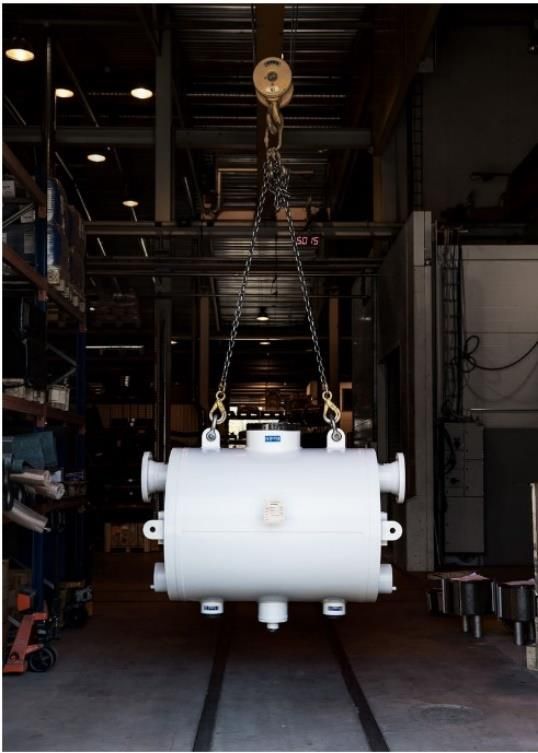
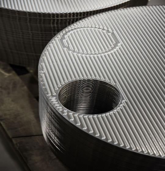
8

Pictures

Picture 1. Plate pack before final assembly. (Vahterus Oy, 2019) ........................ 11

Picture 2. One of the models in finalized state. (Vahterus Oy, 2019) .................... 11

Picture 3. Rough depiction of the line layout and machinery. ............................... 14

Picture 4. Profile picture of the important parts of a mechanical, C-type press.
(Stamtec, Inc., 2019.)............................................................................................ 16

Picture 5. Schematic of the functionality of electric motor driven presses. (Machine
design and analysis blog, 2017.)........................................................................... 17

Picture 6. Amada TP-110 during installation to its new production line................. 18

Picture 7. Crossflow valve in deactivated/resting state. (ROSS EUROPA GmbH,
2005)..................................................................................................................... 21

Picture 8. Crossflow valve normally actuated. (ROSS EUROPA GmbH, 2005.) ... 22

Picture 9. Crossflow valve in a state of malfunction. (ROSS EUROPA GmbH, 2005.)
.............................................................................................................................. 22

Picture 10. Cross section of part-revolution clutch and break with operation.
(Jabatan & Kesihatan, 2015.) ............................................................................... 23

Picture 11. The original wiring diagrams. .............................................................. 24

Picture 12. The old contactor control system within the electrical cabinet. ........... 24

Picture 13. cross section of a Eddy Current clutch and control feedback loop
explained. (Powermag Control Systems (P) Ltd., 2017.) ...................................... 25

Picture 14. Complete Rack setup with annotations. .............................................. 27

Picture 15. Unplugged Arduino and Pololu motor shield combination wired with
Bourns PSL slide potentiometer............................................................................ 28

Picture 16. Combined wiring diagram of EDC and Arduino system. ..................... 28
9

Picture 17. Main circuit diagram. ........................................................................... 30

Picture 18. Original wiring diagram for the actualization of controls. When the
program has been executed to this point, it is enabled to give the strike command.
.............................................................................................................................. 33

Picture 19. Remade actualization of controls in the PLC program. Here Midwaypoint
is an internal marker in the program for it is used by multitudes of networks. ....... 34

Picture 20. Part of the motor adjustment program from the project PLC. .............. 35

10

1 START OF THE PROJECT

This part will introduce the client and what they do. It is also explained why they
wanted this project to be done and what is expected as a result.

1.1 To whom

This work has been done for Vahterus Oy, a company focusing on manufacturing
plate and shell heat exchangers, PSHE for short, on one of their new automated
lines in the early production area that makes the innards for the heat exchangers.

Vahterus Oy is considered by Finnish standards to be a large size company, em-
ploying slightly more than 250 people worldwide and exceeding the requirement for
an annual revenue of over 40 million euros. (Directorate-General for Internal Market,
Industry, Entrepreneurship and SMEs (European Commission), 2016; Official Sta-
tistics of Finland (OSF), [Ref. 4 April 2019]) Even with their relatively small size they
have held 0.2 % of the worldwide heat exchanger market during the year 2015 and
have set the goal to supply 7 % of the PSHE market during the year 2021, with their
export taking roughly 90 % of their production. The main market of PSHE is within
oil and other chemical process, energy and refrigeration industries. (Vahterus Oy,
[Ref. 4 April 2019].)

The manufacturing, assembly and function of Plate & Shell Heat Exchangers can
be summarized with the following list:

 1. Plate material is chosen individually for every application.
 2. Plates are pressed and cut from a sheet metal.
 3. Plates are welded together to a pack, with the gaps between the plates
 functioning as channels for hot and cold circulation.
 4. Plate pack is installed in a cylindrical shell, where hot and cold circulations
 run in opposite directions on each side of the plates and each gap has
 alternately a ‘plate side’ circulation and a ‘shell side’ circulation.
 5. Circulation is directed into the pack of plates and out through combination
 pipes. (Vahterus Oy, [Ref. 15 May 2019].)
11

Picture 1. Plate pack before final assembly. (Vahterus Oy, 2019)

Picture 2. One of the models in finalized state. (Vahterus Oy, 2019)

As seen in Picture 1, the edges of the cutout holes have been TIG-welded with their
adjacent partner as will be every other outer edge of the plates. From this inner-
outer-inner style weld, a plate pack is produced which best resembles an accordion.
This pack is later installed into the shell and connected by welding the pipe connect-
ors that can be seen in Picture 2. The pipes at the ends of the shell are connected
to the inner ‘plate side’ circulation (the small hole seen in picture 1) and the pipes
on the mid-section (seen above and below) are connected to the ‘shell side’ circu-
lation which correlates to all the space between the outer shell and the plate pack.
12

1.2 Reasons

Reasoning behind the modernization decision has been long term economical gain.
The renewed line in the production, is hoped to increase energy conservation and
production efficiency. It is also expected to increase safety, simplify fault manage-
ment and shave off outdated technology.

1.3 Goals

The goal is to provide a safe, modern and efficient solution to replace the outdated
control system of the cam press. This way there would be reduced need to do
maintenance work for the press dies, which in turn should increase the quality and
quantity of manufacturing.
13

2 PRODUCTION LINE AND THE CAM PRESS

This part will be going over what the production line does and what it looks like,
before transitioning to explain the inner workings and operating principles of the
target of our modernization. (The press can be observed as the middle piece in
picture 3. and on its own in picture 6.) There is also a heavy focus on component
and function requirements within this section.

2.1 Production line

The sub sections here will be giving a rough idea about what the production line
machinery and their functions are in the manufacturing process. The safety design
is also being addressed briefly from the whole production lines perspective.

2.1.1 Basic rundown

The production line produces plates for the smaller end of the product family, and
as a line doing only relatively simple process, it has an allotted area of roughly 7
times 30 meters.

The cam press in this line is being spool fed with the chosen sheet of metal, which
it then simultaneously presses into the desired form (can be observed in Picture 1)
and cuts off the plate from the sheet, and also makes the cuts for the inner holes.
The plates are then collected and stacked by a 5-joint arm robot, before the cycle
repeats itself.
14

Picture 3. Rough depiction of the line layout and machinery.

2.1.2 Other machinery

On the line there is a spool system that consists of two parts. The first is the spool
which has the unprocessed end of the sheet metal roll and has a constant mechan-
ical brake on. The second part is the spool that uses an electrical motor to pull from
the residual processed end of the sheet metal from the first spool through a press
that straightens the sheet metal, through the gap of tool dies in the cam press and
finally onto a roll on itself. The best way to describe this would be to compare it to
an old tape recorder system that just happens to have the tape getting punchouts
at set intervals while being transferred onto the other spool.

Located between the cam press and the pulling spool there is an old ABB manufac-
tured 5-joint arm robot that serves the purpose of removing the cut out and pressed
plate from between the dies. The cam press has an in built pneumatic cylinder that
lifts the plate so it can be easily taken by the robot. Once the arm has taken a hold
of the plate, the robot will show it to an inductive sensor on the side of the cam press.
This gives permission for the rest of the line system to start a new cycle. After giving
the permission, the robot will then proceed to take the plate to the edge of production
line and stack the plate into a trolley. The trolleys will be taken to later stages of
production once filled.
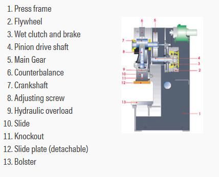
15

On the edge of the line there is fitted one welding station, within the bordering Safety
fence, that is used to make the connections of the smaller holes simultaneously with
two rotating TIG-weld pistols. This welding station can be accessed from both sides
but operated only from outside the line area. Maintenance of the station requires
access from both sides. The stations operation is completely independent from the
cycle of the line, although it was discussed if it should be a part of the line’s cycle of
automation.

2.1.3 Safety

Safe use of the production line is made possible by having the whole line closed off
by a safety fence. Only operators and maintenance personnel are permitted to enter
the fenced area, and the machinery inside can only be jogged during their stay in-
side. There are no manual work operations, concerning line functions, to be done
inside the fence either.

The production line has been designed by taking into account the European direc-
tives and standards on machine safety, and making risk assessments based on
them. The cam press’s own risk assessment will be reviewed if the solution, that is
being proposed, comes to pass.

2.2 Cam press

The cam press is by design a fast-moving machine. Thus, it differs greatly from the
usual type of press which slowly closes the dies together to produce massive and
uniform force to form the desired shape onto, or to cut away from the malleable
object. In comparison to the more traditional press, the cam press more than makes
up for the slightly higher rate of imperfect pieces in an environment that has a focus
on mass production of a simple piece. This is possible because of its high strike
rate, as it is ready to strike again as soon as the previous cycle has completed its
course.
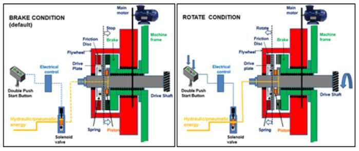
16

Picture 4. Profile picture of the important parts of a mechanical, C-type press.
(Stamtec, Inc., 2019.)

2.2.1 Amada’s functionality and limitations

Amada TP-110 is a mechanical, C-type press (called that due to the type’s outwards
appearance, that appears to resemble letters C or G), that has a maximum rating of
110 tons of force. The machinery works by having an electrical motor drive a large
flywheel, in which kinetic energy is stored and later consumed in the motion of 360-
degree cycle of the press, or shorter a stroke, to have the dies make the piece. Each
downstroke slows the flywheel roughly 10 to 15 percent, which then the motor tries
to remedy by increasing the energy on the flywheel during the upstroke in prepara-
tion of the next cycle. In the case that flywheel slowdown exceeds 15 percent in
continuous use, the motor does not have the required time to restore the lost energy
and the press will slow down too much. Resulting in a situation where after several
strokes the press will jam in the BDC. To initiate a stroke, an electric control is uti-
lized for clutch and brake, which then disengages the flywheel to the press drive.
Typical clutch and break components are spring applied, with either pneumatic or
hydraulic release. Clutch and brake stopping times have a critical role in determining
the speed the press can be run at and the safety of the operator and die. (Cattel,
2008.)
17

Picture 5. Schematic of the functionality of electric motor driven presses. (Machine
design and analysis blog, 2017.)

Flywheel driven presses have the typical use in piercing, blanking, bending and very
shallow drawing with progressive dies. With the usual tonnage being between 30
and 600 tons. As a rule of thumbs full press energy becomes available after reaching
half of the top press speed and the press stroke length is always kept as short as
possible. The SPM (strokes per minute) with this drive type is 125 to 250 on the low
end, to an excess of 1000 on the high end. (Cattel, 2008.)
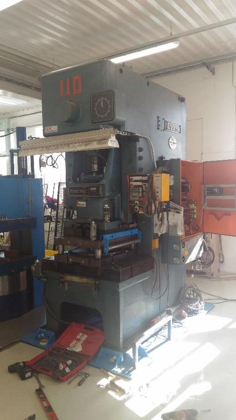
18

2.3 Original state of the machinery

Picture 6. Amada TP-110 during installation to its new production line.

In the original state of the cam press, control has been performed with a control
pedestal which has had option for both manual and automatic use. Additionally, the
cam press could have been used with a footswitch on manual operation mode.

All of the possible modular options for the press were drawn in the original electrical
schematics, but only the bare minimum was initially installed onto the press and no
modular options were retrofitted either. No alterations were made to any of the phys-
ical properties compared to the schematics. These formerly mentioned points made
the modernization process a whole lot of easier and streamlined.

2.3.1 Controlling systems and components

Original usage controls have been mostly hand operated from the control pedestal,
which houses two-hand operation pushbuttons, two pushbuttons for automatic run
mode, which have to be pressed at the same time as two-hand operation buttons
on automatic mode, a 5-position key switch for operation mode selection and an
19

emergency pushbutton. The pedestal has a 3-meter-long cable connecting it to the
electrical cabinet, giving it the possibility to be moved around the machine and work-
space.

Another way to control the press has been the use of a footswitch, which has been
used mostly if there has been a need to manually feed a sheet into the dies and to
hold it in place. To enable the use of the footswitch, a selective switch has to be
turned to a position that gives the control completely from two-hand operation to the
footswitch. In addition to the afore mentioned impediment, the footswitch can only
be used on Safety Once- and Once-modes. (Jabatan & Kesihatan, 2015.)

The press has only one key switch and it is used for changing the operating mode.
There are five positions on the switch and they correspond with Safety Once, Once,
Off, Inch and Continuous. The key for this switch should always be in the possession
of a competent or authorized personnel, such as Line-leader, Supervisor or Die-
Setter, to prevent machine abuse, with adjustments, maintenance without supervi-
sion or unacknowledged fault situations. (Jabatan & Kesihatan, 2015.)

The differences in mode selections and their usage, with prerequisites are listed
below.

 – Once: In this mode, after the stroke has been initialized, the machine will
 only do one cycle and stop after reaching T.D.C. Once is the most used
 mode in operating press machinery. (SFS-EN 692 2006, 17.)
 – Safety Once: This mode has the same principality as Once-mode, with
 the exceptions of press usage being initialized with footswitch control and
 that safety of the operator is reliant on second layer of safety features
 such as safety guards, hand tools or light curtain sensors. (The American
 Society of Mechanical Engineers, [Ref. 20 September 2019].)
 – Off: In this mode the initialization of a stroke is impossible and is as such
 the used mode for maintenance and die changing operation. Off mode
 also enables the use of following operations; Bolster movement (in and
 out), Slide adjustment (up and down) and Cushion adjustment. (Jabatan
 & Kesihatan, 2015)
20

 – Inch: The jogging mode, that is used when dies are being set or after a
 fault has occurred. The mode is intended to be used solely by die setters
 and other service personnel, as safety regulations and standards prohibit
 the usage from production operations. Slide movement in Inch-mode is
 incremental and dependent on four factors with part-revolution clutch: a)
 time of engagement of the Inch-control; b) length of the stroke; c) speed
 of the press; and d) position of the slide within the stroke. (The American
 Society of Mechanical Engineers, [Ref. 20 September 2019].)
 – Continuous: An automatic mode which repeatedly initializes a new stroke
 after the previous cycle comes to an end. To use, separate push buttons
 have to be pressed at the same time with two-hand controls and to disen-
 gage, either press the two-hand controls once more or press the stop but-
 ton on the T-stand. (SFS-EN 692 2006, 15.)

Logic/operating functions for the press are controlled with contactor control circuits.
This subject will be addressed throughout parts 2.3.2 and 3.1.

Flywheel speed control, subsequentially the press power, is done with Eddy current
system, in which the motor rotates at set speed and the rotary motion is then trans-
ferred onto the pulley by slip speed technology. This subject will be gone through in
part 2.3.3 in detail.

Half of the pneumatic system is controlled with simple 2/2 electromagnetic valves
that include Air Blow Off- and Overload-systems. The most important part of the
pneumatic system, the brake and clutch control, is controlled by SERPAR Crossflow
twin valve system. As instigated by SFS-EN 692-standard and re-enforced by Eu-
ropean directive 2006/42/EC. The both standards give similar statements that on
mechanical presses and other hazardous machines with pneumatically operated
clutches and brakes double valves at least should be used. Double valves without
self-monitoring should only be used if current regulations permit this or if the valve
is equipped with a control system, which in conjunction with the safety control sys-
tem, enables the monitoring of valve and machine. (Directive 2006/42/EC, 2006;
SFS-EN 692, 2006)
21

Picture 7. Crossflow valve in deactivated/resting state. (ROSS EUROPA GmbH,
2005)

The way Crossflow twin valve is made to be the epitome of safety with heavy ma-
chinery with pneumatic controls can be explained by taking a look at its structure.
As per the name would suggest, the twin valve has two independently actuated
valves, that are operated by solenoids, in a common housing. Within the housing
both valves have shared inlet-, outlet- and exhaust ports. During normal operation
the solenoids, that are located on the inlet side, are actuated simultaneously pulling
the valve assembly to open position and working as a regular 3/2 single valve sys-
tem. In a case where one of the valve assemblies malfunctions, either by failing to
open or close properly, the design will allow less than 2 % of the inlet pressure to
build up at the outlet port which is not sufficient for actuating the system. Instead the
pressure will be dispersed through the exhaust port. Due to the presence of the
second valve assembly, that is sometimes called redundant. The likelihood of mal-
function on both assemblies during the same cycle is considered extremely remote.
(ROSS EUROPA GmbH, 2005.)
22

Picture 8. Crossflow valve normally actuated. (ROSS EUROPA GmbH, 2005.)

Picture 9. Crossflow valve in a state of malfunction. (ROSS EUROPA GmbH,
2005.)

The clutch and brake system is of the part-revolution clutch type, which is either
pneumatically or hydraulically actuated and can be disengaged at any point of the
stroke to stop the slides motion. This is a considerably safer option and can be used
on all kinds of presses regardless of tonnage. Compared to the alternative of full-
revolution clutch type that always disengages at the T.D.C, with a mechanical re-
lease. Full revolution clutch also has only manual possibilities for early disengage-
ment. Part-revolution type clutch and brake system allows for usage modes such as
Inch to be used. Below in picture 9 is a cross section of part-revolution clutch and
break. In which can be seen the plate connected to the shaft that drives the slides
motion, being pushed by springs onto the brake elements on the left. On the right
side is shown the actuated state when the hydraulic/pneumatic pressure disengages
the break and makes contact with the flywheel. This causes power to be transferred
into the slide. Plainest explanation for part-revolution clutch and brake would be that
it is a reverse-function car transmission. (Jabatan & Kesihatan, 2015.)
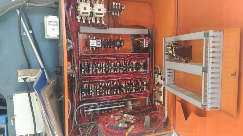
23

Picture 10. Cross section of part-revolution clutch and break with operation. (Jab-
atan & Kesihatan, 2015.)

The feedback of the state of cycle comes from mechanical lever switches, will be
referred as LS from this point onwards, that monitor cams attached to a rotating rod
connected to crank shaft. This type of measurement of slide position, based on the
angular position of the crank throw in comparison to the common reference point of
T.D.C is called Crank angle. (The American Society of Mechanical Engineers, [Ref.
20 September 2019].)

2.3.2 Electrical systems

The machinery holds three different AC-voltage ranges, with three transformers and
several phase amounts. 380 V 3-phase mains for the motor, 200 V 3-phase for lu-
brication systems and 1-phase for eddy current motors control board, 100 V single-
phase for contactor operations.

As the machine was built 1959, its electrical control system has been ever since the
now outdated contactor system which at the time was prevalent. The amount of
contactors utilized by this old system has been two main contactors and 25 process
control contactors.
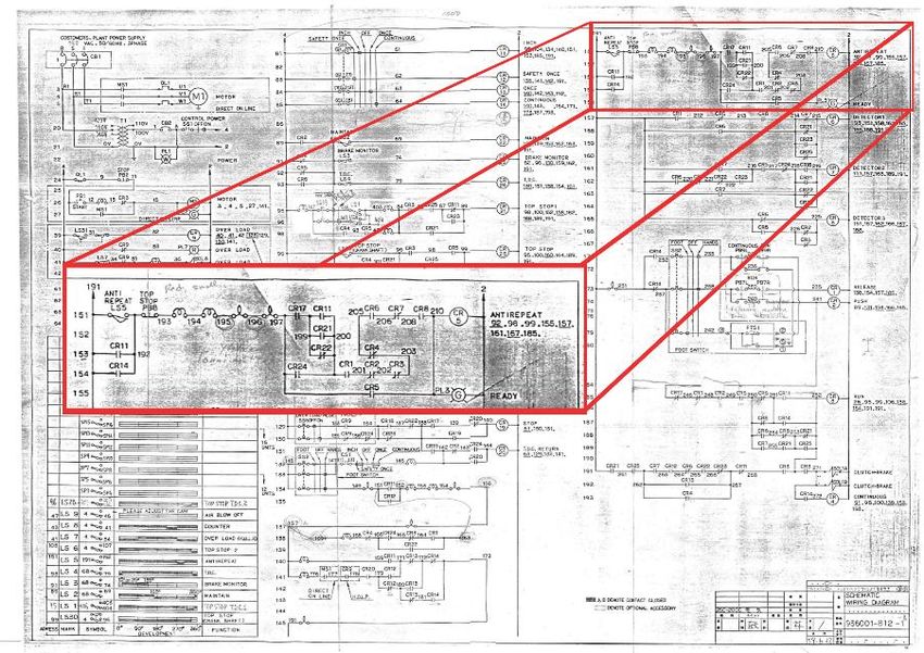
24

Picture 11. The original wiring diagrams.

Picture 12. The old contactor control system within the electrical cabinet.

2.3.3 Eddy Current system and the drive motor

Motor in an Eddy Current-system is an induction type motor, meaning it is actuated
by AC-power. (Chapman 2005, 230). In more detail the motor in the system is de-
sign class D. Typical characteristics for class D motors are very high starting torque
25

and low starting current, but at a cost of having high slip at full load. This is achieved
by having the rotor bars made smaller and from higher resistance material com-
pared to type A motors, The high rotor resistance causes peak torque to shift to a
very low speed, as well as full-load slip to increase up to 17 percent or more from
the typical 7 to 11 percent. These characteristics make type D motors ideal for ap-
plications requiring the acceleration of extremely high-inertia-type loads, especially
large flywheels used in punch presses or shears. (Chapman 2005, 416–423.)

Picture 13. cross section of a Eddy Current clutch and control feedback loop ex-
plained. (Powermag Control Systems (P) Ltd., 2017.)

The Eddy Current system works by having an AC-motor that was detailed in previ-
ous paragraph rotate at its nominal speed, that is defined by rotor slip (see Terms
and Abbreviations), turning the drum part of Eddy Current clutch. Drum has excita-
tion windings that are supplied with a DC-current from Eddy Current Drive/Field Ex-
citer and Controller (EDC). This current with the rotary motion of the drum, cause a
magnetic attraction to occur between the drum and inductor coils on the output shaft.
With a higher current more power in terms of speed and torque will be transferred
into output shaft. The way the amount of current is controlled in excitation windings
is done by giving the drive/controller unit an analogue value (in this case with a 10k
ohm potentiometer) that is then compared to a feedback value generated by a ta-
chometer generator at the output shaft. Terminology for this control can be either
Degree of coupling or Slip speed. (The-Crankshaft Publishing, [Ref. 29. September
2019].)
26

3 PLANNED STATE OF THE MACHINERY

This is the part which will be going through what kind of changes are being proposed
for the project with their reasoning behind them and impact on the machinery. All of
the new components that are being implemented into the project are also being
introduced and explained.

3.1 Planned changes into control scheme and operations

The control for normal usage in production will be given to Siemens ET200S PLC,
which would be installed in the old electrical cabinet and function as a slave PLC to
the production lines master PLC. The PLC program that has been created for this
solution, has been made by having the original electrical schematics as the founda-
tion for the core function in the program and then expanding upon that core neces-
sary and wanted additions were made.

In the end the program has come to utilize following amounts and types of I/O; five
fail-safe digital inputs, 31 digital inputs out of which one comes from master PLC,
four fail-safe outputs, eight digital outputs out of which three are sent to master PLC,
one analogue output and a Profinet connection between PLC and HMI. These con-
nections amount to five digital input-, two digital output-, one analogue output-, one
digital f-input- and one f-output-modules on the PLC rack (see picture 14 for refer-
ence).

In addition to previous paragraphs listing, the project has following types of hard-
ware which are not connected to the rack. HMI (Siemens KTP700 Basic PN) and
Arduino UNO board connected with Pololu Dual Motor Driver Shield board, that are
used to adjust Eddy Current systems control board EDC.
27

Picture 14. Complete Rack setup with annotations.

As this solution won’t be replacing the old Eddy Current system but removes the
potentiometer that was used to adjust the slip speed of the clutch, there became a
need to have a replacement control system for EDC. Considering EDC is powered
and functions with 200 VAC, the choices became limited from the start, for PLC’s
normal operating voltage is 24 VDC and analogue output voltage measly 10 VDC
(Siemens AG, 2007). Meaning the utilization of motorized rheostat was mandatory.
Even though the PLC would have been more than capable of doing the adjustment
of rheostat (Bourns PSL Slide Potentiometer was chosen for this project). It was
decided that Arduino board would be set as a slave for this task. To protect the PLC
and it’s modules to an extent from possible malfunctions and lessen the burden of
computing for the PLC.
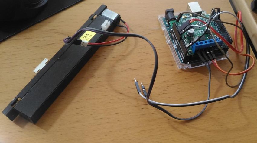
28

Picture 15. Unplugged Arduino and Pololu motor shield combination wired with
Bourns PSL slide potentiometer.

Picture 16. Combined wiring diagram of EDC and Arduino system.

Arduino boards addition to the project brought up the need for an electrical socket
with a plug-in 230 VAC to 12 VDC power adapter to be installed inside the electrical
cabinet (seen in picture 16). This was required as Arduino’s operating voltage is 7-
12 VDC. Arduino’s I/O system also required special attention on communication with
PLC, as the I/O systems rated voltage range is 5 VDC. The latter was remedied by
limiting the value PLC’s AO-module receives internally to match Arduino’s ADC sys-
tem. (Arduino AG, [Ref. 2. October 2019].)
29

Control pedestal and footswitch would still be left for manual control for maintenance
and the possible fault situations. Although, the pedestal would still be renewed with
a one that doesn’t have the possibility to use automatic mode, meaning the absence
of auto-push buttons on the sides. Even though it could be said to be only a cosmetic
change, for the usage is blocked within the plc program. Footswitch’s functionality
will be converted from strike permission into electromagnetic pneumatic valve con-
trol. That then operates the pneumatic cylinder for lifting the pressed and cut out
plate in between the dies.

There will also be change with the key switch system. This solution proposes that
the system will be made to be two stage process. Which means the number of key
switches will be doubled, the first one staying at its previous location at the control
pedestal and the new addition would be placed on the cover of electrical cabinet in
the vicinity of HMI. Both will retain the original five mode choices (Safety Once, Inch,
Off, Once, Continuous), and will have to be in unison with each other in order to give
usage permission. The permission is always rescinded if either switch has been
operated and will have to be acknowledged from HMI.

As the operating voltage for process control has been reduced and changed type
into 24 VDC, there also has to happen renewal on the instrumental side. Such as
the electromagnetic valves, that are part of the pneumatic system and control clutch
and brake functions.

The LS system will stay as is, with the only modification being that it will be rewired
into the PLC. LS’s are still the preferred method of feedback as it is mechanical, with
little to none wear, meaning the tolerance within measurement is extremely low.
Changes within mechanical measurement such as this should only be possible if
the machine is for one reason or another dis- and reassembled. (Bairwa, 2018.)

3.2 Renewed electrical systems

To modernize the electrical system, some visually drastic changes will happen. As
the solution has thus far given out, the greatest change will happen in the form of
process controlling equipment which will leave the electrical cabinet looking rather
30

sizeable for the required instrumentals. For considering you will only be needing the
space of roughly four to five contactors with the wanted PLC and its modules, as the
primary process control equipment. Then the space required for Arduino-Rheostat
control can be added to this, which equates to a rough estimate of one contactor,
and lastly, also taking two contactors worth of space, the 3-phase 400 VAC to 24
VDC transformer to power the new PLC and its affiliates. So all in all the new system
by this solution would be taking roughly the space of eight contactors, and by com-
paring that to the current system. Where the number of contactors is 25, there will
be a decrease of 13 in required space in the electrical cabinet.

There will be only one contactor assembly (Siemens SIRIUS 3RA2) left in the elec-
trical cabinet within this solution and those are the new main contactors, that control
the usage of the motor in the Eddy Current system. Even while this solution leaves
the contactors in, they will still be renewed as both a precautionary method, for they
are possibly multiple decades old, and the system needs contactors that can be
actuated with 24 VDC.

Picture 17. Main circuit diagram.
31

3.3 Reasoning for drive system retainment

As stated in 3.1, this solution will not be changing the old Eddy Current motor for a
newer one. There were few things to consider whilst making this decision and the
one that was found to be the one with most impact was how the Eddy Current han-
dles within emergency situations. As per Eddy Current’s style of operation no addi-
tive energy will be transferred in the system and no strain will be caused onto the
driving motor as the flywheel is physically separated from the motor. (Refer to 2.3.3.
and picture 13.)

There is also no real need to change the Eddy Current system as it has shaft bear-
ings and drive belts as the only parts that experiences real wear in the system. And
if the decision to renew the system would be made, the EDC, Eddy Current clutch
and the motor would all have to be changed together. In which case there would
have to be consideration on the subject of “Does the Eddy Currents better safety
behavior and rare need of maintenance outweigh its energy inefficiency compared
to a system where you would use a VFD-controlled motor?”. In the European region
industries have opted for the latter method of control, whereas North American in-
dustry still has the preference on having Eddy Current systems as the drive. As can
be understood from the disagreeing Dynamatic and their shared insight upon the
matter. (Dynamatic Drive Source International Inc., 2019.)

3.4 Current state of the machinery

Currently before any of the proposed modifications have been made, the control of
the usage of the cam press in the production line has been given to the master PLC
situated on the line and as such been controlled with the original contactor control
circuits.
32

4 MODERNIZATION OF CONTROL SYSTEM AND
 DOCUMENTATION

This part will focus on describing what has been done during the course of the pro-
ject. Attention is paid to the planning process and the phases it incorporated.

4.1 Hardware check-up

The first phase of the project was hardware check-up, where the components of the
machinery were checked by the frequency and functioning of their use as well as
their necessity for operation. With this information the preliminary choices between
removal or replacement were made. The finalized decisions were made in phase
three which is discussed in 4.3. At that point there was a complete logic program
and a full picture of the needed components.

The framework that was given for the decisions by the client was that the contactor
control circuits were to be removed and replaced by PLC-control and that the old
control interface would be replaced. Otherwise, free reign was given over the
choices concerning the component decisions in the project. Such decisions were
renewal of the T-stand, operation of the footswitch and retainment of the Eddy Cur-
rent system.

This was the phase where the necessity of the Eddy Current system was thought
through, before the programming phase. Even though the program was made to be
easily modified if it was required to be alternated to work with the second option for
the motor control (VFD).

4.2 Program building and planning

The second phase of the project was about building a logic program based on the
framework established in phase one, doing research on the requirements for the
project and starting electrical planning to accompany the mechanical planning made
in phase one.
33

The programming tool/environment for this project has been Siemens’ own TIA-Por-
tal version V15.1, in which the program was compiled in ladder type of programming,
using the original wiring diagrams as a base. After this the program was edited to
establish the required expanded features. These features were taken from stand-
ards such as SFS-EN ISO 14 121-1 and -2, that handle aspects of machine safety.

Standards regarding the project were an integral part for the project as they define
the minimal component features, safety values and parts of programming that have
to be present. After the afore mentioned were acquired, the programming was
started from transcribing.

The main framework of the program was made almost purely by copying the old
control circuits from the diagrams and converting them into ladder format, as can be
perceived in pictures 18 and 19 after this paragraph and within appendix 1. Most of
the additive function blocks in the program were ones that handled safety functions
in one way or another and the rest of the bulk were ones handling the communica-
tion between the PLC and HMI. Motor adjustment function block was one of such,
as it took the inputs from the HMI returning a percentile value back and guiding
motor slip control through the analogue module to Arduino, rheostat and EDC.

Picture 18. Original wiring diagram for the actualization of controls. When the pro-
gram has been executed to this point, it is enabled to give the strike command.
34

Picture 19. Remade actualization of controls in the PLC program. Here Mid-
waypoint is an internal marker in the program for it is used by multitudes of net-
works.

HMI was one of the features requested by the client to be added into the moderni-
zation project to ease the usage and moderation of line functions. The placement of
the HMI was discussed to be either on the face of the box that houses the current
analogue controls or on the door of the electrical cabinet, depending on if there is
sufficient surface area on the face of the box and enough space inside it. The main
interface can be observed in the appendices.

Arduino UNO board’s programming, to work as the middle piece in motor slip con-
trol, was done with Arduino’s own open software program called Arduino IDE. All
this material can be found at Arduino’s web page on the resources tab. The rheostat
control was one aspect in the project that could be pre-adjusted to be correct by
making a mock program on an available PLC and running test sets with it. Which
was considered as essential as there seemed to be a lot of noise from the wiring,
and the absence of positional feedback from the motor forced us to rely on a rough
mathematical value for actuation time to be adjusted. Consequently, the mock pro-
gram and its values were integrated into the project program as they had already
been tuned to acceptable limits. Below in picture 20 can be seen part of the motor
control program from the project PLC, that is adjusted via HMI.
35

Picture 20. Part of the motor adjustment program from the project PLC.

The program is currently only a proposed solution, that will be gone through with the
client and then finalized during installation and deployment of the new control equip-
ment. The program and machinery will have to be adjusted to get them to work with
each other and as a part of the production line as intended. Even though all the
aspects have been thought over a multitude of times there is always something to
be adjusted.

4.3 Electrical diagrams and finalizing component choices

The third phase covers redrawing electrical diagrams and finalizing component
choices within electrical- and mechanical planning that were started in phases one
and two of the project. Although, the new component choices were by the most part
already selected by the redrawing, all that there was left to be done was to put them
in.

Electrical planning and drawing was done with CADS Electric Pro program. In the
new diagrams only the originally installed modular options were redrawn and PLC
to field I/O -connections were added in place of the old contactor control circuits.
36

During the redrawing process all old components were checked for either replace-
ments or upgrades. This was made possible by having a table of all the program I/O
-connections and the necessary components to make the planned control schema
work as intended.

In the appendices it is possible to observe additional extracts from the diagrams.
The diagram of the oil pump needed the most modifying compared to other original
components, as it needed additional relay control to be able to communicate with
the PLC.
37

5 SUMMARY

Overall the project was quite an interesting piece of work as it had to incorporate so
many aspects together. Such as, how the line and machine worked, the thought
process of deciding the components and evaluating the machine drives and their
control schemes.

A big part of the project was the safety-oriented planning, as we were working on
large mechanical machinery that poses a great risk of injury (typically leading to
severe damage- or death of the operator). The safety standards that impose the
requirements and levels of operation were strictly considered when considering the
parts and the control mechanics.

With the knowledge of safety requirements, it became clear what needed additional
attention in the actual process of modernizing the control while building the PLC
program and what had to be considered later on in the component choices when
drawing the electrical diagrams. The programming phase was straightforward due
to it mostly being transcribing the old wiring diagram into a ladder format, but had
its progress slowed by Eddy Current control planning that introduced the Arduino
board into the project as a medium for PLC and EDC. The process of redrawing the
diagrams was best done after having completed most of the programming phase.

Only a fraction of the actual work has been showcased in this thesis. All the docu-
mentation and programs will be handed over to the client after the set-up of the new
system is complete. There may occur some slight changes to either during the set-
up phase, as the program will need to be adjusted to be precise.

Prior to the handover of the project it can be declared that the goals set at the start
have been partially met. The safety functions have been heightened in addition to
the safety modules to PLC and having the manual controls only to be used in special
occasions, as normal operation is done on other side of the safety fence surrounding
the production line. Production efficiency and fault management both have become
better with the modern equipment that is faster and capable of communicating with
the rest of the production line and with operator via HMI. Energy conservation is
arguably better than with the alternate drive option, but the controlling functions are
38

more efficient in the matter than the current system. The drive source and lubrication
pump were not updated in this proposition, but options for replacement will be given
at the hand over to the client (see Dynamatic Drive Source International Inc., 2019).
39

BIBLIOGRAPHY

Adjustable-speed systems (Electric Motor). [Web page]. The-Crankshaft Publish-
 ing. [Ref. 29. September 2019]. Available at: http://what-when-how.com/elec-
 tric-motors/adjustable-speed-systems-electric-motor/

Arduino UNO Rev3. [Web page]. Arduino AG. [Ref. 2. October 2019]. Available at:
 https://store.arduino.cc/arduino-uno-rev3

Bairwa, M. 2018. [Web page]. Types of cams and followers. [Ref. 7. October
 2019]. Available at: https://www.mech4study.com/2018/08/types-of-cams-and-
 followers.html

Cattel, D. 2008. Stamping 101: Anatomy of a Mechanical Press. Stamping Journal
 January/February 2008. [e-publication]. Elgin: FMA Communications, Inc. [Ref.
 30 August 2019]. Available at: https://www.thefabricator.com/article/stamp-
 ing/stamping-101-anatomy-of-a-mechanical-press

Chapman, S.J. 2005. Electric machinery fundamentals. 4th ed. New York:
 McGraw-Hill.

Directive 2006/42/EC of the European Parliament and of the Council on machin-
 ery.

Directorate-General for Internal Market, Industry, Entrepreneurship and SMEs (Eu-
 ropean Commission). User guide to the SME definition. 2016. [e-publication].
 ISBN=978-92-79-45301-4. Luxembourg: Publications Office of the European
 Union. [Ref. 4 April 2019]. Available at: https://publications.europa.eu/en/publi-
 cation-detail/-/publication/79c0ce87-f4dc-11e6-8a35-01aa75ed71a1

Dynamatic® versus VFD. 2019. [Web page]. Sturtevant: Dynamatic Drive Source
 International, Inc. [Ref. 15 October 2019]. Available at: https://www.dyna-
 matic.com/dynamatic-technology/dynamatic-versus-vfd/

Eddy Current Variable Speed Drives. 2017. [Web page]. Powermag Control Sys-
 tems (P) Ltd. [Ref. 26 September 2019]. Available at:
 http://www.powermag.in/eddy-current-variable-speed-drives/

Glossary of Power Press Terms. [e-publication]. The American Society of Mechan-
 ical Engineers. [Ref. 20 September 2019]. Available at:
 https://cstools.asme.org/csconnect/Filedown-
 load.cfm?43452.5201505&dir=CommitteeFiles&thisfile=26833.pdf

Jabatan, K. & Kesihatan, P. 2015. Guidelines On Safe Use Of Press Machines. [e-
 publication]. ISBN=978-983-2014-80-5. Putrajaya: Department of Occupational
 Safety and Health. [Ref. 19. September 2019]. Available at:
40

 http://www.dosh.gov.my/index.php/en/legislation/guidelines/industrial-
 safety/1847-01-guidelines-on-safe-use-of-press-machines-2015/file

Official Statistics of Finland (OSF): Small and medium size enterprises. [e-publica-
 tion]. Helsinki: Statistics Finland. [Ref. 4 April 2019]. Available at:
 http://www.stat.fi/meta/kas/pienet_ja_keski_en.html

Power press design calculation. 2017. [Web page] Machine design and analysis
 blog. [Ref. 16 September 2019]. Available at: https://mechextreme.blog-
 spot.com/p/manufacturing.html

ROSS EUROPA GmbH. 2005. Bulletin E380B: SERPAR® Crossflow Double
 Valves with Pressure Switches. [e-publication]. Langen: ROSS EUROPA
 GmbH. [Ref. 23 August 2019]. Available at: https://www.rosseuropa.com/filead-
 min/redaktion/en/documentation/catalogs-booklets/pdf/E380B.pdf

SFS-EN 692. 2006. Machine tools – Mechanical presses – Safety. Helsinki: Finn-
 ish Standards Association.

Siemens AG. 2007. Manual A5E01076916-01: 2AO U ST analog electronic mod-
 ule (6ES7135-4FB01-0AB0). Nürnberg: Siemens AG.

Stamtec Inc. 2019. OCP Series Gap Frame Press. [Web page]. Stamtec Inc. [Ref.
 19 September 2019]. Available at: https://www.stamtec.com/ocp-series-gap-
 frame-press#press-components

Vahterus Oy. Applications. [Web page]. Kalanti: Vahterus Oy. [Ref. 15 May 2019].
 Available at: https://vahterus.com/applications

Vahterus Oy. Company. [Web page]. Kalanti: Vahterus Oy. [Ref. 4 April 2019].
 Available at: https://vahterus.com/company/careers
41

APPENDICES

APPENDIX 1. Example from conversion of process controls

APPENDIX 2. Main interface on HMI

APPENDIX 3. Extracts from electrical diagrams
1(1)

APPENDIX 1. Example from conversion of process controls

The old antirepeat contactor control circuit highlighted above and the new ladder structure in the program shown below.
1(1)

APPENDIX 2. Main interface on HMI

The main interface for HMI, with a brief operation instruction included.
1(2)

APPENDIX 3. Extracts from electrical diagrams

Diagram of base power module with the depicted digital input modules, that are supplied by it.
2(2)

Oil pumps updated electrical diagram.
You can also read