MORABA Mobile Launch and Range Infrastructure
←
→
Page content transcription
If your browser does not render page correctly, please read the page content below

Space Operations and Astronaut Training
Portfolio: MORABA

          MORABA
          Mobile Launch and Range Infrastructure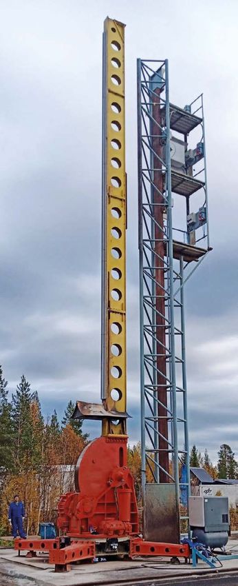

Space Operations and Astronaut Training
Portfolio: MORABA

                                                                                              1.   MORABA Mobile Launc
                                                                                              and Range Infrastructure

                                                                                              Title and all Photos: © Credit: DLR CC BY-SA 3.0 IGO

MORABA Mobile Launch and Range Infrastructure
The Mobile Rocket Base (MORABA) at DLR Space Operations carries out sounding rocket and balloon missions for scientific research.
It provides efficient and unique research possibilities in the fields of atmospheric physics, microgravity, hypersonic research, tech-
nology testing and education. MORABA integrates all necessary key technologies like electronics, radio, flight dynamics and mechanics
in one department. This experience and competence is valued and sought after by national and international facilities, industry and
institutions of higher education.

MORABA has developed a unique mobile infrastructure and hardware for the planning, preparation and implementation of sounding
rocket projects. In principle, it can be used to launch a rocket from anywhere on Earth within a short space of time.

A detailed overview of MORABA‘s Mobile Telemetry Station, Mobile Range Instrumentation Radar and the MAN 2 Mobile Launcher
is presented hereinafter.

     More information about                                                       Highlights
MORABA services can be found                                                      •   High mobility, flexibility and adaptability
     in the Portfolio Module                                                      •   Worldwide operation
  „MORABA Sounding Rocket                                                         •   Minimal requirements on site
                                                                                  •   Operation in extreme environmental conditions
         Flight Experiments“.                                                     •   Reliable tracking of highly dynamic vehicles

Point of Contact

German Aerospace Center (DLR)
Mobile Rocket Base
Münchener Str. 20, 82234 Weßling

Telemetry Station:
Andreas Kimpe, Phone: +49 (0) 8153 28 2780 / E-Mail: Andreas.Kimpe@dlr.de
Radar Station:
Dietmar Kail, Phone / +49 (0) 8153 28 2600 / E-Mail: Dietmar.Kail@dlr.de
MAN 2 Launcher:
Frank Scheuerpflug, Phone +49 (0) 8153 28 3649 / E-Mail: Frank.Scheuerpflug@dlr.de

DLR.de/RB

2021-03-25_RB_SP_MORABA_Mobile                                                                                                         Page 1
Launch and Range Infrastructure_v01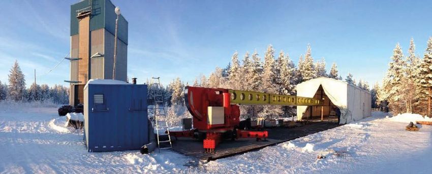
Space Operations and Astronaut Training
                                                                                                      Portfolio: MORABA

         Table of Contents

         1.	MORABA Mobile Launch and
             Range Infrastructure. . . . . . . . . . . . . . . . . . . . . . . . . . . . 1

         2.       Mobile Telemetry Station
         2.1      Principal constituents . . . . . . . . . . . . . . . . . . . . . . . . . . . . . . . . . . . . .  3
         2.2      Main Features . . . . . . . . . . . . . . . . . . . . . . . . . . . . . . . . . . . . . . . . . .  4
         2.3      Field of operation  . . . . . . . . . . . . . . . . . . . . . . . . . . . . . . . . . . . . . . .  4

         3.       Mobile Range Instrumentation Radar
         3.1      Tracking Radar RIR-774C  . . . . . . . . . . . . . . . . . . . . . . . . . . . . . . . . . .  7
         3.2      General Characteristics Tracking Radar RIR-774C  . . . . . . . . . . . . . . .  8

         4.       MAN 2 Mobile Launcher
         4.1      General characteristics  . . . . . . . . . . . . . . . . . . . . . . . . . . . . . . . . . .  12
         4.2      Electrical Specification . . . . . . . . . . . . . . . . . . . . . . . . . . . . . . . . . . .  12
         4.3      Transportation . . . . . . . . . . . . . . . . . . . . . . . . . . . . . . . . . . . . . . . . .  13
         4.4      Current positioning . . . . . . . . . . . . . . . . . . . . . . . . . . . . . . . . . . . . .  13

         Publisher
         German Aerospace Center (DLR)
         Spacecraft Operations and Astronaut Training
         Münchener Straße 20, 82234 Weßling

         Photos
         @ DLR CC-BY-3.0

Page 2                                                                               2021-02-17_RB_SP_MORABA_Mobile
                                                                                      Launch and Range Infrastructure_v01
Space Operations and Astronaut Training
Portfolio: MORABA
2. Mobile Telemetry Station
MORABA maintains and operates a mobile telemetry, tracking and telecommand station in the S-band fre-
quency spectrum. The station is composed of CSC standard ISO containers and as such can be set up around
the globe with minimal requirements on the site. The 1.5m Secondary Antenna can be stored in boxes and
used as aiding antenna together with the 5m Primary Antenna or as independent highly flexible receiving
station. The Antenna Pedestals are designed for high angular velocities and accelerations to maintain a
reliable tracking even for highly dynamic vehicles. The control station is equipped to simultaneously receive,
record and support several Telemetry and TV streams with various modulation schemes. It is self-contained
and adaptable to a variety of configurations.
2.1 Principal constituents
Control Station
• Two side expandable, isolated 20‘ ISO-Container
• Redundant external power supply with automatic selection
• Internal UPS for ~30 min
• Dual air condition for equipment and operating room for outdoor tem-
peratures from -40°C to +50°C
• Telemetry instruments mounted in five vibration damped 19’’ Racks
–– AL-4000 Orbit Antenna Control Unit
–– 6 Cortex RTR Dual Receiver
–– 4 Intus TV Dual Receiver
–– 2 Wideband digital Recorder
–– Spectrum Analyzer, Oscilloscopes
• Separated office and workshop area
Primary Antenna
• 5m parabolic reflector, segment able
• Main Feed:
–– S-Band 5 Element E-Scan Tracking Feed
–– RHC/LHC simultan
–– S-Band Uplink
• Acquisition Feed:
–– S-Band 4 Element SCM Tracking Feed
–– RHC/LHC simultaneous
• Orbit AL-4034D Pedestal, EL over AZ, Dual drive
• Verification camera
• Operable on ISO-Flat Rack
• Transportable on ISO-Flat rack with cover
Secondary Antenna
• 1,5m parabolic reflector
• Feed:
–– S-Band 5 Element E-Scan Tracking Feed
–– RHC/LHC simultaneous
• Orbit AL-4012S Pedestal, EL over AZ
• Verification camera
• Independent or cooperative operation possible
• Transportable in boxes
• Possiblity to use custom feeds for example:
–– UHF TX
–– C-Band RX
–– X-Band RX
2021-03-25_RB_SP_MORABA_Mobile Page 3
Launch and Range Infrastructure_v01
Space Operations and Astronaut Training
                                                                                                    Portfolio: MORABA

         Fig. 2-1    Mobile Telemetry Station at Esrange Space Center, Sweden

         2.2           Main Features
         • High mobility, easy transportation of the standardized ISO
           Container via Truck, Train or Ship
         • Low requirements on Site infrastructure
         • Easy installation of the station with few personnel
         • Designed for adverse environmental conditions, like extreme
           temperatures in arctic or tropic regions, strong winds, saline
           air in coastal areas
         • Flexibility and adaptability

         2.3           Field of operation
         •   Sounding rockets and balloons
         •   Supersonic and re-entry missions
         •   Airplane and Drone test
         •   Satellite missions, First acquisition

Page 4                                                                            2021-03-25_RB_SP_MORABA_Mobile
                                                                                   Launch and Range Infrastructure_v01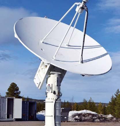
Space Operations and Astronaut Training
Portfolio: MORABA

                      Station Specifications
                      Power Supply               Mains                        3 Phase 400V or 200V 63A
                                                 Backup                       3 Phase 400V 63A IT-Net
                      Power Redundancy           Automatic switching between Mains/Backup
                                                 UPS for switching and ~30min autonomous operation
                      Air Condition              2 separate A/C circuits for rack equipment and personnel
                      Antenna Control Units      2 Orbit AL-4000 ACUs
                      Receiving Equipment        6 Cortex RTR dual channel TM receivers
                                                 4 Intus dual channel TV receivers
                      Recording                  2 Wideband DRS3000

                      Main Antenna Specifications
                      Pedestal Motion Type       Elevation over azimuth
                      Drive Type                 Dual servo drives
                      Movement Range             Azimuth                      unlimited
                                                 Elevation                    -3° to 183°
                      Max. Velocity              25°/s
                      Max. Acceleration          25°/s²
                      Pointing Accuracy          < 0.05°
                      Tracking Accuracy          < 0.5°
                      Tracking Velocity          25°/s (stable tracking)
                      Dish Diameter              5m parabolic
                      3 dB Beam width            1.8°
                      Gain                       38 dBi                       @ 2.3 GHz
                      Feed Type                  Main                         5 element prime focus
                                                 Acquisition                  4 cavity backed elements
                      Tracking Type              Main                         E-Scan
                                                 Acquisition                  Single Channel Monopulse
                      Scan Rate                  500 Hz
                      Receive Characteristics    Polarity                     LHCP and RHCP simultaneously
                                                 Frequency Range              S-band: 2200 - 2400 MHz
                                                                              System is prepared for optional upgrade to C-band
                                                 G/T                          > 14 dB
                                                 Dynamic Range                96 dB
                                                 Response                     ripples over whole frequency range < 2 dB/K
                      Transmit Characteristics   Polarity                     LHCP or RHCP, simultaneous with reception
                                                 Frequency Range              S-band: 2000 - 2100 MHz
                                                 Output Power                 2 redundant 100 W power amplifier
                                                 Max. EIRP                    52 dBW

                      Environmental Specifications
                      Temperature:               -40°C to +50°C operational
                      Wind:                      80 km/h operational
                                                 180 km/h stowed
                      Precipitation:             Rain, Snow, Icing

2021-03-25_RB_SP_MORABA_Mobile                                                                                                    Page 5
Launch and Range Infrastructure_v01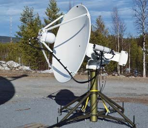
Space Operations and Astronaut Training
                                                                                                             Portfolio: MORABA

          Site Requirements
          Power Supply            3 Phase 400V or 200V, 63A, IEC 60309 3L+N+PE
                                  Either via mains supply or electric generator (400V)
          Required space:         Control Station:            min. 8m x 8m, flat area
                                  Main Antenna:               min. 8m x 4m, flat area, undistorted view to mission area
                                                              Maximum distance to Control Station 20m to 30m
                                                              (depending on orientation)
                                  Secondary Ant:              min. 4m x 4m, flat area, undistorted view to mission area
                                                              Maximum distance to Control Station 20m to 30m
                                                              (depending on orientation)
                                  Antenna Cover:              min. 8m x 4m, flat area to place Antenna cover
                                  Transport Container:        min. 8m x 4m, flat area
          Required Ground:        Asphalt, concrete or solid gravel
          Main Antenna:           Concrete or stripe foundation with fixing points required, if wind loads >80 km/h possible

          Secondary Antenna Specifications
          Pedestal Motion Type:   Elevation over azimuth
          Max. Velocity:          30°/s
          Max. Acceleration:      30°/s²
          Tracking Velocity:      30°/s (stable tracking)
          Dish Diameter:          1.5m parabolic
          3 dB Beam width:        5°
          Gain:                   28 dBi @ 2,3 GHz
          Feed Type:              5 element prime focus
          Tracking Type:          E-Scan
          Scan Rate:              500 Hz
          Receive Polarity:       LHCP and RHCP simultaneously
          Frequency Range:        S-band: 2200 - 2400 MHz
          G/T:                    3 dB

         Truck and lifting device accessibility required to place Control Station Container (10t),
         Antenna Flat Rack Container (10t) and for installation of the Antenna.

         Communications (Internet, Ethernet, Telephone, Intercom …) required depending on Mission configuration.

Page 6                                                                                      2021-03-25_RB_SP_MORABA_Mobile
                                                                                             Launch and Range Infrastructure_v01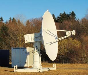
Space Operations and Astronaut Training
Portfolio: MORABA
3. Mobile Range Instrumentation Radar
3.1 Tracking Radar RIR-774C
DLR-MORABA’s tracking radar RIR-774C is a highly mobile and highly accurate C-Band (5.4-5.9 GHz), Mono-
pulse, single target tracking radar.
The station is composed of 4 CSC standard ISO containers and as such can be set up around the globe with
minimal requirements on the site. The 8 foot Antenna can be stored inside the Pedestal-Container for trans-
port. The Antenna-Pedestal-System is designed for high angular velocities and accelerations to maintain a re-
liable tracking even for highly dynamic vehicles. The Radar can track in Skin- (passive reflection) or Be-
acon-Mode (actice transponder on-board).
A solid ground platform is needed for the containers (5 to 13 tons of weight).
The internal analog intercom system (4-wire) for communication can be adapted to other intercom systems.
To synchronize the time code generator a external IRIG-B signal or the internal GPS clock can be used.
Tracking data will be recorded on the radar computer internal (hard disk) or external (USB device) in 100 Hz.
Online tracking data (target position data only in 10 Hz) and the antenna camera video can be sent externally
by an Ethernet link.
Further technical specifications of the radar, such as pedestal, antenna, transmitter, receiver, optics, etc., are
listed in the attached spec-sheets from the manufacturer of the radar.
Fig. 3-1 Impressions of the Mobile Tracking Radar at Andøya Space Center, Norway.
2021-03-25_RB_SP_MORABA_Mobile Page 7
Launch and Range Infrastructure_v01
Space Operations and Astronaut Training
                                                                                                                     Portfolio: MORABA

3.2          General Characteristics Tracking Radar RIR-774C
 Characteristic                            Specification
 Type                                      RIR-774C, Transportable C-Band Radar
 Tracking Accuracy                         0.015° (0.247 Mils) RMS with 10 dB SNR, Angles
                                           +/- 5 meters RMS with 10 dB SNR, Range
 Data Precision                            19-bit, angle
                                           32-bit, range
 Digital Data Output                       RS232
 Operating Modes                           TV and RF (skin, beacon, mixed, designate)
 Acquisition Aids                          Range-Hit Processor (Auto Acquisition for full PRT or 3k yard segment)
                                           Angles-Local Designate (Optical Director), Computer GEN. scans
                                           Angles and Range-Remote Designate (via data link)
 Shelter
 a) Type                                   4 each standard ISO containers (CFE)
 b) Dimensions (LxWxH)                     20’ (3 exandable to 28’) X 8’ X 8’6”
 c) Designations                           1 ea Pedestal Cont., 1 ea Electronics Cont., 1 ea Lab Cont. and 1 ea Transport Cont.
 Weight
 a) Pedestal Container                     Approximately 13 tons
 b) Electronic Container                   Approximately 9 tons
 c) Lab Container                          Approximately 7 tons
 d) Transport Container                    Approximately 5 tons
 Calibration Equipment                     a) TV/Optics (STARCAL Program)
                                           b) Precision Level Meter

Table 3-1 Overall System Characteristics

 Characteristic                            Specification
 Input Voltage, Pedestal Container         220/380 V AC, +/- 10% of nominal, WYE 3-phase, 4-wire, 50 Hz +/- 3 Hz
 Transmitter Output Power (Peak)           650 kW measured at magnetron output flange
 Transmitter Output Power (Average)        650 W measured at magnetron output flange
 Transmitter Output Frequency              5.4 – 5.9 GHz (C-Band)

Table 3-2 Power Specifications

 Characteristic                            Specification
 Equipment Outside ISO Containers
 Temperature, Operating                    -40° C (-35° C for Pedestal) to +50° C
 Temperature, Non-Operating                -40° C to +60° C with antenna/pedestal in stowed position
 Relative Humidity                         0 to 100 %
 Winds, Operating                          80 km/h (22 m/s)
 Winds, Non-Operating                      180 km/h (50 m/s) with antenna/pedestal in stowed position
 Precipitation, Non-Operating              10 cm/h
 Equipment Inside ISO Containers
 Operating Temperature Range               18° C to 30° C with operation up to 50° C for not more than 10 minutes
 Operating Humidity Range                  20 to 80 % relative

Table 3-3 Environmental Specifications

Page 8                                                                                               2021-03-25_RB_SP_MORABA_Mobile
                                                                                                      Launch and Range Infrastructure_v01
Space Operations and Astronaut Training
Portfolio: MORABA
Characteristic Specification
Type Cassegrain, 5.4 to 5.9 GHz
Antenna Feed 8-Horn, 3-Channel Monopulse with common aperture feed
Diameter 8 Feet, effective
Side Lobes 17 dB (minimum) below reference peak
Antenna Polarization Vertical – Linear
Power Gain (at waveguide interface) 39.0 dBi Minimum
Design Allow assembly/disassembly by two men without the use of cranes, etc.
Table 3-4 Antenna Specifications
Characteristic Specification
Type Kintec Model 24100
Azimuth Travel Continous
Elevation Travel
a) Mechanical Limits -7° to +187°
b) Electrical Limits -5° to +185°
c) Electrical Rate Limit +5° to +175°
Maximum Velocity ≥ 30°/s (533 Mils/s), both axes
Angular Acceleration ≥ 30°/s (533 Mils/s), both axes
Power Requirements 220 V AC, 3-phase, 50 Hz
Electronic Level Sensor VLS-767 Level Sensor with an output range of +/- 100 arcseconds
Table 3-5 Pedestal Specifications
Characteristic Specification
RF Source Varian SDF-313B tunable coaxial Magnetron
Tunable Range 5.4 to 5.9 GHz
Power Output 650 kW peak (minimum)
Output Pulse Widths 0.25 µs +/- 0.10
0.50 µs +/- 0.10
1.00 µs +/- 0.10
Nominal Magnetron Input 25 kV at 18 A Peak
Pulse Coding Two pulse code groups; code spacing in increments of 3 ns (within max. duty cycle); spaced 3 to 10 µs
(adjustable in 3 ns increments) from leading edge to leading edge at 3 dB points; pulse code ON/OFF
console selectable
Pulse Frequency Variation < 200 kHz rms between pulses
PRFs 160, 320, 640 and 1280 pps (console selectable)
Power Programmer Variable up to 25 dB manually and computer controlled
Table 3-6 Transmitter Specifications
Characteristic Specification
Type Three-Channel Solid State Monopulse
RF Amplifiers Three C-Band amplifiers with 25 dB gain each
RF Mixers Three low noise mixers with image rejection
Local Oscillators Two YIG-tuned local oscillators, independently tunable from 5.43 to 5.93 GHz
Frequency Control Automatic and Manual for each local oscillator
AGC/MGC Dynamic Range ≥ 80 dB
Table 3-7 Receiver Specifications
2021-03-25_RB_SP_MORABA_Mobile Page 9
Launch and Range Infrastructure_v01Space Operations and Astronaut Training
Portfolio: MORABA
Characteristic Specification
Reference Oscillator 41,965,704.28 Hz crystal-controlled lock, adjustable +/- 20 Hz
Stable to +/- 1 part in 108 per 24 hours
Range Data Out 23 bits
System Granularity 1m LSB
Range Designate 20 bits; 4 yard granularity
Range Capability < 500 m to 2000 km, N’th time around
Tracking Accuracy < +/- 5 m rms at 10 dB SNR
Beacon Delay Two beacon delays; both adjustable from 1.5 to 10 µs, in 3 ns steps
Range Track Velocity ≥ 10,000 meters/s
Range Track Acceleration ≥ 10,000 meters/s2
Range Slew Rate ≥ 50,000 meters/s (selectable)
Table 3-8 Digital Range Tracker Specifications
Characteristic Specification
Camera
Type
a) BW RCA TC1005/N1
b) Colour Plettac Electronics Model FAC 836
Lens for a)
Type Davro Model DOS180RA-M6
Aperture 7 in. (180 mm)
Focal Length 40 in. (1015 mm)
Lens Speed f/5.6
Recording Device Samsung 8-Channel Digital Recorder Model SRD-870DC
Table 3-9 Optics System Specifications
Characteristic Specification
VME Computer
Type Custom Build VME Chassis Model 8008372-10
Power 220 VAC, 50 Hz
Opcom PC
Type EI Industrial Computers Model SCD8008269 Rack Mount PC
Power 220 VAC, 50 Hz
Display
Type Viewsonic Model TD2230 Touch Screen Monitor 22’
Power 220 VAC, 50 Hz
Data Handling
Data Recording Rate 100 Hz
Data Recording Location On Opcom PC
a) Internal hard disk drive or b) External USB device
Data Output Rate 10 Hz data link on RS232 connection
Table 3-10 Computer and Peripherals Specifications
Page 10 2021-03-25_RB_SP_MORABA_Mobile
Launch and Range Infrastructure_v01Space Operations and Astronaut Training
Portfolio: MORABA
4. MAN 2 Mobile Launcher
The MAN Mobile Launcher N° 2 was built by Maschinenfabrik
Augsburg-Nürnberg AG (MAN) in 1976 on behalf of DLR (for-
merly DFVLR). It was designed for DLR Mobile Rocket Base as
an universal sounding rocket launcher with remote control and
is capable of being easily dismantled and shipped to a distant
range. By mounting different launch rails on the launcher beam,
various types of rockets can be launched. The launcher is designed
for a maximum rocket launch weight of approximately 4 metric
tons.
In principle every Sounding Rocket vehicle used by MORABA can
be launched from the MAN 2 Launcher.
The largest Sounding Rockets launched successfully from MAN
2 Mobile Launcher are:
• 4-stage Javelin
• Black Brant X
• Skylark 12
Fig. 4-1 MAN 2 Mobile Launcher during relocation at Esrange Space
Center, Sweden
2021-03-25_RB_SP_MORABA_Mobile Page 11
Launch and Range Infrastructure_v01Space Operations and Astronaut Training
Portfolio: MORABA
4.1 General characteristics
Operational temperature limits -40°C - + 60°C
Useable length of the launch beam 12,35 m
Total weight app. 19 metric tons
Load Capacity Total Moment 600.000 Nm
Usable Moment 370.000 Nm
1216 15830
2375
Fig. 4-2 MAN 2 Mobile Launcher overall dimensions
4.2 Electrical Specification
The beam is either elevated or lowered by an electric motor, which increases the current while simultaneously adjusting the load continuously.
Built-in motor operated brakes are released or applied automatically on both elevation and azimuth systems. Limit switches prevent movement
in azimuth and elevation beyond their respective range limits.
Elevation Range -5° to + 90°
Resetting speed 0.55 deg/sec or at 0.28 deg/sec
Another 3-phase motor and transmission gear drive the launcher in azimuth on a slewing ring track through approximately 340 degrees.
Azimuth resetting speed 0.28 deg/sec (above 80 degrees elevation this speed can be doubled to 0.5 deg/sec)
The MAN 2 Mobile Launcher requires a 3-phase 220/380V 50 Hz, 63 AC current with a power capacity of 40 kVA for:
• Launcher azimuth- and elevation motors
• Lights at the launcher pad
• Supply for launch control container
• Different tools
Page 12 2021-03-25_RB_SP_MORABA_Mobile
Launch and Range Infrastructure_v01Space Operations and Astronaut Training
Portfolio: MORABA
4.3 Transportation
The MAN 2 Mobile Launcher can be moved to principally every launch site allowing fully independent launch operations at remote locations.
For weather and wind protection during the preparation phase, the launcher can be covered by a tent which is movable on railway tracks.
Fig. 4-3 MAN 2 Mobile Launcher with movable tent for preparation phase
The complete launcher including movable tent can be transported in three 20 ft. ISO-Containers as well as an open-top container for
the main part.
Access roads to the launcher site shall be all-weather roads with grades and side-slopes no more than 2%. The roadway shall be
3.5 m wide with 0.5 m stable shoulders. A roadway designed for a 23 metric tons truck, 8 tons on every axle, is considered satisfactory
for this application. The radius of curves should not be less than 50 m.
4.4 Current positioning
The MAN-2 Launcher is currently installed in the Mobile Tower at Esrange Space Center, 30 m high and with 8 x 10 m floor area. The
building is heated, and the temperature can be controlled, with deviations of approx. ± 2°C. An electrically operated gantry crane
can be used over the entire floor area.
Four work platforms at 9.0 m, 11.4 m, 14.0 m, and 16.6 m respectively above the floor are accessible by means of an external
staircase on the north side of the tower. The three top platforms are also accessible by elevator. Umbilicals are connected through a
15 m high mast with platforms for ground support equipment on levels 2-4.
Remotely operated power outlets are available on the top three platforms. Shortly before launch the house is rolled away from the
launch pad and the launcher is set to launch position.
Gantry crane specifications Hoist speeds Elevator
Max. load: 15 000 kg 83 mm/sec and 5 mm/sec Max. load: 300 kg or 3 persons.
Max. height to the hook: 19.4 m Elevator floor area: 950 x 630 mm
Payload cables terminate at the payload platform level. Depending on the requirements and campaign setup, different media converter
(ethernet fiber, coax fiber) can be used. The cabling is connected to various connectors/cable clamps inside the Blockhouse Payload
Control (see also Esrange User Handbook v.2).
2021-03-25_RB_SP_MORABA_Mobile Page 13
Launch and Range Infrastructure_v01You can also read