Multi Agent Collaboration for Building Construction
←
→
Page content transcription
If your browser does not render page correctly, please read the page content below

MBZIRC Symposium
                                                                                                                                   ADNEC, Abu Dhabi, UAE
                                                                                                                                       26-27 February 2020

                                         Multi Agent Collaboration for Building Construction

                                         Kumar Ankit∗ · Lima Agnel Tony∗ · Shuvrangshu
                                         Jana# · Debasish Ghose†
arXiv:2009.03584v2 [cs.RO] 25 Sep 2020

                                         Abstract This paper details the algorithms involved and task planner for vehicle collaboration in
                                         building a structure. This is the problem defined in the challenge 2 of Mohammed Bin Zayed Inter-
                                         national Robotic Challenge 2020 (MBZIRC). The work addresses various aspects of the challenge
                                         for Unmanned Aerial Vehicles (UAVs) and Unmanned Ground Vehicle (UGV). Challenge involves
                                         repeated pick and place operations using UAVs and UGV to build two structures of different shape
                                         and sizes. The algorithms are implemented using Robot Operating System (ROS) frame work and
                                         visualised in Gazebo. The whole developed architecture could readily be implemented in suitable
                                         hardware.
                                         Keywords Aerial manipulation · Vision based pick and place · Multi-UAV coordination

                                         1 Introduction

                                         Autonomy has undergone major changes with the advent of Unmanned Aerial Vehicles (UAVs),
                                         especially in the field of autonomy. UAVs are being employed for diverse applications thus reducing
                                         human efforts and increasing efficiency. Mohammed Bin Zayed International Robotic Challenge
                                         2020 has defined challenging problems to solve which requires the right proportion of hardware
                                         design and software edge to achieve good results.
                                             Aerial pick and place has been addressed in literature using different methodologies. A model
                                         predictive control based approach is used in [1] to achieve grabbing task for a quadrotor with a
                                         two link manipulator. A multi-manipulator coordination for pick and place operation for product
                                         assembly is discussed in [2] which is robust against pattern variations at the pick up end. A stereo
                                         vision based approach is followed in [3] where a remotely located industrial robot is manipulated
                                         via LAN. A vision based manipulation is described in [4] where a humanoid identifies, picks and
                                         places surgical tools in their respective trays. A fast pick and place operation of spherical objects is
                                         discussed in [5] while detection, localisation and motion planning for pick and place of objects on
                                         ∗ Doctoral Research Scholar,# Post Doctoral Fellow, † Professor,
                                         Guidance Control and Decision Systems Laboratory
                                         Department of Aerospace Engineering, Indian institute of Science, Bangalore-12, India
                                         E-mail: kumarankit@iisc.ac.in of F. Author E-mail: limatony@iisc.ac.in of S. Author E-mail: shuvrangshuj@iisc.ac.in
                                         of T. Author E-mail: dghose@iisc.ac.in of F. Author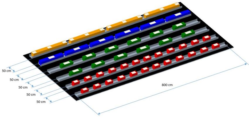
2                                                                                   Kumar Ankit∗ et al.

                                Brick     Dimension (cm)   Weight (kg)
                                Red        30 x 20 x 20         1
                                Green      60 x 20 x 20         1
                                Blue       120 x 20 x 20       1.5
                                Orange     180 x 20 x 20        2

                                    Table 1: Brick specifications

a conveyor belt is developed and implemented in [6]. In [7], a multi-degree of freedom manipulator
is developed which is controlled using classical controller and is employed for diverse tasks like pick
and place, insertion and valve turning. Pick and place operation of deformable objects is carried out
in [8] where point cloud is used to determine the feasibility of operation. The controller design of a
manipulator for indoor application is developed in [9] where, the applicability of the manipulator is
pick and place operation of unknown mass. Load transportation using aerial robots and cooperative
operations between aerial vehicles and aerial and ground vehicles is surveyed in [10] which analyzes
various kind of loads that could be transported and the stability of the resultant systems.
    Challenge 2 is one such scenario which requires UAVs and Unmanned Ground Vehicle (UGV)
to build a wall of given sequence. This involves the vehicles to autonomously search, detect, pick up
and place according to a given sequence. Given the specifications of the bricks to be used to achieve
the task, specially designed robotic manipulators and algorithms are needed to successfully execute
the challenge. In this paper, the software aspects of the challenge is taken care of, where a single
degree of freedom manipulator is employed to complete the challenge. Multiple aspects including
the vision, manipulation, path planning, multi-vehicle coordination and task assignment are also
addressed in this work.
    The paper is organised as: Section details the problem of building construction using UAVs and
UGV, as per the challenge specifications of MBZIRC 20. Section details the set up and architecture
developed in Robot Operating System (ROS) to address the problem. Section lays out the process
from a UAV perspective while Section 5 gives the same in UGV perspective. Section 6 details
the blanket layer of the entire system which takes care of multiple vehicles’ task allocation and
planning and other relevant aspects of the whole. Section 7 gives out simulation results and Section
9 concludes the paper.

2 Problem statement

Three UAVs and UGV collaborate to build separate walls in an arena is of size 50 m x 40 m x
20 m. There are four different type of bricks, varying in dimension and color, as given in Table 1.
The bricks are separately stacked for UAVs and UGV. The UAV stacks are distributed to aid easy
picking while the UGV stacks are uniform, as shown in Fig. 1. There is dedicated construction site
for the UAVs and the UGV. The UGV has to build the wall in the shape of ‘L’ which has an arm
length of 4 m and a height of 1 m. UAVs have a zig zag construction site as shown in Fig. 2. The
construction platform has a height of 1.7 m and has channel on top of it. The channel base is made
of wire mesh. This reduces the destabilizing effect of the UAV downwash while placing over the
channel. UAVs should build two layers of bricks over this channel. For UGV and UAVs, one 4 m
channel is reserved for the orange bricks. This paper details the algorithms and packages developed
for executing the entire challenge 2 in Robot Operating System (ROS) framework. The maximum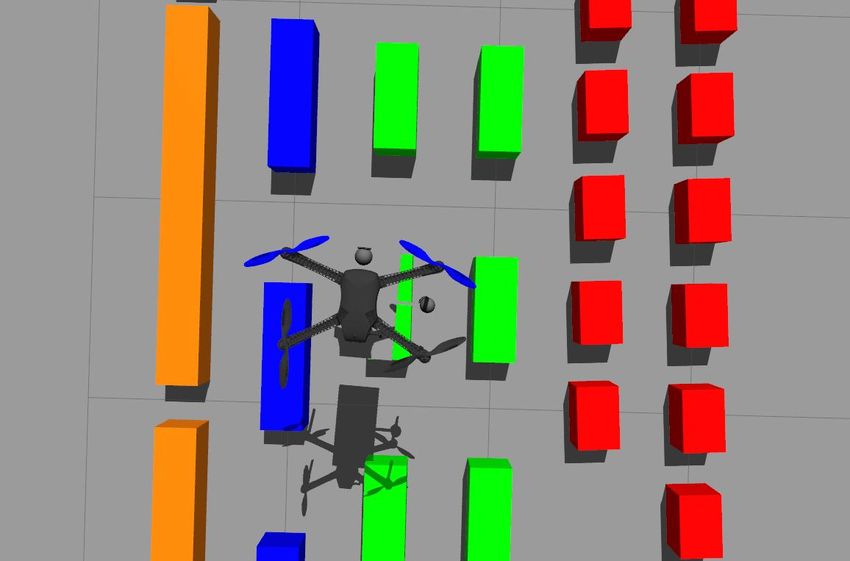
Multi Agent Collaboration for Building Construction                                                               3

                                      (b) Bricks with white labels marking
         (a) UAV brick stack                                                        (c) UGV brick stack
                                      the magnetic portion

                                             Fig. 1: Brick piles

      (a) UGV construction site            (b) UAV construction site         (c) UAV channel unit specification

                                  Fig. 2: Construction site for the vehicles

speed of UAVs are restricted to 15 kmph and that of UGV is restricted to 30 kmph due to safety
considerations.

3 ROS architecture

The simulations are visualised using Gazebo 9.11. Following environment is set up to meet the
competition specifications.

3.1 Arena

An arena is created in Gazebo with similar construction sites as specified by the competition
organisers. Three UAVs and one UGV is deployed in this environment. The arena is as shown in
Fig. 3.

3.2 UGV and UAVs

For simulating the UGV, model of Husky by Clearpathrobotics is ported into the Gazebo environ-
ment. This is integrated with a UR5 manipulator. The UR5 has a reach radius of 850 mm and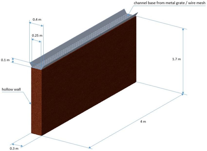
4                                                                                         Kumar Ankit∗ et al.

                                   Fig. 3: Challenge 2 arena in Gazebo

    (a) Husky UGV model with UR5 ma- (b) Iris drone with downward facing
                                                                           (c) Iris drone with manipulator
    nipulator                        camera

                                Fig. 4: Vehicle models used for simulation

payload of up to 5 kg. Two monocular cameras are employed in the UGV, one forward facing
and another downward facing. The forward facing one aids in search and exploration while the
downward facing camera on the manipulator is employed for pick and place operations.
   The UAVs use IRIS drone model. It’s a quad rotor and is equipped with downward facing
manipulator with electro-permanent gripping mechanism. Two monocular cameras are employed in
the UAV, one on the manipulator and another to the side. The camera on manipulator aids pick
operation while the sideways one helps in place operations. The UGV and UAV models are as in
Fig 4.

4 Wall building using UAV

The following sub tasks are involved in autonomous wall construction by a UAV.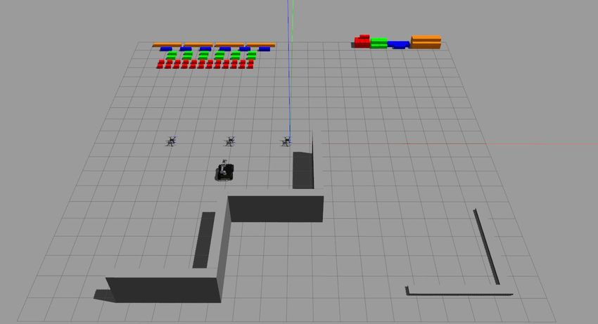
Multi Agent Collaboration for Building Construction                                                 5

                   Pick up

       Travel                     Decide

         Decide                   Travel

                    Place

                            (a)                                         (b)

Fig. 5: (a) The sequence of operation in pick and place (b) UAVs with at different assigned corridors

4.1 Arena exploration

Search is carried out to detect the locations of brick piles as well as the construction site for the
vehicles. For this, a downward facing camera is employed. The drone does exploration using a lawn-
mover pattern to identify the pile locations and construction site locations for both UAV and UGV.
This information is then shared to the master through ROS interface.

4.2 Pick and place operation

Challenge two requires repetitive motion of the vehicles between the brick stack and the construction
site with minimal interference with the paths of each other, as represented as in Fig. 5(a). The
two ‘decisions‘ blocks in Fig. 5(a) represent the process of choosing the placing location and pick
up channel for pick and place tasks, respectively. This involves dedicated path assignment for
the vehicles to optimise performance. The operation of pick and place involves the following sub
operations.

4.2.1 Path planning

Using the information from exploration, the UAV should traverse from the pile location to the
construction site. For this, a path is planned joining the locations. UAVs are assigned corridors at
different altitudes such that the vehicles won’t collide with each other, as shown in Fig. 5(b).

4.2.2 Vision based brick detection and alignment and pick up

Once the vehicles reach the location of pile, fine corrections are required in its position and orien-
tation so as to pick up the brick. For this, vision is employed. The feed from the downward facing
camera is processed to detect the brick. The detector uses segmentation to detect the white patch
on the brick. With the contours obtained, following information is determined.
 – Brick Center: This is computed based on the average value of the contour points.
 – Yaw: An ellipse is fitted to the polygon made from the contour points and the angle of the major
   axis in image plane is taken as desired yaw for the vehicle.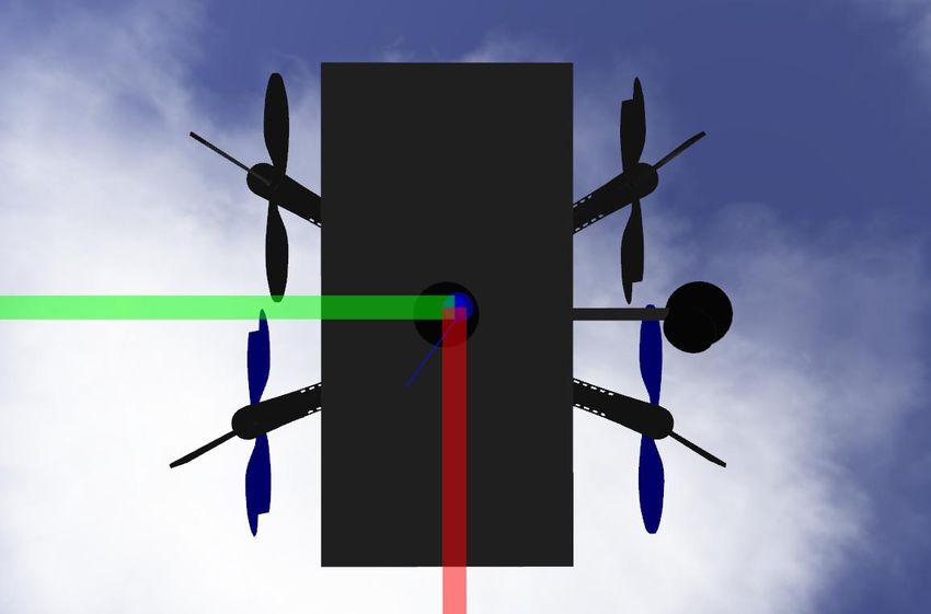
6                                                                                  Kumar Ankit∗ et al.

– Area: The total area under the polygon is taken and used as a depth parameter while descending
  to pickup.

Alignment is based on the center obtained using image processing. The drone positions above the
center of the brick by the following steps.

– Error is computed between camera center and brick center along both x and y axes as

                                        eCx = (bCx − wimg /2)

                                         eCy = (bCy − himg /2)

  where, eCx and eCy are computed error values, bCx and bCy correspond to the center of detected
  brick and wimg and himg are the width and height of the image captured.
– Desired velocities in X and Y axis are then obtained using a PD controller over the error in
  both the axes.
                                  Vx = kpCx ∗ eCx + kdCx ∗ (∆eCx )

                                   Vy = kpCy ∗ eCy + kdCy ∗ (∆eCy )

    where, kp and kd are the respective proportional and derivative gains.

When centered, the UAV yaws to align the brick along the manipulator using the yaw information
obtained from image processing.

                               ωz = kpyaw ∗ byaw + kdyaw ∗ (∆byaw )

where, ωz is the angular velocity of the UAV in vertical axis and byaw is the change in yaw from
desired and current yaw values. After aligning, UAV descends to touch down on the brick. Descend-
ing velocity is calculated by deploying a PD controller over the error between desired and current
area spanned by the brick in the image plane.

                                       earea = barea − darea

where, darea is desired area and barea is the instantaneous brick area visible to the camera. The
descend velocity is computed as

                              Vz = kparea ∗ earea + kdarea ∗ (∆earea )

While descending, the UAV may drift away from brick center or misalign. To tackle this the centering
and aligning check is carried out at each iteration of the PD loop. After reaching the proper height,
the Electro-Permanent Magnet is activated to attach the brick to the manipulator. After confirming
the attachment, the drone lifts off to its selected corridor height.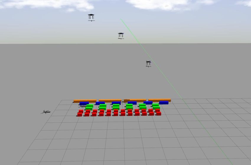
Multi Agent Collaboration for Building Construction                                                7

                                   (a)                          (b)

                    Fig. 6: (a) UAV in pick up mode (b) Downward camera frame

                       Fig. 7: Placement operation and camera views in process

4.2.3 Placing

Placing involves the following sub-tasks:
 – Channel detection: Near to construction site, the downward facing camera shifted sideways is
   engaged. The feed is then processed to generate the pose and orientation of the the channel, in
   case the placement happens directly over the channel or the nearest edge of a brick if placing
   over a layer.
 – Drop Pose Update: Based on the pose of the last edge detected, pose and orientation of the
   brick to be laid is updated.
 – Final Placement: To align the brick with the last laid brick, camera feed from the front cam is
   processed in a closed loop minimizing the error using a PD controller. The output from the PD
   controller is then used to update the pose and orientation of manipulator/agent in real time
   based on the feed. Once the manipulator reaches close to the placing point, the manipulator is
   disengaged to release the brick.

5 Construction using UGV

Similar sub-tasks are involved in pick and place using the ground vehicle. The major areas of
difference with respect to the UAV are in the following aspects.
 – Travel (To-Pick): Front camera feed is utilized to detect the center and area of the brick to be
   picked. Center information of a detected brick is used to orient the UGV and the area information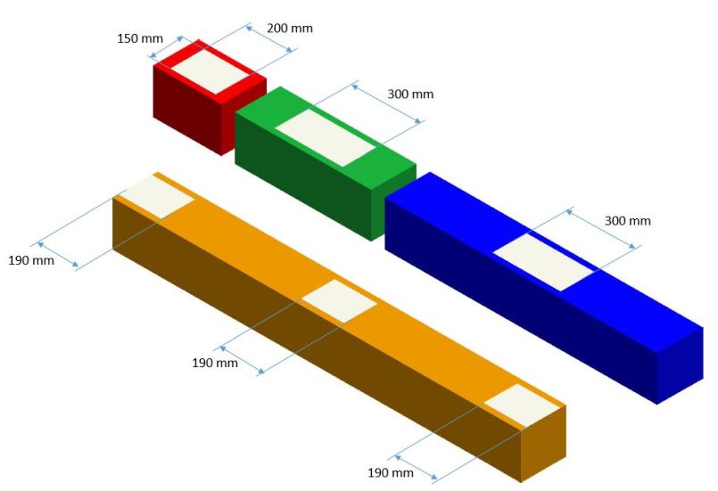
8                                                                                   Kumar Ankit∗ et al.

                                         P1       P2         P3

                                              Orange stack

                                               Blue stack

                                              Green stack

                                               Red stack

Fig. 8: The UAV pile division to aid multi-UAV pick without collision. Three partitions are consid-
ered here.

    is used to estimate how far the brick is. This information is then fed to a PD control to generate
    forward velocity and yaw rate for the UGV.
                                        V = kpv ∗ (darea − barea )
                                         eCx = (bCx − wimg /2)
                                     ωz = kpz ∗ eCx + kdz ∗ (∆eCx )
  where, V is computed velocity of the UGV, kpz and kdz are respective proportional and deriva-
  tive gains, darea is desired area and barea is the captured brick area.
– Pick Task: The pose and orientation of manipulator arm with respect to robot chassis is used
  to compute joint angles based on Inverse Kinematics equations.
   – The UGV is guided so as to attain desired [x, y, z] for the manipulator
   – Orientation: For picking operation, the gripper mostly faces vertically down. MOVE-IT pack-
      age is used for this purpose.
– Travel (to place): The drop location depends upon the picked brick and the closest available
  drop location. For the UGV to place, the drop position should be in the configurational space
  of the manipulator.
– Placing: Upon reaching the placing location, following sub-tasks are initiated.
   – Image Processing: When near to the center but far enough to see the last edge of nearby
      placed brick, location of the edge is computed in local frame.Based on the image feed of front
      camera the orientation of the last laid brick with respect to camera is computed.
   – Drop Pose Update: Based on the pose and orientation of the detected edge, pose and orien-
      tation for the brick to be placed is computed.
   – Manipulator Arm Engagement: The manipulator picks the brick back from the carrier, then
      reaches the position and the orientation computed using inverse kinematics.
   – Final Placement: A similar placement procedure is followed as that of UAV.

6 Mission Execution

The sub tasks mentioned in previous section needs to be invoked based on the real time events.
A single command evokes the mission planner, which will be running at Ground Control Station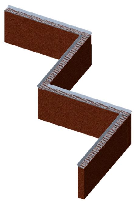
Multi Agent Collaboration for Building Construction                                                   9

(GCS). The external planner needs to have sufficient features not only to take care of the major
operations involved but also to handle external events like fail safe, collision avoidance, trial reset,
unexpected system reboot, communication loss etc. The features that are available in the developed
mission planner are detailed below.
1. Dashboard: This module is responsible for keeping and updating the complete database of
   challenge variables. The major data handled are:
    – Pickup Spots: Information of pickup spots including their pose, status, type of brick in it
       and the points that can be gained from it. This will help to determine free/unhindered spots
       in the pickup zone.
    – Placement Spots: Information of placements spots including pose, status, layer information
       (bricks required). This will help determine where to place the picked-up brick and to deter-
       mine the next required brick to be picked.
2. Decision Making: Based on certain cost functions, the agents are chosen which are best
   suitable for each immediate operation.
3. Task Allocation: After the decision is made, proper task allocation and regular monitoring on
   the task is necessary and necessary actions are to be taken if any agent is fails to deliver the
   task. This is taken care by the task allocation module.
4. Fault Handling: In case of any failure the master needs to be aware of what kind of fail-
   ure happened and how to ensure further continuity. Some of the failure scenario that can be
   encountered as:
    – Agent Connectivity Loss
    – Brick Pick Fail
    – Brick Place Fail
    – Collision between the agents
    – Reset/Pause Scenario
5. Layer Handling: Given the layer pattern the task is to extract the pose and orientation of
   each prick in the channel. This information is crucial is decision making process to select from
   the nearest drop position available for the picked brick.
6. Multi-Agent Co-ordination: This include the following sub parts.
    – Inter-Agent Collision Avoidance: Since multiple agents are involved in the task, there is
       always a chance of collision. This module ensures enough separation between the agents while
       travelling, pickup and place. To further reduce the risks of collisions certain constraints are
       imposed in the strategy.
    – Corridor: The agents are constrained to choose a corridor from three specified heights de-
       pending upon the brick they are carrying. The three specified heights to choose from are 3m,
       5m and 7m from the ground. Heavier the brick, lower the corridor is chosen to ensure lesser
       path to travel and lesser turbulence to handle. Even if they happen to cross each other while
       travelling, the agents will still be separated by a vertical distance of at least 2m.
7. Blocking occupied channel: Once the channel is selected for an agent to place, it is blocked for
   other agents not to choose from. This ensure that the placement task is carried out unhindered.
8. Pickup Channel Scoring: As the pile location is divided into 3 separate arrays with 4 types of
   brick in each array, there are 12 spots to choose from. This constraint ensures that any pickup
   spot close to currently picking agent will possess higher cost to select from. Hence this will drive
   agents to choose most unhindered spot again avoiding collision chances.
9. Task Handler: This module is responsible for allocating tasks along with keeping track of
   agents and the tasks allocated. Following information is passed into this module.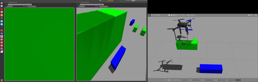
10 Kumar Ankit∗ et al.
– Task Query: For passing the determined tasks to free agent in proper format
– Task Status: For passing status of the agent and the task allocated
Using above two information the handler will be able to allocate task as well as keep track of
each of the tasks allocated as whether engaged/completed/failed. The tasks will be allocated
according to priority (based on gain/cost) with collision avoidance running in background always
to ensure safe operation.
10. Task Scheduler: This is the core of decision-making system which encodes the strategy chosen
to drive the agents to complete the challenge as soon as possible with as much points. When
queried by any free agent, this decides the task to be allocated to the agent by determining
cost and the gain involved in the overall operation. This is done numerically by defining certain
functions and matrices.Cost and gain functions include:
– Pickup Cost: This is the cost included in choosing the colour and the spot to pick the chosen
colour brick. This helps to determine least hindered place to pick from. Numerically a score
matrix of size 4x3 in handling the hindrance involved
for UAVs is initialised as
111
1 1 1
Score= 1 1 1
111
Upon selection of a particular row and column, say element (2,2), the cost increments happens
as:
131 1 1/3 1
3 5 3 1/3 1/5 1/3
Kernel to increase cost: 1 3 1 Kernel to reset cost: 1 1/3 1
131 1 1/3 1
– Travel Cost: Includes the time taken to travel from pickup spot to building site or vice versa
and the height corridor chosen to transport the brick. This will drive the agents to choose
the shortest path and the lowest corridor for the heaviest brick. This cost is
Csttr = ktr ∗ |loctarg − loccurrent |
where, Cst is the cost incurred, ktr is the gain.
– Placement Cost: This will help to determine least hindered placement spot and will ensure
no other agent enters the channel while one is already placing.
– Points: This determines the gain achieved in completing a task based on the colour of the
brick involved. The gain matrix is
10 10 10
6 6 6
Points= 4 4 4
3 3 3
As shown in the sequence loop, there are two states at which we must decide what to choose.
(a) When Picked: This decision loop will include the placement and the travel cost to deter-
mine the best spot to drop the picked brick using the following equation,
Cstdrop = Cstplacement + Csttr
(b)) When Dropped/Free: This decision loop will include the travel and pickup cost along
with the points gain to determine the colour and spot to choose from using the following
equation,
Cstpick = Cstspot + CsttrMulti Agent Collaboration for Building Construction 11
Fig. 9: Lawn-mover pattern employed by the UAV to explore the arena
7 Simulation Results and Discussion
The simulating platform is Intel i7 octa-core with 16 GB RAM. This works on Ubuntu 16.04 and
ROS kinetic.
7.1 UAV operations
Fig. 9 shows the search pattern followed by the UAVs to detect the brick piles and construction
sites for both the UAVs and UGV. The pattern makes sure that the entire arena is explored. The
width of this pattern in implementation is decided by the camera FoV. Wider FoV cameras could
effectively reduce the number of iterations that the UAV takes to cover the arena. Fig. 10 gives the
error profiles in pixels for picking and placing operations of the UAVs. As can be seen in Fig. 10(a),
the PD controller aligns the vehicle and eventually pushes the error to zero for precise pick up of the
brick. Fig. 10(b) gives a similar profile for placement. Fig. 11 shows the trajectories of the UAVs
from take-off until placement of one layer. The drone corridors associated with the architecture
makes sure that the vehicles are placed at sufficient separation from each other.
The entire operation process of the UAVs can be found in 1 .
7.2 UGV operations
The UGV operations start once the UAV finishes its exploration. The UGV receives the GPS
coordinates of its brick stack and starts moving towards the same. Upon detecting different colors,
1 UAV operations12 Kumar Ankit∗ et al.
(a)
(b)
Fig. 10: UAV error profiles in pick and place operations
Fig. 11: UAV corridors to avoid collision: trajectories
fine corrections are made to direct the vehicle to the specific brick which is decided based on the
given sequence. Fig. 12 gives the error plots of UGV trajectory and heading while correcting itself
to the brick to be picked up and joint angle profiles in the process of picking up the brick.Multi Agent Collaboration for Building Construction 13
(a) (b) (c)
Fig. 12: UGV error profiles in trajectory and heading and joint angle profiles
(a) (b)
(c) (d)
Fig. 13: Snap shots of UGV approaching green brick and respective camera frames denoting the
center of detected bricks
Fig. 13 shows the snap shots of UGV proceeding to pick a brick. The entire operation process
of the UAVs can be found in 2 .
2 UGV operations14 Kumar Ankit∗ et al. 8 Discussion This work is intended to be a reference material for an end-to-end development of software flight stack and peripheral task planner for building a wall using multiple UAVs and UGV. This includes control, guidance, vision and manipulation aspects of the entire system. Nevertheless, there are cer- tain aspects of improvement which could be appended to this work to make it more innovative. One among this is UAV-UGV Collaboration. In the current work, UAVs collaborate among themselves to build the structure while UGV build its structure on its own. But, as UAVs could finish the work faster compared to the UGV, the UAVs could assist in speeding up the UGV wall building. Certain aspects which would be appended in the future extensions of this work would be – Intermediate Drop-Pickup Zone: This type of collaboration is helpful in UGV construction site. Since the agility of UGV is very less compared to the UAVs, UAVs could be deployed to carry the bricks from the UGV pile location to an intermediate drop location near to UGV construction site. The bricks carried by the UAVs will be placed in proper pose and orientation nearby so as the UGV need not traverse much in collecting bricks for construction. This will overall improve the speed of layer building for UGV. – Heavy/In Bulk Brick Carriage: This strategy involves UGV to carry brick in bulk amount (at least 3 or depending upon the agent requirements) from the UAV pile location and drop near to UAV construction site. This will greatly reduce the time UAVs spent carrying the bricks in the turbulent environment. This is especially applicable for orange brick which is the longest one and which causes issues for the UAVs to carry on its own. Multi-UAV collaboration to pick longest brick is another aspect which is to be addressed. This capability would accelerate the UAV wall building where the orange bricks could be placed with better precision and ease. 9 Conclusions This paper is motivated by MBZIRC 2020 challenge 2 which involves picking and placing of objects of different sizes and weights so as to build a structure. The complete software framework involved is described in this which details each and every aspect required for the successful execution of the challenge. This includes the operations of both UAV as well as UGV. The complete pipeline required for the challenge is developed which uses classical methods to carry out the challenge in ROS-Gazebo framework. Simulation results verify this ready to implement framework. Implementation on real hardware is under progress and would be reported in near future publications. Acknowledgements We would like to acknowledge the Robert Bosch Center for Cyber Physical Systems, Indian Institute of Science, Bangalore, and Khalifa University, Abu Dhabi, for partial financial support. We would also like to thank fellow team members from IISc for their invaluable contributions towards this competition. References 1. Garimella G, Kobilarov M. Towards model-predictive control for aerial pick-and-place. In2015 IEEE international conference on robotics and automation (ICRA) 2015 May 26 (pp. 4692-4697). IEEE. 2. Huang Y, Chiba R, Arai T, Ueyama T, Ota J. Robust multi-robot coordination in pick-and-place tasks based on part-dispatching rules. Robotics and Autonomous Systems. 2015 Feb 1;64:70-83.
Multi Agent Collaboration for Building Construction                                                              15

3. Shete PP, Jaju A, Bose SK, Pal P. Stereo vision guided telerobotics system for autonomous pick and place
  operations. InProceedings of the 2015 Conference on Advances in Robotics 2015 Jul 2 (pp. 1-6).
4. Tan H, Xu Y, Mao Y, Tong X, Griffin WB, Kannan B, DeRose LA. An integrated vision-based robotic manipu-
  lation system for sorting surgical tools. In2015 IEEE International Conference on Technologies for Practical Robot
  Applications (TePRA) 2015 May 11 (pp. 1-6). IEEE.
5. Teodorescu CS, Vandenplas S, Depraetere B, Anthonis J, Steinhauser A, Swevers J. A fast pick-and-place pro-
  totype robot: design and control. In2016 IEEE Conference on Control Applications (CCA) 2016 Sep 19 (pp.
  1414-1420). IEEE.
6. Hwang YS, Wang L, Lee DH, Lee JM. Vision based machine for pick-and-place operation. DEStech Transactions
  on Materials Science and Engineering. 2016(icimm).
7. Orsag M, Korpela C, Bogdan S, Oh P. Dexterous aerial robotsmobile manipulation using unmanned aerial systems.
  IEEE Transactions on Robotics. 2017 Oct 5;33(6):1453-66.
8. Jrgensen TB, Jensen SH, Aans H, Hansen NW, Krger N. An adaptive robotic system for doing pick and place
  operations with deformable objects. Journal of Intelligent and Robotic Systems. 2019 Apr 15;94(1):81-100.
9. Sun D, Wan N, Dai W, Zhang Y, Hovakimyan N. Control Design for an Aerial Manipulator for Pick-and-Place
  Tasks. InAIAA Scitech 2019 Forum 2019 (p. 1291).
10. Villa DK, Brando AS, Sarcinelli-Filho M. A Survey on Load Transportation Using Multirotor UAVs. Journal of
  Intelligent & Robotic Systems. 2019 Oct 14:1-30.
You can also read