Multimode Laser Diodes - LDX Optronics Inc. 2021 Catalog - RPMC Lasers, Inc.
←
→
Page content transcription
If your browser does not render page correctly, please read the page content below
Multimode
     Laser
   Diodes

     LDX Optronics Inc.
         2021 Catalog
LDX Optronics Inc.

                          445nm-665nm Laser Diodes                             3

                          680nm-760nm Laser Diodes                             4

                          780nm-830nm Laser Diodes                             5

                          860nm-1030nm Laser Diodes                            6

                          1064nm-1850nm Laser Diodes                            7

                          Laser Diode Arrays                                   8

Table of                  Part Numbering System                                9

Contents                  Standard Packages and Options

                          General Precautions
                                                                              10

                                                                              26

                          Thermal Management                                  27

                          Open Laser Diode Packages Precautions               29

                          Sealed Laser Diode Packages                         31

                          Distributors                                        32

                          About LDX Optronics & RPMC Lasers                   34

                                                                  8495 Veterans Memorial Pkwy,
                          LDX Optronics Inc.                      O'Fallon MO 63366 Phone (636)
                                                                  272-7227 diodes@rpmclasers.com

                              2021 Catalog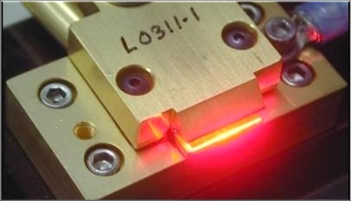
LDX Optronics Inc.

                                                                445nm-665nm Laser Diodes
                                                               Output Min Fiber                                                                               Spectral
                                                        Output                  Min Fiber           Threshold Operating Operating     Beam           Beam
                                   Wavelength Emitter           from Size HHL             Operating                                                            Width Polariz   Acceptable
                    Part Number                         Power                   Size 9mm             Current Current Voltage       Divergence     Divergence
                                     (nm)     Size (um)         Fiber  & BTF              Temp (°C)                                                             (nm)   ation    Packages
                                                        (mW)                    SMA (um)            (mA) Typ. (mA) Typ. (V) Typ. (FWHM) θ// (°) (FWHM) θ⊥ (°)
                                                               (mW)     (um)                                                                                   FWHM

                                        8495 Veterans Memorial Pkwy, O'Fallon MO 63366 Phone (636) 272-7227
                                        diodes@rpmclasers.com
Revised: 6/2/2021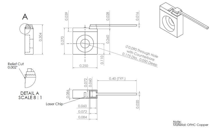
LDX Optronics Inc.

                                                                 680nm-760nm Laser Diodes
                                                               Output Min Fiber                                                                               Spectral
                                                        Output                  Min Fiber           Threshold Operating Operating     Beam           Beam
                                   Wavelength Emitter           from Size HHL             Operating                                                            Width Polariz   Acceptable
                    Part Number                         Power                   Size 9mm             Current Current Voltage       Divergence     Divergence
                                     (nm)     Size (um)         Fiber  & BTF              Temp (°C)                                                             (nm)   ation    Packages
                                                        (mW)                    SMA (um)            (mA) Typ. (mA) Typ. (V) Typ. (FWHM) θ// (°) (FWHM) θ⊥ (°)
                                                               (mW)     (um)                                                                                   FWHM

                                        8495 Veterans Memorial Pkwy, O'Fallon MO 63366 Phone (636) 272-7227
                                        diodes@rpmclasers.com
Revised: 6/2/2021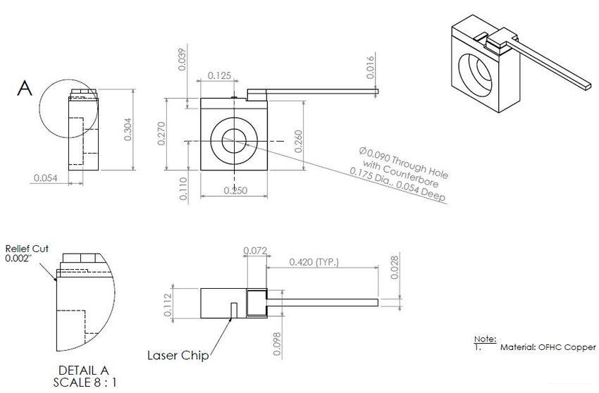
LDX Optronics Inc.

                                                                  780nm-830nm Laser Diodes
                                                              Output Min Fiber                                                                               Spectral
                                                       Output                  Min Fiber           Threshold Operating Operating     Beam           Beam
                                  Wavelength Emitter           from Size HHL             Operating                                                            Width Polariz   Acceptable
                    Part Number                        Power                   Size 9mm             Current Current Voltage       Divergence     Divergence
                                    (nm)     Size (um)         Fiber  & BTF              Temp (°C)                                                             (nm)   ation    Packages
                                                       (mW)                    SMA (um)            (mA) Typ. (mA) Typ. (V) Typ. (FWHM) θ// (°) (FWHM) θ⊥ (°)
                                                              (mW)     (um)                                                                                   FWHM

                                          8495 Veterans Memorial Pkwy, O'Fallon MO 63366 Phone (636) 272-7227
Revised: 6/2/2021                         diodes@rpmclasers.com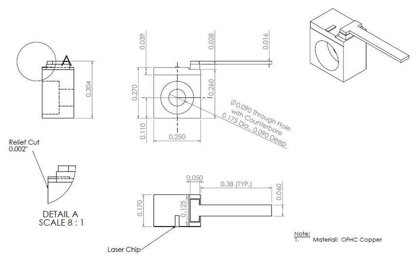
LDX Optronics Inc.

                                                              860nm-1030nm Laser Diodes
                                                               Output Min Fiber                                                                               Spectral
                                                        Output                  Min Fiber           Threshold Operating Operating     Beam           Beam
                                   Wavelength Emitter           from Size HHL             Operating                                                            Width Polariz   Acceptable
                    Part Number                         Power                   Size 9mm             Current Current Voltage       Divergence     Divergence
                                     (nm)     Size (um)         Fiber  & BTF              Temp (°C)                                                             (nm)   ation    Packages
                                                        (mW)                    SMA (um)            (mA) Typ. (mA) Typ. (V) Typ. (FWHM) θ// (°) (FWHM) θ⊥ (°)
                                                               (mW)     (um)                                                                                   FWHM

                                        8495 Veterans Memorial Pkwy, O'Fallon MO 63366 Phone (636) 272-7227
                                        diodes@rpmclasers.com
Revised: 6/2/2021
LDX Optronics Inc.

                                                             1064nm-1850nm Laser Diodes
                                                               Output Min Fiber                                                                               Spectral
                                                        Output                  Min Fiber           Threshold Operating Operating     Beam           Beam
                                   Wavelength Emitter           from Size HHL             Operating                                                            Width Polariz   Acceptable
                    Part Number                         Power                   Size 9mm             Current Current Voltage       Divergence     Divergence
                                     (nm)     Size (um)         Fiber  & BTF              Temp (°C)                                                             (nm)   ation    Packages
                                                        (mW)                    SMA (um)            (mA) Typ. (mA) Typ. (V) Typ. (FWHM) θ// (°) (FWHM) θ⊥ (°)
                                                               (mW)     (um)                                                                                   FWHM

                                        8495 Veterans Memorial Pkwy, O'Fallon MO 63366 Phone (636) 272-7227
                                        diodes@rpmclasers.com
Revised: 6/2/2021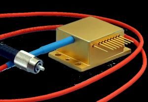
LDX Optronics Inc.
660nm-1064nm Diode Arrays
Output Min Fiber Spectral
Output Min Fiber Threshold Operating Operating Beam Beam
Wavelength Emitter from Size HHL Operating Width Polariz Acceptable
Part Number Power Size 9mm Current Current Voltage Divergence Divergence
(nm) Size (um) Fiber & BTF Temp (°C) (nm) ation Packages
(mW) SMA (um) (mA) Typ. (mA) Typ. (V) Typ. (FWHM) θ// (°) (FWHM) θ⊥ (°)
(mW) (um) FWHM
LDX-4119-660 660 ±5 nm 100 x 19 10 N/A N/A N/A 15 9400 21000 2.1 7 40 1 TE CS Package
LDX-4119-670 670 ±5 nm 100 x 19 10 N/A N/A N/A 15 9400 21000 2.1 7 40 1 TE CS Package
LDX-4119-680 680 ±3 nm 150 x 19 12 N/A N/A N/A 15 9000 24000 2.5 7 40 1 TE CS Package
LDX-4119-690 690 ±3 nm 150 x 19 12 N/A N/A N/A 15 6500 22000 2.3 7 36 1 TE CS Package
LDX-4219-730 730 ±5 nm 150 x 19 20 N/A N/A N/A 20 12000 28000 1.9 7 26 1 TM CS Package
LDX-4224-750 750 ±5 nm 100 x 24 20 N/A N/A N/A 20 12000 28000 1.9 7 26 1 TM CS Package
LDX-4219-760 760 ±5 nm 150 x 19 20 N/A N/A N/A 20 12000 28000 1.9 7 26 1 TM CS Package
LDX-4319-795 795 ±5 nm 150 x 19 30 N/A N/A N/A 20 10000 28000 1.9 7 26 2 TM CS Package
LDX-4424-1064 1064 ±10 nm 100 x 24 40 N/A N/A N/A 20 5000 30000 1.4 7 38 5 TE CS Package
LDX-4419-1064 1064 ±10 nm 150 x 19 40 N/A N/A N/A 20 5000 30000 1.4 7 38 5 TE CS Package
Other Array Wavelengths Available by Request
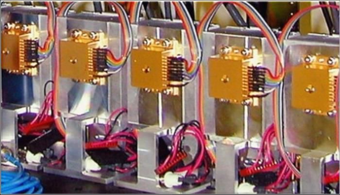
Standard Bar Package: CS Package
8495 Veterans Memorial Pkwy, O'Fallon MO 63366 Phone (636) 272-7227
diodes@rpmclasers.com
Revised: 6/2/2021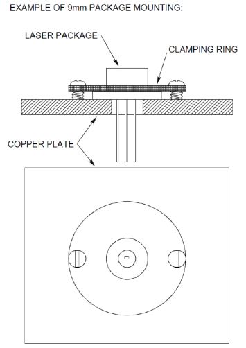
LDX Optronics Inc.

                                              Part Numbering System

                       8495 Veterans Memorial Pkwy, O'Fallon MO 63366 Phone (636) 272-7227
                       diodes@rpmclasers.com
Revised: 6/2/2021
LDX Optronics Inc.

                                       Standard Package Types
                            Free Space Packages                      Fiber Coupled Packages

                    C-Mount (1)
                    Medium C-Mount (2)
                    Thick C-Mount (3)                          9mm SMA FC
                                                               Package (11)                                     Standard / Optional Features
                    B-Mount (4)
                                                                                                      Package Type Package #   PD    Thermistor   TEC   FAC
                                                                                                      Cstd             1       NO       NO        NO    O
                                                               8-pin HHL FC                           Cmed             2       NO       NO        NO    O
                    Q-Mount (5)                                Package (13)                           Cthick           3       NO       NO        NO    O
                                                               w/o TEC (14)                           B                4       NO       NO        NO    O
                                                                                                      Q                5       NO       NO        NO    O
                                                                                                      COS              6       NO       NO        NO    O
                    Chip on Submount (6)
                                                                                                      9MM              7       YES      NO        NO    O
                                                                                                      TO3 w TEC        8       YES      YES       YES   O
                                                               HHL FC                                 TO3 w/o TEC      9        O        O        NO    O
                    9mm Package (7)                            Package (12)                           HHL             10       YES      YES       YES   O
                                                                                                      9MM SMA         11       YES      NO        NO    NO
                                                                                                      HHLFC           12       YES      YES       YES   NO
                    TO-3 Package (8)                                                                  BFC TEC         13       YES      YES       YES   NO
                    w/o TEC (9)                                                                       BFC w/o TEC     14       YES      YES       NO    NO
                                                               2-pin FC                               FCP             15       NO       NO        NO    NO
                                                               Package (15)                           CHIP            16       NO       NO        NO    NO
                    HHL Package (10)                                                                  BAR             17       NO       NO        NO    NO
                                                                                                      O - Optional

                                       8495 Veterans Memorial Pkwy, O'Fallon MO 63366 Phone (636) 272-7227
                                       diodes@rpmclasers.com
Revised: 6/2/2021
LDX Optronics Inc.
C- Mount Standard
8495 Veterans Memorial Pkwy, O'Fallon MO 63366 Phone (636) 272-7227
diodes@rpmclasers.com
Revised: 6/2/2021LDX Optronics Inc.
C- Mount Medium
8495 Veterans Memorial Pkwy, O'Fallon MO 63366 Phone (636) 272-7227
diodes@rpmclasers.com
Revised: 6/2/2021LDX Optronics Inc.
C- Mount Thick
8495 Veterans Memorial Pkwy, O'Fallon MO 63366 Phone (636) 272-7227
diodes@rpmclasers.com
Revised: 6/2/2021LDX Optronics Inc.
B – Mount Package
8495 Veterans Memorial Pkwy, O'Fallon MO 63366 Phone (636) 272-7227
diodes@rpmclasers.com
Revised: 6/2/2021LDX Optronics Inc.
Q – Mount Package
8495 Veterans Memorial Pkwy, O'Fallon MO 63366 Phone (636) 272-7227
diodes@rpmclasers.com
Revised: 6/2/2021LDX Optronics Inc.
Chip on Submount Package
8495 Veterans Memorial Pkwy, O'Fallon MO 63366 Phone (636) 272-7227
diodes@rpmclasers.com
Revised: 6/2/2021LDX Optronics Inc.
9mm Package
8495 Veterans Memorial Pkwy, O'Fallon MO 63366 Phone (636) 272-7227
diodes@rpmclasers.com
Revised: 6/2/2021LDX Optronics Inc.
TO-3 Package
8495 Veterans Memorial Pkwy, O'Fallon MO 63366 Phone (636) 272-7227
diodes@rpmclasers.com
Revised: 6/2/2021LDX Optronics Inc.
HHL Package
8495 Veterans Memorial Pkwy, O'Fallon MO 63366 Phone (636) 272-7227
diodes@rpmclasers.com
Revised: 6/2/2021LDX Optronics Inc.
HHL Package Window Detail
8495 Veterans Memorial Pkwy, O'Fallon MO 63366 Phone (636) 272-7227
diodes@rpmclasers.com
Revised: 6/2/2021LDX Optronics Inc.
9mm Fiber Coupled Package
8495 Veterans Memorial Pkwy, O'Fallon MO 63366 Phone (636) 272-7227
diodes@rpmclasers.com
Revised: 6/2/2021LDX Optronics Inc.
8-pin HHL Fiber Coupled package
8495 Veterans Memorial Pkwy, O'Fallon MO 63366 Phone (636) 272-7227
diodes@rpmclasers.com
Revised: 6/2/2021LDX Optronics Inc.
2-pin Fiber Coupled Package
8495 Veterans Memorial Pkwy, O'Fallon MO 63366 Phone (636) 272-7227
diodes@rpmclasers.com
Revised: 6/2/2021LDX Optronics Inc.
HHL Fiber Coupled Package
8495 Veterans Memorial Pkwy, O'Fallon MO 63366 Phone (636) 272-7227
diodes@rpmclasers.com
Revised: 6/2/2021LDX Optronics Inc.
CS Package
8495 Veterans Memorial Pkwy, O'Fallon MO 63366 Phone (636) 272-7227
diodes@rpmclasers.com
Revised: 6/2/2021• Special wavelength
LDX Optronics Inc. diodes and especially diodes in the red are much, much more susceptible to damage
than standard infrared diodes.
General • Think about how you are employing the diodes to make sure you are doing everything possible to get a
long lifetime. We want you to have a success using these products.
•
Precautions Keep the diodes clean. They should not be operated in an environment where dust particles in the air can
reach the active region (output facet) of the diode.
• Keep the output facet (which emits light) dry. If you store the unit in a high humidity, the optical coatings
can be damaged and render the diode useless.
• Operating the laser diode at a temperature lower than recommended will usually slightly increase the
output power (higher efficiency) and improve lifetime.
• Operating the laser diode at a temperature higher than recommended will increase the threshold current
and decrease the slope efficiency.
• Laser diodes need to be operated with an approved power supply/driver or they may be damaged and/or
destroyed quickly. Off-the-shelf drivers can deliver a high spike of current at turn-on, and they can deliver a
very short duration reverse biasing when the unit is turned off. Either of these will damage and/or destroy
the diode laser.
• The power supply/driver should be current-regulated and specifically designed for laser diodes. The power
supply should create no surges or spikes, no reverse voltages and should not have any ringing. Many poorly
designed power supplies have voltage transients during turn-on, turn-off, or in the case of power failure.
• Never make the connection to the laser diode with the power supply voltage on. Most laser diode power
supplies have provision to disable the supply and short the output to allow for connection of the diode.
• Laser diodes are very sensitive to damage by electrostatic discharge (ESD), or other voltage transients. The
laser should be handled using static-safe procedures when it is taken out of its static-protective shipping
container. When the laser is not connected to a power supply, the user should short the anode and cathode
together to prevent static damage.
• Some laser diodes are susceptible to damage from back reflections into the device. This is more the case
with lower wavelength material than with higher wavelengths. Thus, if attempting to collimate the output,
care must be taken to avoid back reflections.
• The emission wavelength changes with temperature: the wavelength changes about +1 nm for every 6° C
increase in temperature. This value varies by wavelength.
8495 Veterans Memorial Pkwy, O'Fallon MO 63366 Phone (636) 272-7227
diodes@rpmclasers.com
Revised: 6/2/2021• Heat: This is the biggest cause of field failures.
LDX Optronics Inc.
Thermal • Some laser diodes are more sensitive than others to the operating temperature. Red laser diodes tend to be
more temperature sensitive than the infrared laser diodes.
•
Management •
Many customers do not appreciate the importance and/or the complexity of removing waste heat.
Because operating temperature has a strong influence on laser lifetime, the heatsinking of the laser package is
of tremendous importance and doing it well is not as simple as many assume it is.
Precautions: • Waste heat must be removed efficiently and instantaneously, or the laser will heat up and burn out, or, as a
minimum, experience an abbreviated lifetime.
• The laser can be operated at higher temperatures than recommended, but the lifetime of the laser is reduced
exponentially as the operating temperature is increased.
• The diode package should be attached to a heatsink plate at least several millimeters thick.
• The heatsink must be capable of dissipating the waste heat generated by the laser diode. High power laser
diodes are typically 10 – 50% efficient at converting electricity into light. The remainder of the electrical input
power is dissipated as heat. Therefore, there may be several watts of waste heat generated by the laser.
Because so much heat is generated within the small area, it is critical that the laser is securely connected to an
adequate heatsink
• The best heatsink material is copper, but aluminum is also a fair heat conductor. If aluminum is used, the
surface should not be anodized in the region where the laser package makes contact with the heatsink. The
aluminum oxide anodized coating makes an effective thermal insulator.
• The surface of the heatsink should be machined flat and smooth where it will contact the back of the laser
package to allow for efficient heat transfer.
• Thermal compound, or an indium foil washer can be used to reduce the thermal impedance of this interface.
Our experience is that indium foil offers negligible improvement over a good copper-to-copper interface. In
permanent installations, some improvement of the heatsinking can be achieved using a silver-filled epoxy at
this interface. If silver-filled epoxy is used, it should be a “space qualified” low outgassing. To avoid
contamination of the laser facets (Epoxy Technology H21D, for example)
• The heatsink may be cooled by air, water, or thermoelectric coolers. Depending on the type of laser, an air-
cooled heatsink may provide sufficient cooling, as long as the application does not require stability of the laser
wavelength and output power. Most often, active cooling of the heatsink must be used. Active cooling usually
is either water-cooling, or thermoelectric coolers (TEC’s).
• Finally, when testing out a heatsink configuration, it is wise to test the temperature drop between the laser
package and the heatsink using a very small thermocouple touched against the base of the package. The
temperature drop during laser operation should be only 1-2 ° C.
8495 Veterans Memorial Pkwy, O'Fallon MO 63366 Phone (636) 272-7227
diodes@rpmclasers.com
Revised: 6/2/20211. Free space packages can be either a simple open heatsink or a sealed TO can type package. With open
LDX Optronics Inc.
Precautions heatsinks there is no protection for the delicate laser chip. The laser chip is very fragile and must be
protected from any mechanical contact. The exposed laser facets (mirror coatings) must not be
contaminated with any foreign material. Facet contamination can cause immediate and permanent
for Free damage to the laser. You should not blow on the laser, or expose the laser to smoke, dust, oils, or adhesive
fumes.
2. The laser facets are sensitive to accumulation of dust. When the laser is operating, dust particles tend to be
Space attracted to the laser facet. As the dust particles enter the intense optical field at the laser facet, they burn,
and the residues accumulate in the laser facet. Unless the laser is operated in a true “class 100” clean-room
Packages: environment, this dust accumulation will occur, even in a seemingly clean “lab environment. This kind of
contamination does not occur very rapidly, but over several hundred hours of operation in a normal room
environment, an open heatsink laser will show tiny “specks” on the lasers facet under microscopic
examination. These will gradually degrade the laser prematurely. If an open heatsink laser is to be operated
outside of a clean-room for more than short periods, it should be packaged within a sealed container to
prevent this dust accumulation. This does not require a true hermetic sealing of the laser. An epoxy seal or
o-ring seal around the laser assembly is perfectly sufficient.
C-Mount Package:
1. To operate, the C-mount must be screwed down securely to a heatsink using a #2-56 (English) or M-2
(metric) screw. The C-mount has a swallow counterbore around the mounting hole, for applications which
require close mounting of a component in front of the laser. A shallow binding head screw, or a button
head cap screw can be used in this situation.
2. Thermal grease should not be used with a C-mount. Most thermal greases tend to “creep” and the material
will eventually contaminate the diode facets.
3. The copper C-mount is the laser diode anode (+) terminal, so the power supply anode connection is best
made to the heatsink. Do not attempt to solder directly to the copper C-mount. The laser diode cathode (-)
terminal is the wire lead attached to the C-mount. Connection to this lead can be made either by soldering,
or by using a small, high quality, spring contact socket. The best sockets of this type have four contact
fingers, and the fingers are gold-plated (see for example parts made by Mill-Max).
4. Great care must be used if soldering to the cathode wire lead. The soldering is best done with the C-mount
already attached to the heatsink. This will prevent the body of the laser from heating up excessively. The
cathode lead itself can withstand high temperature, but the main part of the laser.
8495 Veterans Memorial Pkwy, O'Fallon MO 63366 Phone (636) 272-7227
diodes@rpmclasers.com
Revised: 6/2/2021LDX Optronics Inc.
Precautions C-Mount Package: (cont)
for Free block must remainLDX Optronics Inc.
9mm Package
Precautions 1. It is important for good heat extraction from the 9mm laser package that the Copper portion of the base
for Free must be in good contact with the heatsink.
2. Not all parts of the 9mm package are made of Copper. See below drawing 1, which indicate the Copper
portion of the base. The window cap, and the portion of the base to which it is attached, are made of
Space Steel, which is a poor thermal conductor.
Packages:
TO-3 Package, HHL Package and other sealed packages
1. The package must be screwed down to a heatsink that can dissipate the heat generated by the laser and
the TE cooler, if installed.
2. The heatsink should be cooled well enough that the temperature rises to no more than 40-45°C during
operation.
3. The surface of the heatsink should be machined flat and smooth so that the base of the package is not
bent when the screws are tightened. Screwing the package to a heatsink that is not flat could potentially
fracture the TE cooler inside of the package.
4. A layer of thermal grease between the package and the heatsink is suggested to improve the heat
dissipation. When using thermal grease, tighten the mounting screws gently at first to allow excess
grease to squeeze out the edges.
5. The laser chip is oriented so that the wide dimension (i.e. 150um) is along the x direction, The narrow
dimension (I.e. 1um) is along the Y directions.
8495 Veterans Memorial Pkwy, O'Fallon MO 63366 Phone (636) 272-7227
diodes@rpmclasers.com
Revised: 6/2/2021LDX Optronics Inc.
Fiber Coupled Packages:
Precautions 1. The package must be screwed down to a heatsink that can dissipate the heat generated by the laser
for Fiber and the TE cooler, if installed.
2. The heatsink should be cooled well enough that the temperature rises to no more than 40-45°C during
operation.
Coupled 3. The surface of the heatsink should be machined flat and smooth so that the base of the package is not
bent when the screws are tightened. Screwing the package to a heatsink that is not flat could
Packages: potentially fracture the TE cooler inside of the package.
4. A layer of thermal grease between the package and the heatsink is suggested to improve the heat
dissipation. When using thermal grease, tighten the mounting screws gently at first to allow excess
grease to squeeze out the edges.
5. Special care needs to be taken with fiber pigtailed laser diodes. The fiber should not exceed the
minimum bend radius of the fiber. The minimum bend radius is defined be the fiber type and core
diameter.
6. Typically the fiber is terminated with a SMA connector. The cap should be replaced if the laser is not in
use. The end of the fiber is very susceptible to damage if it is not handled correctly. The fiber end
should be inspected prior to starting the laser. Insure there is not particles on the end of the fiber. All
particles on the end of the fiber will become damage spot once the laser is turned on.
8495 Veterans Memorial Pkwy, O'Fallon MO 63366 Phone (636) 272-7227
diodes@rpmclasers.com
Revised: 6/2/2021LDX Optronics Inc.
International Distributors:
China Germany / Austria / Switzerland
NewOpto Corporation Frankfurt Laser Company
Room 717, Building D, Cambridge Community, An den 30 Morgen 13,
No.789 Shenhua Road, 61381 Griedrichsdorf,
Hangzhou, China 310030 Germany
Phone: +86 571 8515 2711 Contact: Vsevolod Mazo
Email: Sales@NewOpto.com Telephone: 49.(0)6172.27978-0
Website: www.NewOpto.com Fax: 49.(0)6172.27978-10
E-Mail: sales@frlaserco.com
Beijing Oplan Science and Technology Development Website: www.frlaserco.com
Co., Ltd.
Rm. 1006, Block 1st, Huihuang International Center
No. 1st Shangdishi Street Israel
Haidian Dist., Beijing 100085, China Bitel Technologies Ltd.
Telephone: 86.10.626.23871 P.O.B. 94
Telephone: 86.10.626.16041 YEHUD, Israel
Fax: 86.10.626.12809 Contact: Tali Meisler
E-Mail: oplan@263.net or oplanchina@gmail.com Sales Engineer
Websites: www.oplanchina.com, www.dpiv.cn Telephone: 972.3.6322655
Fax: 972.3.6322279
Photonteck E-Mail: info@bitel.co.il
Unit 433-434, No. 5A Building Website: www.bitel.co.il
Software Industry Base, High-tech Zone,
Nanshan District, Shenzhen
Guangdong, P.R.China
Tel:86-755-86170157
86-755-86170157
Fax:86-755-86170153
Email: info@photonteck.com
Website: www.photonteck.com
8495 Veterans Memorial Pkwy, O'Fallon MO 63366 Phone (636) 272-7227
diodes@rpmclasers.com
Revised: 6/2/2021LDX Optronics Inc.
International Distributors:
Japan Korea
Electronics Optics Research (EOR) LVI Technology Co.
Tomonori Endoh (Kumi Miura/ assistant) #1032, 126-1 Pyeongchon-dong
Electronics Optics Research, Ltd. Dongan-gu, Anyang 431-070 Korea
2nd-fl Onoda bldg. 4-26-19 Koenji-Minami Tel 82 31 478 3620
Suginami-ku, Tokyo 166-0003, Japan Fax 82 31 478 3624
Tel +81-3-3314-5699 E-Mail: lvitech@lvitech.com
Fax +81-3-3314-2333 Website: www.lvitech.com/
E-Mail: endoh@eor.jp
Website: www.eor.jp
Singapore
Optronscience, Inc. Acexon Technologies Pte. Ltd.
3-21-8 Hongou, Bunkyo-ku 21 Bukit Batok Crescent
Tokyo 112-0003 GST Registration No: 20-0403002-D
Japan #20-83 WCEGA Tower
TEL +81-3-5800-1341 Singapore 658065
FAX +81-3-5800-1342 Tel: 65-6565-7300
E-mail: nori_aoyagi@opt-ron.com Fax: 65-6565-7005
Website: http://www.opt-ron.com/ Email: sales@acexon.com
Website: http://www.acexon.com/
M Square Corp.
1-34 Kanda-Jimbosho
Chiyoda-ku Taiwan
Tokyo 101-0051 CORREMAX International Co., Ltd.
Japan 4G31-32, No. 5, Sec. 5, Hsinyi Road
Telephone: 81.3.3294.0560 Taipei City, 110, Taiwan
Fax: 81.3.3294.0563 R.O.C.
E-Mail: info@mxmco.com Telephone : 886.2.2345.2929
Website: www.mxmco.com Fax: 886.2.2345.0606
E-Mail: info@corremax.com.tw
Kokyo, Inc. Website: www.corremax-taiwan.com.tw
No.5 Hase Bldg. 2F, 637, Suigin-ya-cho,
Shimogyo-ku, Kyoto,
600-8411, Japan United Kingdom
Telephone: +81-70-6925-5558 AP Technologies Company
Local: 070-6925-5558 The Coach House
E-Mail: info@symphotony.com Watery Lane
Website: https://www.symphotony.com/ Bath BA2 1RL
Telephone: (0)1225 780400
Keystone International Co., Ltd. Fax: (0)8701 266449
3F Kurosawa Bldg., 13-27 Sakasai Kashiwa Chiba 277-0042 JAPAN E-Mail: info@aptechnologies.co.uk
Tel.+81-(0)4-7175-8810 Website: www.aptechnologies.co.uk
Fax.+81-(0)4-7175-5669
E-mail: ohno@keystone-intl.co.jp
Website: www.keystone-intl.co.jp
8495 Veterans Memorial Pkwy, O'Fallon MO 63366 Phone (636) 272-7227
diodes@rpmclasers.com
Revised: 6/2/2021LDX Optronics Inc.
About LDX Optronics
LDX Optronics was incorporated in 1990 by Dr. Jeffrey A. Morris, its founder and president. LDX is focused on high power multimode laser diodes in
the wavelength range of 400nm – 1900nm. We offer a range of standard products, but also provide custom solutions for specialized applications.
Our management team has over five decades of combined experience in semiconductor laser manufacturing. We emphasize quality and consistency
in our manufacturing processes. Each wafer is extensively qualified and life tested, and each device undergoes a thorough burn-in prior to shipment.
LDX packages thousands of devices every year. Our package range includes a variety of open heatsinks, hermetically sealed window packages, fiber
coupled packages, and customized assemblies including micro-lenses and photodiodes.
The LDX laboratories and offices are in Maryville, Tennessee. The 6,250 sq. ft. facility includes cleanrooms for laser packaging, optical assembly,
burn-in, and characterization. LDX is a manufacturer and most of the facility is dedicated to manufacturing. Sales and marketing functions are
handled by our partner RPMC Lasers Inc. in O’Fallon, MO.
About RPMC Lasers Inc.
RPMC Lasers Inc is the leading laser distributor in North America. RPMC Lasers was started in 1996 to assist LDX in the sales and marketing of their
quality products.
• We offer only diode lasers, laser modules, solid state lasers and amplifiers, ultra-short pulse lasers, microchip lasers, fiber lasers and amplifiers,
and laser power measurement sensors and meters.
• We also offer custom solid-state lasers and laser diode subsystems.
• We sell at the manufacturer's standard prices.
• We are an OEM supplier working with the top manufacturers in the Industrial, Medical, Military and Scientific Markets.
• We represent industry leading firms located in the US, Europe, and Asia.
Our goal is to provide:
• A technical staff with the in-depth knowledge of the products we offer,
• Quality technical advice that permits informed customer decisions,
• Responses to every inquiry, typically within a few business hours,
• An attractive value proposition, the best laser at a fair price,
• High quality support after delivery.
RPMC offers over 1500 different laser diodes and solid-state lasers from technology leading manufacturers.
LDX follows a policy of continuous product improvement. Specifications are subject to change without notice.
These components do not comply with the Federal Regulations (21 CFR Subchapter 1) as administered
by the Center for Devices and Radiological health. Purchaser acknowledges that his/her products must
comply with these regulations before they can be sold to a customer.
8495 Veterans Memorial Pkwy, O'Fallon MO 63366 Phone (636) 272-7227
diodes@rpmclasers.com
Revised: 6/2/2021You can also read