NEW REVISION: D Safety and Installation Instructions for SunPower AC modules - Maxeon Solar Technologies
←
→
Page content transcription
If your browser does not render page correctly, please read the page content below

ENGLISH
                                                                                                                FRENCH
                                 NEW REVISION: D

                                                                                                                GERMAN
                           Safety and Installation Instructions for
                                   SunPower AC modules
In case of inconsistencies or conflicts between the English version and any other versions of this manual (or
                document), the English version shall prevail and take control in all respects.

                                                                                                                DUTCH
      For the latest version please refer to www.sunpower.maxeon.com/int/InstallGuideACModules

                              Contents are subject to change without notice.

                                      Maxeon Solar Technologies, Ltd.

                                                                                                                ITALIAN
                                         sunpower.maxeon.com

                                                                                                                SPANISH
                                                                                                                POLISH

                                                                                                 537620 Rev.D
Table of Contents
1.0      Introduction .......................................................................................................................................................................... 3

  1.1 Definition of Terms ................................................................................................................................................................ 3

  1.2 Disclaimer Liability ................................................................................................................................................................. 3

  1.3 Certified Body Certification Information ............................................................................................................................... 3

  1.4 Limited Warranty ................................................................................................................................................................... 3

2.0      Safety Precautions ................................................................................................................................................................ 3

3.0      Electrical Characteristics ....................................................................................................................................................... 3

  3.1 Fire Rating .............................................................................................................................................................................. 3

4.0      Electrical Connections ........................................................................................................................................................... 3

  4.1 Equipment Grounding............................................................................................................................................................ 4

  4.2 Connections to AC Circuits .................................................................................................................................................... 4

  4.3 Cable Management ............................................................................................................................................................... 4

  4.4 Microinverters Connection ................................................................................................................................................... 4

5.0      Module Mounting ................................................................................................................................................................. 4

  5.1 Site Considerations ............................................................................................................................................................... 5

  5.2 Mounting Considerations...................................................................................................................................................... 6

  5.3 Handling of Modules during installations ............................................................................................................................. 6

6.0      Maintenance ......................................................................................................................................................................... 6

7.0      Troubleshooting .................................................................................................................................................................... 7

8.0      Appendix (Supplementary Technical Information) ............................................................................................................... 7

         Electrical Characteristics and Module Frame Details......................................................................................................... 7‐8
ENGLISH
MAXEON SOLAR TECHNOLOGIES, LTD.
537620 Rev.D
2.0 Safety Precautions
Safety and Installation Instructions for AC Modules Before installing this device, read all safety instructions in this document.
IMPORTANT SAFETY INSTRUCTIONS
SAVE THESE INSTRUCTIONS Danger! AC Modules generate internal direct current (DC) and output
alternating current (AC); and are a source of voltage when under load and
when exposed to light. Electrical currents can arc across gaps and may
cause injury or death if improper connection or disconnection is made; or if
1.0 Introduction contact is made with module leads that are frayed or torn.
This document provides safety and installation instructions for the
SunPower AC photovoltaic (PV) modules described herein, all of which Disconnect the AC source from all AC Modules and/or cover all modules in
bear both TUV and EnTest logos on the product label in respect to DC the PV array with an opaque cloth or material before making or breaking
and AC (Microinverter) standards: electrical connections
Do not connect or disconnect modules when current from the modules in the
string or an external source is present
Use only the AC locking connectors in order to defend against untrained
personnel disconnecting the modules after they have been installed.
All installations must be performed in compliance with the applicable local
codes.
Important! Please read these instructions in their entirety before Installation should be performed only by qualified and suitably licensed
installing, wiring, or using this product in any way. Failure to comply personnel
with these instructions will invalidate the Maxeon Solar Remove all metallic jewelry prior to installing this product to reduce the
Technologies Limited Warranty for PV Modules and/or Enphase chance of accidental exposure to live circuits.
Energy Limited Warranty for microinverters. Use only insulated tools to reduce your risk of electric shock.
Do not stand on, drop, scratch, or allow objects to fall on AC Modules.
Broken glass, J‐boxes, broken connectors, and/or damaged backsheets are
1.1 Definition of Terms electrical hazards as well as laceration hazards. If a module is cracked after
AC Module: Maxeon 5 and Perfomance 3 AC module installation, a qualified person should remove the module from the array and
DC Module: A typical photovoltaic solar module without microinverter unit contact the supplier for disposal instructions.
attached. Do not install or handle modules when they are wet or during periods of high
Enphase Microinverter: Smart grid ready IQ 7A microinverter converts the DC wind.
output of the PV module into grid‐compliant AC power. Unconnected connectors must always be protected from pollution (e.g. dust,
Enphase AC cable: also called Q Cable, it is an AC cable with a length varying from humidity, foreign particles, etc.), prior to installation. Do not leave
1.3m to 2.3m depending to AC Module orientation (Portrait or Landscape), with unconnected (unprotected) connectors exposed to the environment. A clean
3.3 mm2 cross section, double insulated, outdoor rated with integrated installation environment is essential in order to avoid performance
connectors for microinverters. Maxeon Solar Technologies recommends the use degradation.
at least of 2.0m long Q cable for greater flexibility in module installation in Portrait Do not block drain holes or allow water to pool in or near AC Module frames
configuration. AC Module plugs directly into the Q that includes factory Contact your module supplier if maintenance is necessary.
integrated connectors. Save these instructions!
Enphase Enlighten: Web‐based monitoring and management software. Installers
can use Enlighten Manager to view detailed performance data, manage multiple
PV systems, etc. 3.0 Electrical Characteristics
DC Connector: Maxeon Solar Technologies recommends using the same brand Electrical characteristics and grid interaction data are shown in Table 2 and AC
connector in a given PV system. Approved compatible connectors: Tyco Module datasheet. It is the installer’s responsibility to set the grid profile and to
Electronics PV4S check Enphase pre‐configured country grid detail and this can be done with
internet access and by connecting into the Enphase Enlighten system.
1.2 Disclaimer of Liability
The installation techniques, handling and use of this product are beyond company If an installation involves a SunPower AC module which does not appear on this
control. Therefore, Maxeon Solar Technologies does not assume responsibility for list, please consult the product label on the back of the module or visit
loss, damage, or expense resulting from improper installation, handling, or use. www.sunpower.maxeon.com for the product datasheet.
1.3 Certified Body Certification Information As a reminder for DC modules: a photovoltaic module may produce more current
This product intents to meet or exceed the requirements set forth by IEC 62109‐ and/or voltage than reported at STC. Sunny, cool weather and reflection from
3 for SunPower AC modules. The IEC 62109‐3 Standard covers flat‐plate PV snow or water can increase current and power output. Therefore, the values of
modules intended for installation on buildings; or those intended to be Isc and Voc marked on the module should be multiplied by a factor of 1.25 when
freestanding. The TUV certification does not include integration into a building determining component voltage ratings, conductor ampacities, fuse sizes, and
surface because additional requirements may apply. This product is not intended size of controls connected to PV output. An additional 1.25 multiplier may be
for use where artificially concentrated sunlight is applied to the module. This required by certain local codes for sizing fuses and conductors. SunPower
manual shall be used in combination with industry recognized best practices and recommends the use of open‐ circuit voltage temperature coefficients listed on
SunPower AC modules should be installed by certified professionals only. the datasheets when determining Maximum System Voltage.
3.1 Fire Rating
1.4 Limited Warranty
The AC Module has the same fire rating as DC modules.
AC Module limited warranties are described in the Maxeon Solar Technologies
warranty certificates obtainable at www.sunpower.maxeon.com (Refer to the
limited warranty document). 4.0 Electrical Connections
Modules must only be connected using the correct Enphase AC cable and
integrated connectors. Do not alter any connectors.
©2021 Maxeon Solar Technologies, Ltd. All rights reserved. Specifications included in this document are subject to change without notice. 3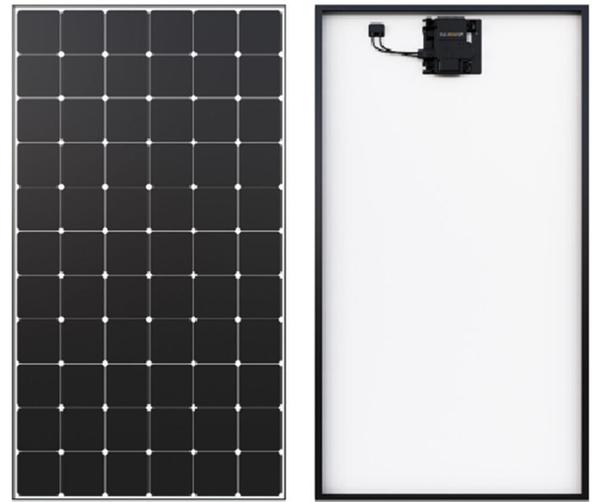
MAXEON SOLAR TECHNOLOGIES, LTD.
                                                                                                                                                               537620 Rev.D

Maxeon Solar Technologies recommends a conservative minimum cable bend                            Limits may vary. Refer to local requirements to define the number of
radius of equal to or greater than 60mm and must not be bent on the direct exit                   microinverters per branch in your area.
of the connector or junction box. The AC Module cable system features locking
connectors which, after connected, require the use of a tool to disconnect. This                      CAUTION! To reduce the risk of fire, connect only to a
defends against untrained personnel disconnecting the modules when under
                                                                                                       circuit provided with 20 A maximum branch circuit
load. Enphase AC cable connectors are rated and tested to interrupt load current;
however, Maxeon Solar Technologies recommends that you always open the                                               overcurrent protection.
utility dedicated branch circuit breaker to remove power before plugging or
                                                                                                  Below are the major installation steps:
unplugging any connectors; install an AC isolator in accordance with local codes.
                                                                                                       1. Install the Field‐wireable connector pair, optional J‐Box
                                                                                                       2. Position the Enphase Q Cable
4.1 Equipment Grounding                                                                                Per module:
Module grounding is required as per IEC 60364‐7‐712 and where deemed
                                                                                                                 3      Position AC module and pop‐out microinverters
mandatory within the local regulatory framework. The purpose of the module
                                                                                                                 4      Connect microinverters to Q Cable connector
grounding is both for protection and functional reasons. The functional aspect of
                                                                                                                 5      Install AC Modules
this requirement is to enable the Inverter or power conditioning device to provide
                                                                                                                 6      Manage Q cable to module frame and rail
earth fault detection and any alarm indication. Maxeon Solar Technologies
                                                                                                       Per row:
recommends using one of the following methods of grounding the module frame.
                                                                                                                 7      Create installation map
In addition, to avoid corrosion due to dissimilar metal interfaces, Maxeon Solar
                                                                                                                 8. Terminate Q cable at last microinverter
Technologies recommends stainless steel hardware between copper and
                                                                                                                 9. Connect to J‐Box
aluminum. Testing should be done to validate grounding with temperature, salt
                                                                                                                 10. Energize system
environment and high current.
1)   Grounding using specified grounding holes: Use the mounting frame
                                                                                                  4.3 Cable Management:
     provisioned grounding holes for connecting the module to the racking with
     a suitably sized earthing conductor.                                                         Use cable clips or cable ties wraps to attach the AC cable to the racking. The cable
                                                                                                  must be supported to avoid any cable
2)   Grounding with clamp / claw: Clamp or claw can be installed between the                      undue sag as per local requirement.
     module and racking system. Align a grounding clamp to the frame hole, and
     place a grounding bolt through the grounding clamp and frame. Ensure the                     For Performance 3 AC modules, be careful
     clamp used when is fastened, will effectively pierce the anodized coating of                 to not unplug the DC cable premounted in
     the module and ensure suitable conductivity.                                                 factory into specific cable supports.
                                                                                                  Dress any excess cabling in loops so that it
3)   Modules may be grounded by attaching a lay‐in lug to one of the grounding                    does not contact the roof. Do not form
     holes on the module frame, and attach the ground conductor to the lug. Use                   loops smaller than 12 cm in diameter.
     stainless steel hardware (bolt, washers, and nut). Use an external‐tooth star
     washer between the lug and the module frame in order to pierce the
     anodizing and establish electrical contact with the aluminum frame. The
     assembly must end with a nut that’s torqued to 2.3‐2.8 Nm (for a M4 bolt).                   4.4 Microinverters Connection
     A lock washer or other locking mechanism is required to maintain tension                     Refer to the major installation steps defined in Section4.2and listen for a click:
     between the bolt and the assembly. The conductor must be attached to the                     1) when the microinverters are pop out and
     ground lug using the lug’s set screw.                                                        2) when AC connectors engage
4)   Modules may be grounded using a ground clip or ground washer or as part                      Inspect the AC connectors to ensure that
     of a module clamp. These grounding clips/washers must be able to                             they are not broken, misshapen, or
     effectively pierce the anodized coating of the module frame and establish                    otherwise degraded prior to connection.
     suitable electrical conductivity.                                                            Cover any unused connectors on the AC
                                                                                                  cable with Enphase Sealing Caps. Listen for
All above solutions are possible but should be tested with the mounting structure                 a click as the sealing caps engage.
for grounding purpose.

4.2 Connection to AC Circuits
It is the installer’s responsibility to verify grid compatibility in your installation
region (240/380 or 4‐wire 2‐pole). The AC Modules must be connected to a utility                  CAUTION! Install sealing caps on all unused AC connectors
source at the correct voltage and frequency in order to operate and produce                         as these connectors become live when the system is
power. They are not standalone generators and do not create AC voltage thus are
                                                                                                  energized. Sealing caps are required for protection against
not capable of operation independent of a utility‐generated AC signal. The AC
Modules must be connected only to a dedicated branch circuit. The AC cables and                                        moisture ingress.
connectors are certified and rated for the maximum number of AC units in parallel
only. When connecting modules, DO NOT exceed the following single AC branch                       5.0 Module Mounting
circuit maximum number of modules.
The maximum number of microinverters that can be installed on each AC branch                      This section contains information for AC Modules. Ensure that you use the correct
circuit can be found in the Product's datasheet. This circuit must be protected by                information for your module type.
overcurrent protection. Plan your AC branch circuits to meet the following limits                 The Maxeon Solar Technologies Limited Warranty for PV Modules is contingent
for maximum number of AC Module per branch when protected with a 20 amp                           upon modules being mounted in accordance with the requirements described in
(maximum) over current protection device.                                                         this section.

 Maximum* IQ 7A Micros per            Maximum* IQ 7A Micros per                                   5.1 Site Considerations
 AC branch circuit (240 VAC)          AC branch circuit (230 VAC)                                 AC Module should only be mounted in locations that meet the following
 Region: EU                           Region: APAC                                                requirements:
 10                                   11

                 ©2021 Maxeon Solar Technologies, Ltd. All rights reserved. Specifications included in this document are subject to change without notice.                             4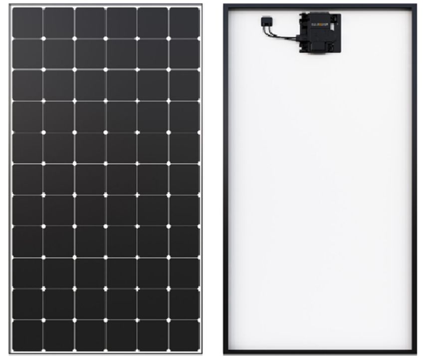
MAXEON SOLAR TECHNOLOGIES, LTD.
                                                                                                                                                                537620 Rev.D

Maximum Altitude: AC Modules can be installed in locations with a maximum                          Fig.1 With Rail Support
of 2000 meter above sea level.
                                                                                                   For Maxeon 5 RES AC:
Operating Temperature: AC Modules must be mounted in environments that
ensure that the modules will operate within the following maximum and
minimum temperatures:
   Max. Operating Cell Temp.                +85°C
   Max. Operating microinverter Temp.       + 60°C
   Max. AC Module Ambient Temp.             +50°C
   Min. AC Module Operating Temp.           −40°C

Design Strength: AC Modules are designed to meet a maximum positive (or
upward, e.g. wind) and negative (or downward, e.g. static load) design pressure
when mounted in the mounting configurations specified in Table 1 and 2 for the
details on load ratings and mounting locations. AC Modules have also been
evaluated to IEC 61215 for a positive or negative design load of 3600 Pa with a
1.5 Safety Factor.

When mounting modules in snow‐prone or high‐wind environments, special care
should be taken to mount the modules in a manner that provides sufficient design
strength while meeting local code requirements.
                                                                                                    For Performance 3 RES AC:
Important! The following image and tables show where to mount in module
frame and the allowable load ratings corresponding to the mounting zones
chosen. To use the tables, identify the two mounting zones in which you wish to
mount. You may choose to mount at any location in zones A, B, and C, as long as
the mounting points are symmetric about one axis of the module. Identify the
combination of mounting zones you have chosen in the table and then refer to
the corresponding load rating. Note also that load ratings are different for
modules supported by rails; versus systems that attach modules underneath the
module frame or without rail support.

Table 1. Design Load Ratings (Tested with FOS=1.5 Safety factor)
                                         Wind (up and down)/ Snow (down)
                                                      (in Pa)
  Mounting       Mounting
  Method          Zone               MAX5 RES AC                       P3 RES AC
                                    Rail
                                            w/o Rail             Rail         w/o Rail
                                 Supporte
                                            Support*          Supported       Support*
                                     d
                                  2700/      2400/              1600/           1600/              Additional Authorized Operating Environments:
                     BB                                                                            Modules can be mounted in the following aggressive environment according to
                                   5400       3600              3600            2400
                                  1700/      1600/              1600/           1600/              the test limits mentioned below:
                     CC                                                                            Salt mist corrosion testing: IEC 61701 Severity 6
                                   1600       1600              3600            2400
                                  1600/      1600/              1600/           1300/              Ammonia Corrosion Resistance: IEC 62716 Concentration: 6,667 ppm
    Top              AA            2400       1600              4000            1600
   Clamp                                                                                           Excluded Operating Environments
                                  1600/      1600/
                     AB            1600       1600
                                                                  NA               NA              Certain operating environments are not recommended for SunPower AC
                                  1600/      1600/                                                 modules, and are excluded from the Maxeon Solar Technologies Limited
                     AC            2400       1600
                                                                  NA               NA              Warranty for these modules. Maxeon’s modules should not be mounted a site
                                                                                                   where it may be subject to direct contact with salt water, or other aggressive
                                                                                1000/
                     EE             NA             NA             NA                               environment. Maxeon’s modules should not be installed near flammable liquids,
                                                                                1600
                                                                                                   gases, or locations with hazardous materials; or moving vehicles of any type.
                                  3600/          3600/
                     BB                                                                            Contact Maxeon Solar Technologies if there are any unanswered questions
                                  6000           3600
                                                                                                   concerning the operating environment.
                                  2800/          2800/
                     CC
                                  2800           2400
                                                                                                   5.2 Mounting Configurations
                                  2000/          2000/
     Bolt            AA                                           NA               NA              Modules may be mounted at, appropriate orientation to maximize sunlight
                                  3000           2000
                                                                                                   exposure.
                                  1700/          1600/
                     AB                                                                            In order to prevent water from entering the junction box (which could present a
                                  2800           1600
                                                                                                   safety hazard), modules should be oriented such that the junction box is in the
                                  2000/          2000/
                     AC                                                                            uppermost position and should not be mounted such that the top surface faces
                                  3000           2000
                                                                                                   downward.
                    DD                            DO NOT MOUNT                                     In addition, ensure the module orientation also prevents the microinverter from
*Without Rail support means end mounted in long or short side frame.                               direct exposure to rain, UV and other harmful weather events (ice/snow).
                                                                                                   We also want to remind that the watertightness is not ensured by the modules
                                                                                                   but by the mounting system and that drainage should be well designed for AC
                                                                                                   modules. Maxeon recommends for a good performance of the system (reduction
                                                                                                   of soiling effect/water pooling) a minimum of 5° tilt angle.

                  ©2021 Maxeon Solar Technologies, Ltd. All rights reserved. Specifications included in this document are subject to change without notice.                     5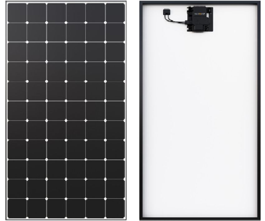
MAXEON SOLAR TECHNOLOGIES, LTD.
537620 Rev.D
Clearance between the module frames and structure or ground is required to surface of a module is sensitive to oils and abrasive surfaces, which may lead to
prevent wiring damage and allows air to circulate behind the module. The scratches and irregular soiling.
recommended assembling clearance between each module installed on any
mounting system is a minimum of 5 mm distance. Be careful not to touch the micro‐inverter while unloading the Performance 3 AC
modules, as the micro‐inverter height exceeds the module frame slightly.
Clearance between the module frame and roof surface is required to prevent
wiring damage and to enable air to circulate behind the module. Therefore a AC Modules are featured with antireflective coated glass and they are prone to
minimum of 50mm is required between the module frame and the roof surface. visible finger print marks if touched on the front glass surface. Maxeon Solar
Technologies recommends handing AC Modules with gloves (no leather gloves)
When installed on a roof, the module shall be mounted according to the local and or limiting touching of the front surface. Any finger print marks resulting from
regional building and fire safety regulations. In case the module is installed in a installation will naturally disappear over time or can be reduced by following the
roof integrated PV‐System (BIPV), it shall be mounted over a watertight and fire‐ washing guidelines in Section 6.0 below. Any module coverage (colored plastic
resistant underlayment rated for such application. tarps or similar) during installation can lead to permanent front glass
discoloration and is not recommended. The use of vacuum lifting pads can cause
For Peformance 3 AC modules, in order to provide better access of connection permanent marks on the front glass.
for AC cables into the microinverter, Maxeon recommends the following Shading incidence need to be avoided during PV system operation. The system is
installation sequence: not supposed to be energized until the mounting scaffolding or railing have been
When the microinverter is in lower position, then it is recommended removed from the roof.
to install the modules from Left to Right.
When the microinverter is in upper position, then it is recommended Systems should be disconnected in any cases of maintenance which can cause
to install the modules from Right to Left. shading (e.g. chimney sweeping, any roof maintenance, antenna/dish
installations, etc.).
Modules mounting systems should only be installed on building that have been
formally considered for structural integrity and confirmed to be capable of 6.0 Maintenance
handling the additional weighted load of the modules and mounting systems, by
Maxeon Solar Technologies recommends visual inspection on a regular basis of
a certified building specialist or engineer.
AC modules for safe electrical connections, sound mechanical connection, and
free from corrosion. This visual inspection should be performed by trained and
AC Modules are only certified for use when their factory frames are fully intact.
licensed personnel. The standard frequency is once a year according to
Do not remove or alter any module frame. Creating additional mounting holes
environmental conditions.
may damage the module and reduce the strength of the frame.
Periodic cleaning of AC Modules is recommended, but is not required. Periodic
Modules may be mounted using the following methods only:
cleaning has resulted in improved module performance, especially in regions with
1) Pressure Clamps or Clips: Force must not deform low levels of annual precipitation (less than 46,3cm (18,25 inches)). Consult
Mount the module with top frame flange or installer supplier about recommended cleaning schedules for your area. Do not
the clips attached to the glass may break Force has
to be
clean or spray modules with water during normal operation (module glass surface
longer sides of the module.
applied in is hot). To clean a module, spray it with potable, non‐heated water. Normal water
Refer to the allowable
line with pressure is more than adequate, but pressurized water 100 bar (min 50 cm
ranges in Section 5.0 (Table frame distance) may be used. Fingerprints, stains, or accumulations of dirt on the front
1 ). Installers must ensure wall surface of the module may be removed as follows: rinse the area and wait 5
the clamps are of sufficient
minutes. Re‐wet the area and then use a soft sponge or seamless cloth to wipe
strength to allow for the
Figure 1a: Clamp Force Locations the glass surface in a circular motion. Fingerprints typically can be removed with
maximum design pressure
a soft cloth or sponge and water after wetting. NEVER use harsh cleaning
of the module. Clips and clamps are not provided by Maxeon Solar
materials such as scouring powder, steel wool, scrapers, blades, or other sharp
Technologies. Clamps that secure to the top of the frame must not deform
instruments to clean module glass. Use of such materials on the modules will void
the top flange. Clamps must apply force collinear with the ‘wall’ of the
the product warranty.
module frame and not only to the top flange. Clamps shall not apply
excessive force to the frame, warp the top flange, or contact the glass ‐
these practices void the module warranty and risk frame and glass Shipping Position:
breakage. Figure 1a illustrates locations for top frame clamp force. Avoid
clamping within 50mm of module corners to reduce risk of frame corner
deflection and glass breakage. When clamping to the module frame, torque
shall never exceed 15 N.m to reduce chances of frame deformation. A
calibrated torque wrench must be used. Mounting systems should be
evaluated for compatibility before installing specially when the system is
not using Clamps or clips. Please contact Maxeon Solar Technologies for the
approval of the use of non‐standard pressure clamps or clips where torque Install Position:
values are higher than otherwise stated.
2) End Mount: End mounting is clipping/clamping of solar modules at the
corner of short side to the supporting rail. The end‐mounting rail and clips
or clamps must be of sufficient strength to allow for the maximum design
pressure of the module. Verify this capacity for both 1) clamps or clips and
2) end mounting system vendor before installation.
5.3 Handling of Modules during Installation
Never lift or move the modules using cables or the junction box under any
circumstances. Do not place modules face forward in direct contact with abrasive 7.0 Troubleshooting
surfaces such as roofs, driveways, wooden pallets, railings, or walls etc. The front Make sure to follow all safety precautions described in this installation manual.
The microinverters are monitored by Enphase Enlighten system. If a module is
©2021 Maxeon Solar Technologies, Ltd. All rights reserved. Specifications included in this document are subject to change without notice. 6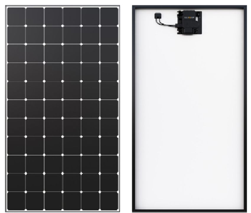
MAXEON SOLAR TECHNOLOGIES, LTD.
537620 Rev.D
found to not produce power through the Enphase Enlighten System, please 8.0 Appendix (Supplementary Technical Information)
contact Enphase as the first point in the trouble shooting process. If Enphase
microinverter is found to be functioning properly, Enphase will contact Maxeon 1. Enphase IQ7 Installation and Operation Manual
Technical Support directly. https://enphase.com/en‐uk/support/enphase‐iq‐7‐iq‐7‐iq‐7x‐microinverter‐
Troubleshooting an inoperative microinverter, please follow the Enphase installation‐and‐operation‐manual
troubleshooting process:
1. Web forms – send an email through https://enphase.com/en‐ 2. Enphase Installer Toolkit Commissioning:
in/support/contact‐support#form https://enphase.com/en‐in/support/gettingstarted/commission
2. Call center Enphase Installer Toolkit is the mobile app where you can view the
Europe microinverter serial numbers and connect to the IQ Envoy to track system
Netherlands: +31‐73‐7041633 installation progress. To download, go to http://www.enphase.com/toolkit and
France/Belgium: +33(0)484350555 log in to your Enlighten account.
Germany: +49 761 887893‐20 Getting Started Guide:
UK: +44 (0)1908 828928 https://enphase.com/sites/default/files/GettingStartedGuide_SystemVerificatio
APAC nUsingInstallerToolkit_InsideSystem.pdf
Melbourne, Australia: +1800 006 374
New Zealand: +09 887 0421 Installation Troubleshooting :
India: +91‐80‐6117‐2500 https://enphase.com/en‐uk/support‐associated‐products/installer‐
toolkit
3. Claiming process through Enlighten for installers:
https://enphase.com/en‐uk/support/system‐owners/troubleshooting 3. Enphase IQ Envoy Installation and Operation Manual:
Refer to the Enphase IQ Envoy Installation and Operation Manual to activate the
All other faults please refer to the Enphase IQ Envoy Installation and Operation system monitoring and grid management functions.
Manual at enphase.com/support for troubleshooting procedures. https://enphase.com/sites/default/files/downloads/support/IQ‐Envoy‐Manual‐
EN‐US.pdf
The guide provides the following:
o Connecting the Envoy
o Detecting devices and scanning the installation map
o Connecting to Enlighten and registering the system
Table 2. Electrical Characteristics and Grid Interaction.
DC Electrical Characteristics:
DC Ratings
DC values @ STC Temperature Efficiency
Curr. at Voltage
Voltage at Open Circuit Curr. (Isc) Power Temp. NOCT @ Nom. Peak power
Nom. Power Rated Short Circuit (Voc) Temp. Module
Model Rated Power Voltage, Voc Temp. Coeff. Coeff. 20°C (value ± (W) per unit area:
Power (W) Tol. (%) Power, Impp Curr., Isc(A) Coeff. Efficiency (%)
(Vmpp) (V) (%/°C) (%/°C) 2°C) m2 / ft2
(A) (%/°C)
SPR‐MAX5‐420‐E3‐AC 420 +5/−0 40.5 10.4 48.2 10.9 0.057 −0.239 −0.29 43 22.5 225/20.9
SPR‐MAX5‐415‐E3‐AC 415 +5/−0 40.3 10.3 48.2 10.9 0.057 −0.239 −0.29 43 22.3 221/20.5
SPR‐MAX5‐410‐E3‐AC 410 +5/−0 40.0 10.2 48.2 10.9 0.057 −0.239 −0.29 43 22.0 220/20.4
SPR‐MAX5‐400‐E3‐AC 400 +5/−0 39.5 10.1 48.1 10.9 0.057 −0.239 −0.29 43 21.5 212/19.7
SPR‐MAX5‐390‐E3‐AC 390 +5/−0 39.0 9.99 48.0 10.8 0.057 −0.239 −0.29 43 20.9 209/19.4
SPR‐P3‐385‐BLK‐E3‐AC 385 +5/−0 36.3 10.61 43.7 11.31 0.06 −0.28 −0.34 45 19.6 196/17.3
SPR‐P3‐380‐BLK‐E3‐AC 380 +5/−0 35.9 10.59 43.4 11.28 0.06 −0.28 −0.34 45 19.4 194/17.1
SPR‐P3‐375‐BLK‐E3‐AC 375 +5/−0 35.5 10.57 43.0 11.26 0.06 −0.28 −0.34 45 19.1 191/16.9
SPR‐P3‐370‐BLK‐E3‐AC 370 +5/−0 35.1 10.55 42.6 11.24 0.06 −0.28 −0.34 45 18.9 189/16.7
AC Electrical Characteristics:
AC Ratings
AC values @ STC Operating Limits
AC Max. Extended AC Short Circuit
AC Max. Max. AC Peak AC Port
AC Voltage Cont. Frequency Fault Current Overvolta Power Power Factor
Cont. Series Output Freq. (nom., Backfeed Max. Units per Branch
Model Output Output Range Over 3 Cycles ge Class Factor (adjustable)
Output Fuse Power Hz) Current (Europe – Australia)
(nom., V) Power, W (Hz) (A rms) AC Port Setting lead. / lag.
Curr. (A) (A) (W) or VA (mA)
or VA
SPR‐MAX5‐420‐E3‐AC 219‐264 1.52 20 349 366 50 45‐55 5.8 III 18 1.0 0.8 / 0.8 10 ‐ 11
SPR‐MAX5‐415‐E3‐AC 219‐264 1.52 20 349 366 50 45‐55 5.8 III 18 1.0 0.8 / 0.8 10 ‐ 11
SPR‐MAX5‐410‐E3‐AC 219‐264 1.52 20 349 366 50 45‐55 5.8 III 18 1.0 0.8 / 0.8 10 ‐11
SPR‐MAX5‐400‐E3‐AC 219‐264 1.52 20 349 366 50 45‐55 5.8 III 18 1.0 0.8 / 0.8 10 ‐ 11
SPR‐MAX5‐390‐E3‐AC 219‐264 1.52 20 349 366 50 45‐55 5.8 III 18 1.0 0.8 / 0.8 10 ‐ 11
SPR‐P3‐385‐BLK‐E3‐AC 219‐264 1.52 20 349 366 50 45‐55 5.8 III 18 1.0 0.8 / 0.8 10 ‐11
SPR‐P3‐380‐BLK‐E3‐AC 219‐264 1.52 20 349 366 50 45‐55 5.8 III 18 1.0 0.8 / 0.8 10 ‐ 11
SPR‐P3‐375‐BLK‐E3‐AC 219‐264 1.52 20 349 366 50 45‐55 5.8 III 18 1.0 0.8 / 0.8 10 ‐ 11
SPR‐P3‐370‐BLK‐E3‐AC 219‐264 1.52 20 349 366 50 45‐55 5.8 III 18 1.0 0.8 / 0.8 10 ‐ 11
Please refer to the module datasheet for the AC electrical characteristic
©2021 Maxeon Solar Technologies, Ltd. All rights reserved. Specifications included in this document are subject to change without notice. 7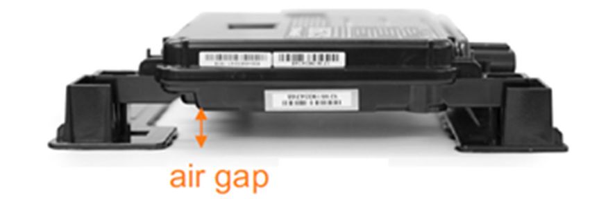
MAXEON SOLAR TECHNOLOGIES, LTD.
                                                                                                                                                               537620 Rev.D

Table 3. Module Frame Details
  Platform                                       Module mounting and ground hole detail                                                                     Frame Profile
                                                     MAX5 RES AC GENERATION 5.2 FRAME MODULES
                                                                                                                                                           SIDE FRAME PROFILE
                                                                                 1835 mm
                                                                                 1645 mm
                                                                                                                                                                                 40

                                                                                                            Ground Holes
                                                                                                                                                                    32
 Residential                                                                                                                                               END FRAME PROFILE
                              1017 mm

 Modules

                                                                                                                                                                                 40

                                                                                                                                                                    24

                                                     P3 RES BLK AC GENERATION 4.3 FRAME MODULES
                                                                              1690 mm                                                                      SIDE FRAME PROFILE
                                                                             1500 mm

                                                                                                                                     35 mm
                                                                             1300 mm
                                                                              1100 mm

                                                                                                                                                           35mm
                                                                                                                                                                         32 mm
 Residential
                                                                                                                                                           END FRAME PROFILE
                                   1160 mm

 Modules
                                                                                                                                                             35mm

                                               4X Ø 4.2mm                                     8X Ø 6.8 mm
                                             Grounding Holes                                 Mounng Holes                                                               24 mm

               ©2021 Maxeon Solar Technologies, Ltd. All rights reserved. Specifications included in this document are subject to change without notice.                              8
NOUVELLE VERSION : D

       Instructions de sécurité et d’installation pour les modules SunPower AC
                 Le contenu du présent document est susceptible d’être modifié sans préavis.

En cas d’incohérence ou de conflit entre la version anglaise et toute autre version de ce manuel (ou document),
                                  la version anglaise prévaudra à tous égards.

                                     Maxeon Solar Technologies, Ltd.
                          sunpower.maxeon.com/fr/ | sunpower.maxeon.com/be/fr

                                                                                                   537620 Rev.D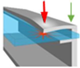
Table des matières
1.0 Introduction................................................................................................................................................................ 3

      1.1 Définitions............................................................................................................................................................................. 3

      1.2 Exclusion de responsabilité .................................................................................................................................................. 3

      1.3 Conformité aux normes de la Commission Électrotechnique Internationale (CEI)) ............................................................. 3

     1.4 Garantie limitée ..................................................................................................................................................................... 3

2.0 Consignes de sécurité ................................................................................................................................................................ 3

3.0 Caractéristiques électriques....................................................................................................................................................... 3

        3.1 Résistance au feu ................................................................................................................................................................ 4

4.0 Branchements électriques ......................................................................................................................................................... 4

        4.1 Mise à la terre ..................................................................................................................................................................... 4

       4.2 Raccordement aux circuits AC ............................................................................................................................................. 4

       4.3 Chemin de câble .................................................................................................................................................................. 4

       4.4 Raccordement des micro‐onduleurs.................................................................................................................................... 5

5.0 Montage des modules ............................................................................................................................................................... 5

      5.1 Considérations relatives au site ............................................................................................................................................ 5

      5.2 Considérations d’installation ................................................................................................................................................ 6

      5.3 Manipulation des modules lors de l’installation................................................................................................................... 7

6.0 Maintenance .............................................................................................................................................................................. 7

7.0 Dépannage ................................................................................................................................................................................. 7

8.0 Annexe (informations techniques complémentaires) ............................................................................................................... 7

Caractéristiques électriques et détails du cadre des modules .......................................................................................................... 8
MAXEON SOLAR TECHNOLOGIES, LTD.
537620 Rev.D
Instructions de sécurité et d’installation pour les
Modules AC 1.4 Garantie limitée
CONSIGNES DE SÉCURITÉ IMPORTANTES Les garanties limitées applicables aux Modules AC sont décrites dans les
conditions de garantie SunPower disponibles à l’adresse
À CONSERVER SOIGNEUSEMENT www.sunpower.maxeon.com/fr/ (se reporter au document de garantie limitée).
FRENCH
1.0 Introduction 2.0 Consignes de sécurité
Avant d’installer cet appareil, lisez toutes les instructions de sécurité contenues
Ce document contient des instructions de sécurité et d’installation dans le présent document.
relatives aux modules photovoltaïques SunPower AC, conformes aux
normes DC et AC (micro‐onduleur) portant les logos TUV et EnTest sur
Danger ! Les interconnexions du Module AC génèrent du courant continu
l’étiquette du produit : (DC) et du courant alternatif (AC) en sortie, et sont sous tension lorsque le
Module AC est raccordé et lorsqu’il est exposé à la lumière. Les courants
électriques peuvent former un arc électrique en cas de coupures et peut être
à l’origine de dommages corporels ou de décès en cas de connexion
ou déconnexion inappropriée, ou en cas de contact avec des composants de
module endommagés.
Débrancher la source AC de tous les Modules AC de l’installation avant
Important ! Veuillez lire ces instructions en entier avant toute de réaliser les connexions électriques et /ou couvrir tous les panneaux de
installation, tout branchement ou toute utilisation du produit. l’installation PV avec un tissu ou un matériau opaque avant de procéder à un
Le non‐respect de ces instructions aura pour effet d’invalider la raccordement ou à une déconnexion électrique du système.
garantie limitée des modules SunPower pour ces modules et /ou la Ne pas connecter ou déconnecter les modules quand un courant est présent
en provenance des modules de la chaine ou d’une source extérieure.
garantie limitée des micro‐onduleurs Enphase Energy.
Pour les connecteurs accessibles à des personnes non qualifiées, il est
impératif d’utiliser les connecteurs verrouillables, si applicable, afin d’interdire
1.1 Définitions aux personnes non qualifiées de pouvoir déconnecter les Modules AC une fois
Module AC : module Maxeon 5 AC et Perfomance 3 AC qu’ils ont été installés.
Module DC: un module photovoltaïque standard sans micro‐onduleur. Toutes les installations doivent être réalisées en conformité avec l’ensemble
Micro‐onduleur Enphase : le micro‐onduleur IQ 7A, compatible avec les réseaux des règlementations en vigueur.
intelligents, convertit le courant DC (courant continu) du module photovoltaïque Seuls les personnels qualifiés sont autorisés à effectuer l’installation.
en courant AC (courant alternatif) conformément au réseau. Avant d’installer ce produit, ôter tout bijou métallique, afin de limiter les
Câble AC Enphase : également appelé Q Cable, il s’agit d’un câble AC d’une risques d’exposition accidentelle à des circuits électriques sous tension.
longueur comprise entre 1,3 m et 2,3 m selon la disposition du Module AC Utiliser des outils isolés pour réduire le risque de choc électrique.
(portrait ou paysage), de 2,5 mm² de section, avec double isolation, utilisable en
Ne pas se tenir debout ou marcher sur les Modules AC, ni les laisser tomber,
extérieur et avec connecteurs intégrés pour micro‐onduleurs. Maxeon Solar
ni les érafler ou les rayer ; éviter toute chute d’objet sur le verre.
Technologies recommande l’utilisation d’un câble Q‐Cable d’une longueur de
2,0m pour plus de flexibilité lors de l’installation en mode portrait. Le module AC Si le module est endommagé (verre brisé, boîtes de jonction endommagées,
se branche directement sur le câble Q qui comprend des connecteurs intégrés en connecteurs cassés et/ou couche arrière endommagée), tout contact avec
usine. la surface ou le cadre du module présente des risques électriques ou de
Enphase Enlighten : logiciel Web de surveillance et de gestion. Les installateurs lacération. Si un module est fissuré après son installation, un technicien
peuvent utiliser Enlighten Manager pour consulter des données détaillées sur les qualifié doit le retirer et contacter le fournisseur pour obtenir des instructions
performances, gérer plusieurs installations photovoltaïques, etc. relatives à son enlèvement.
Connecteur DC: Maxeon Solar Technologies recommande d’utiliser la même Ne pas installer ou manipuler les Modules AC lorsque ceux‐ci sont humides,
marque de connecteur pour votre installation PV. Le connecteur validé est de type ou en cas de vent fort.
Tyco Electronics PV4S. Les connecteurs non connectés doivent toujours être protégés contre toute
contamination (par exemple : poussière, humidité, particules étrangères, etc.)
1.2 Exclusion de responsabilité avant et pendant l’installation. Ne pas laisser les connecteurs non connectés
Les techniques d’installation, de manutention et d’utilisation de ce produit sont (non protégés) exposés aux conditions ambiantes. Un environnement propre
hors du contrôle de la société. Par conséquent, Maxeon Solar Technologies rejette d’installation est essentiel pour éviter une dégradation des performances.
toute responsabilité en cas de perte, de dommages ou de frais résultant d’une Ne pas obstruer les trous de drainage ou laisser l’eau s’accumuler à l’intérieur
installation, d’une manipulation ou d’une utilisation incorrecte. ou autour des cadres des Modules AC.
Si une intervention de maintenance est nécessaire, contacter le fournisseur du
1.3 Conformité aux normes de la Commission Électrotechnique module.
Internationale (CEI) Conserver ces instructions !
Ce produit vise à respecter ou dépasser les exigences stipulées dans la norme
CEI 62109‐3 pour les SunPower modules AC. La norme CEI 62109‐3 concerne les 3.0 Caractéristiques électriques
modules photovoltaïques destinés à être installés sur des bâtiments ou de façon
Les caractéristiques électriques et les données d’interaction avec le réseau
autonome. La certification TUV n’inclut pas l’intégration à la façade d’un bâtiment,
figurent au tableau 2 et dans la fiche technique du Module AC. Il incombe à
car des exigences supplémentaires peuvent s’appliquer. Ce produit n’est pas
l’installateur de définir le profil du réseau et de vérifier sa conformité par rapport
destiné à être utilisé dans les applications où le rayonnement solaire est
à la configuration initiale d’Enphase dans le pays d’installation. Cette opération
artificiellement concentré sur le module.
n’est possible qu’en accédant à Internet et en se connectant au système Enphase
Enlighten.
Ce manuel doit être utilisé en combinaison avec les meilleures pratiques
reconnues par l'industrie. Les Modules AC SunPower doivent être installés
uniquement par des professionnels certifiés.
©2021 Maxeon Solar Technologies, Ltd. Alle Rechte vorbehalten. Wir behalten uns eine kurzfristige Änderung der in diesem Dokument aufgeführten Spezifikationen vor. 3MAXEON SOLAR TECHNOLOGIES, LTD.
537620 Rev.D
Si une installation comporte un Module AC qui ne figure pas dans cette liste, Le conducteur doit être relié à la cosse de mise à la terre à l’aide d’une vis
consultez l’étiquette du produit à l’arrière du module ou rendez‐vous sur de blocage.
www.sunpower.maxeon.com/fr/ pour télécharger la fiche technique.
4) Mise à la terre au travers d’une bride de serrage intégrant un pointeau ou
Pour rappel sur les modules DC: un module photovoltaïque peut produire plus de une rondelle « éventail ». Cette bride/rondelle de mise à la terre doit être
courant et/ou de tension qu’indiqué pour des Conditions d'essai standard (STC). capable de percer la couche anodisée du cadre du module afin d’établir une
Des conditions météorologiques ensoleillées, des températures basses et le reflet conductivité électrique adéquate.
de la neige ou de l'eau peuvent accroître le courant et la puissance produite. Par Différentes solutions sont possibles pour la mise à la terre, mais elles doivent être
conséquent, les valeurs de courant de court‐circuit (ISC) et de tension de circuit testées avec la structure de montage.
ouvert (VOC) figurant sur le module doivent être multipliées par un facteur de 1,25
pour déterminer la tension nominale des composants, l’intensité admissible des 4.2 Raccordement aux circuits AC
conducteurs, les calibres des fusibles et celles des protections connectées au Il est de la responsabilité de l'installateur de vérifier la compatibilité du réseau
système PV. Un multiplicateur supplémentaire de 1,25 peut être exigé par dans votre région d'installation (240/380 V ou monophasé/triphasé). Les Modules
certaines réglementations pour la détermination du calibre des fusibles et de la AC doivent être raccordés à une source d’alimentation présentant une tension et
section des conducteurs. une fréquence conformes aux spécifications du produit pour permettre leur bon
fonctionnement et la production d’énergie. En effet, n’étant pas des générateurs
3.1 Résistance au feu autonomes et ne créant pas de tension AC, ils ne peuvent pas fonctionner
Le Module AC présente la même résistance au feu de que les modules DC indépendamment d’un signal AC généré par le réseau. Les Modules AC doivent
(courant continu). être branchés uniquement sur un circuit en dérivation dédié. Les câbles et les
connecteurs AC sont certifiés et homologués pour un nombre maximal de
Modules AC connectés en parallèle uniquement. Lors du branchement des
4.0 Branchements électriques
Modules AC, NE PAS DÉPASSER le nombre maximal de Modules AC par circuit AC
Les Modules AC doivent être branchés à l’aide du câble AC Enphase approprié en dérivation.
et des connecteurs intégrés. Ne pas modifier les connecteurs. Le nombre maximal de micro‐onduleurs pouvant être installés sur chaque circuit
Maxeon Solar Technologies recommande que le câble respecte un rayon de AC en dérivation est indiqué dans la fiche technique du produit. Ce circuit doit être
courbure minimal supérieur ou égal à 60 mm et ne soit pas plié juste après le protégé contre les surintensités. Planifier vos circuits AC en dérivation pour qu’ils
connecteur ou la boîte de jonction. Les câbles du Module AC comportent des respectent les limites maximales du nombre de Modules AC avec un dispositif de
connecteurs verrouillables qui, une fois connectés, nécessitent d’utiliser un outil protection de 20 ampères (au maximum).
pour être déconnectés. Ce dispositif permet d’éviter que des personnes non
qualifiées déconnectent les Modules AC lorsque ceux‐ci sont sous tension. Les Nombre maximal* de micro‐ Nombre maximal* de micro‐
connecteurs des câbles AC Enphase sont certifiés et testés pour couper le courant onduleurs IQ 7A par circuit onduleurs IQ 7A par circuit
en charge. Toutefois, Maxeon Solar Technologies recommande de toujours ouvrir AC en dérivation (240 VAC) AC en dérivation (230 VAC)
le dispositif de protection du circuit dédié à l’installation pour couper le courant Région : UE Région : ASIE‐PACIFIQUE
avant de brancher ou débrancher des connecteurs. Installez un sectionneur/ 10 11
disjoncteur AC conformément à la réglementation en vigueur.
4.1 Mise à la terre Reportez‐vous à la réglementation locale en vigueur pour déterminer le nombre
La mise à la terre du module est requise selon la norme CEI 60364‐7‐712 et dans de micro‐onduleurs par dérivation dans votre région, car ce nombre peut varier.
les cas jugés obligatoires (se reporter aux règlementations locales en vigueur).
La mise à la terre répond à la fois à des exigences de protection et de ATTENTION ! Pour réduire le risque d’incendie, procédez au
fonctionnalité. En termes fonctionnels, il s’agit de permettre à l’onduleur ou au raccordement uniquement sur un circuit électrique équipé
matériel de traitement de la puissance de détecter les défauts à la terre et de les
signaler par une alarme. Maxeon Solar Technologies recommande d’utiliser l’une d’une protection contre les surintensités de 20 A
des méthodes ci‐dessous pour la mise à la terre du cadre du module. Et pour éviter au maximum.
toute corrosion due à l’utilisation de métaux de nature différente, Maxeon Solar
Technologies recommande d’utiliser un métal intermédiaire de type acier Ci‐dessous les principales étapes d’installation :
inoxydable entre le cuivre et l’aluminium. Des tests devront être réalisés pour
valider la mise à la terre en fonction de la température, d’un environnement salin 1. Sertir la paire de connecteurs confectionnables (mâle/femelle) ou
et d’un courant élevé. préparer la boîte de jonction (optionnel).
2. Mettre en place le câble Enphase Q Cable
1) Mise à la terre à l’aide des trous prévus à cet effet : utiliser les trous de mise Par module:
à la terre présents sur le cadre du module pour connecter le module au 3. Positionner les modules AC et tirer le micro‐onduleur
support avec un conducteur de terre de section appropriée. derrière le panneau
4. Connecter les micro‐onduleurs au connecteurs Q Cable
2) Mise à la terre au travers des attaches ou brides de serrage : les attaches ou 5. Installer les modules AC
brides de serrage peuvent être installées entre le module et le support. 6. Gérer le câble vis‐à‐vis du cadre du module et de la
Aligner les brides sur le trou du cadre et faire passer une vis de mise à la terre structure de montage.
à travers la bride et le cadre. Vérifier qu’une fois serrée, la bride utilisée Par rangée:
percera la couche anodisée du module pour garantir une conductivité 7. Créer le plan d’installation du champ PV
électrique adéquate. 8. Installer l’embout de terminaison après le dernier micro‐onduleur.
9. Connecter à la boîte de jonction.
3) Mise à la terre en fixant une cosse ouverte à l’un des trous de mise à la 10. Mettre sous tension
terre du cadre du module, puis en fixant un conducteur de terre à celle‐ci.
Utiliser des composants en acier inoxydable (vis, rondelles et écrou).
4.3 Chemin de câble :
Utiliser une rondelle « éventail » à dentures extérieures entre la cosse et
le cadre du module de façon à percer la couche anodisée et établir une Utilisez des serre‐câbles pour attacher le câble AC à la structure de montage. Le
conductivité électrique avec le cadre en aluminium. L’assemblage doit se câble doit être soutenu pour éviter tout affaissement excessif du câble
terminer avec un couple de serrage de 2,3–2,8 Nm sur l’écrou (pour une conformément aux exigences locales.
vis M4). Une rondelle de sécurité ou un autre mécanisme de verrouillage Pour les modules AC Performance 3, veuillez ne pas déconnecter le câble DC
est nécessaire pour maintenir la tension entre la vis et l’assemblage. préassemblé en usine dans des serre‐câbles spécifiques.
©2021 Maxeon Solar Technologies, Ltd. Alle Rechte vorbehalten. Wir behalten uns eine kurzfristige Änderung der in diesem Dokument aufgeführten Spezifikationen vor. 4You can also read