Design, Operation and Maintenance Manual for Membrane Bioreactors applying IPCÒ Membrane Technology - Version 5.0 - June 2020 - Inaqua
←
→
Page content transcription
If your browser does not render page correctly, please read the page content below
Design, Operation and Maintenance Manual
                   for Membrane Bioreactors applying
                       IPCÒ Membrane Technology

Version 5.0 – June 2020
Preface
This manual, published by Blue Foot Membranes N.V., introduces general design and operational
procedures for membrane bioreactors (MBRs) applying IPCÒ membrane module technology by its
clients. Besides safety regulations and general procedures for IPC® module technology, basic design
concepts about membrane bioreactors are described.
Non-observance of the instructions regarding the use, operation and handling of IPCÒ membrane
modules can lead to expiration of warranty.
Detailed operation is presented in the document “General guidelines for the correct use of IPCÒ
Membrane modules”.
In individual cases, a specific addendum to the “General guidelines for the correct use of IPCÒ
Membrane modules” is added as agreed upon with clients.
This manual does not substitute a personal instruction by specialists and operational staff.

 In this manual the following security symbol will be used:

 This symbol highlights that, in case of non-observance of the safety instructions, risks arise which
 may severely endanger/injure service staff, damage or destruct the membrane module or lead to
 environmental pollution.

In case of questions or problems concerning the IPC® technology provided by Blue Foot Membranes
N.V., please contact; Blue Foot Membrane N.V. / Gerard Mercatorstraat 31 / B-3920 Lommel,
Belgium / Email: info@bluefootmembranes.com

                                            Page 2 of 53
Table of contents

1          Integrated Permeate Channel (IPCÒ) Membrane Module ........................................... 6

    1.1 IPCÒ membrane .......................................................................................................................... 6

    1.2 IPCÒ filtration module description ............................................................................................. 7

    1.3 Single-deck modules for MBR applications ................................................................................ 8

    1.4 Multi-deck modules for MBR applications ................................................................................. 9

2          Safety instructions....................................................................................................... 10

    2.1 Personal Health & Safety.......................................................................................................... 11

    2.2 Module Safety .......................................................................................................................... 11

    2.3 Operational Safety ................................................................................................................... 12

    2.4 Environment ............................................................................................................................. 12

3          Basics of membrane bioreactors operation ................................................................ 13

    3.1 Basics of the biological wastewater treatment ........................................................................ 13

    3.2 Operational parameters for MBR ............................................................................................. 13

    3.3 Design parameters and MBR process configuration ................................................................ 14

       3.3.1           Design Parameters .............................................................................................................14

       3.3.2           Configuration of biological reactor.....................................................................................15

       3.3.3           Solids and hydraulic retention times ..................................................................................15

       3.3.4           Mixed liquor suspended solids ...........................................................................................15

       3.3.5           Return activated sludge recirculation ................................................................................16

    3.4 Membrane feed-water quality and pre-treatment .................................................................. 16

       3.4.1           Racks and screen ................................................................................................................17

       3.4.2           Grit and grease removal .....................................................................................................17

       3.4.3           Toxicity ...............................................................................................................................17

       3.4.4           Flow equalization ...............................................................................................................18

                                                                     Page 3 of 53
3.5 MBR operation cycle and cleaning strategies .......................................................................... 18

        3.5.1          Introduction .......................................................................................................................18

        3.5.2          Filtration cycle - Theory ......................................................................................................19

        3.5.3          Operational flux ..................................................................................................................20

        3.5.4          Physical cleaning ................................................................................................................21

            3.5.4.1         Aeration ............................................................................................................................... 21

            3.5.4.2         Backwash ............................................................................................................................. 21

        3.5.5          Chemical cleaning...............................................................................................................21

            3.5.5.1         Maintenance-cleaning or Chemically enhanced Backwash (CEB) ....................................... 21

            3.5.5.2         Recovery-cleaning / Cleaning in Place (CIP)......................................................................... 22

            3.5.5.3         External cleaning ................................................................................................................. 23

            3.5.5.4         Resistance to cleaning chemicals......................................................................................... 24

4          Arrangement of the IPC® modules in a filtration reactor ............................................ 25

    4.1 Arrangement and construction of the modules ....................................................................... 25

    4.2 IPC® module positioning in the membrane tank ...................................................................... 26

    4.3 Pumping technology of the filtration unit ................................................................................ 27

    4.4 De-venting ................................................................................................................................ 27

    4.5 Aeration .................................................................................................................................... 27

5          Handling and preparation of IPC® membrane modules............................................... 28

    5.1 Special precautions for storage and handling of the IPC® Membrane modules ....................... 28

    5.2 Unpacking of the new IPC® Membrane modules ..................................................................... 28

    5.3 Assembly of module towers ..................................................................................................... 30

6          Installation of IPC® Membrane modules ..................................................................... 32

    6.1 Installation in an empty tank.................................................................................................... 32

    6.2 Installation in a filled tank ........................................................................................................ 33

7          Commissioning ............................................................................................................ 35

                                                                       Page 4 of 53
7.1 Step 1: washing out of the glycerine ........................................................................................ 35

    7.2 Step 2: activation of the membrane module ........................................................................... 35

    7.3 Start-up sequence of the membrane unit ................................................................................ 36

    7.4 Shutdown ................................................................................................................................. 36

       7.4.1           Disassembly of the modules...............................................................................................36

       7.4.2           Rinsing of dismounted modules .........................................................................................37

       7.4.3           Conservation of dismounted modules ...............................................................................37

    7.5 Storage of dismounted modules .............................................................................................. 37

       7.5.1           New modules......................................................................................................................37

       7.5.2           Used modules .....................................................................................................................38

       7.5.3           The disposal of old modules ...............................................................................................38

8          Approved chemicals .................................................................................................... 39

    8.1 Manufacturer’s declaration...................................................................................................... 40

    8.2 List of substances damaging the membrane ............................................................................ 41

9          Follow-up during normal operation ............................................................................ 43

    9.1 Process measuring and control technology ............................................................................. 43

    9.2 Service and cleaning procedures .............................................................................................. 44

    9.3 Replacing the aeration elements ............................................................................................. 44

    9.4 Monitoring ............................................................................................................................... 45

10         Annex .......................................................................................................................... 47

    10.1 MBR Nomenclature .................................................................................................................. 47

    10.2 Parameters for characterisation of the wastewater ................................................................ 50

    10.3 Calculation of Transmembrane Pressure ................................................................................. 53

                                                                   Page 5 of 53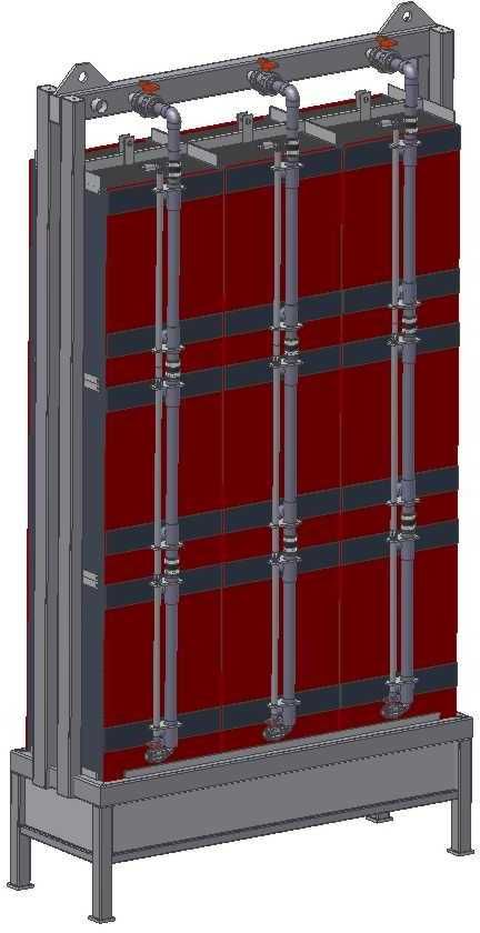
1        Integrated Permeate Channel (IPCÒ) Membrane Module

1.1      IPCÒ membrane
The individual membrane envelopes are comprised of a 3D spacer fabric and coated with a PVDF
membrane on both sides (Figure 1).

                              Figure 1: IPC®-membrane envelope
                                Table 1: IPC®-membrane data

                                        Page 6 of 53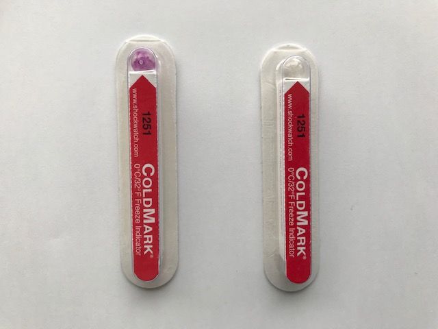
1.2          IPCÒ filtration module description
      The IPC®-membrane modules (
      ) are flat sheet membrane modules, which are constructed by many parallel-arranged membrane
      envelopes with defined distances between these envelopes. The envelopes are fixed within side-
      headers, in which the filtrate of the individual envelopes is collected and discharged.

             buoyancy security                                         permeate outlet
          1.Buoyancy security                                          9. Filtrate Outlet
                                                                       Connection to the collector line
                     guide tube                                           air inlet
                   2.Guide rail
                                                                       10. Air Inlet

            lifting module
                3. Lifting device

           filtration module
           4. Filtration module

              5. Filtration pipe
                 brackets
6. Connection plates /brackets
               aeration unit
          7. Aeration Channel

                  8. Ball valve

                                    Figure 2:      IPC®-membrane module
      1. Buoyancy security          Avoids lifting of the modules during installation, they are filled with air
                                    originally.
      2. Guide rail                 Guides the module in place
      3. Lifting device             Enables loading and un-loading of the modules in the filtration basin using a
                                    hoist or crane
      4. Filtration module          Submerged ultrafiltration membrane module
      5. Filtration pipe            Permeate collection pipe
      6. Connection plates          Holds the aeration device and the module connected (using screws)
      7. Aeration unit              Fine bubble aerator device
      8. Ball Valve                 blind of for single module design or connect permeate line when using stacks
      9. Permeate outlet            Connection to the permeate collector line
      10. Air inlet                 Supply of air to the aeration system

                                                        Page 7 of 53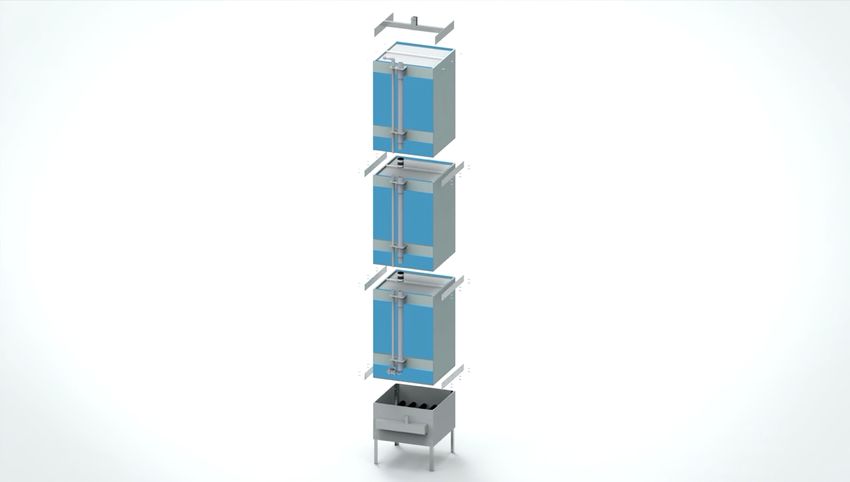
1.3           Single-deck modules for MBR applications
Table 2: Single-deck modules for MBR applications

Module Type                                          IPC® - 7    IPC® - 25    IPC® - 75      IPC® - 80   IPC® - 90

Operating data
Operating pressure                       mbar                                  20 - 350
Temperature range                            °C                                 5 - 50
Backwash pressure                        mbar                                   < 1000

Membrane Data
Membrane material                                                               PVDF
Nominal pore Size                         µm                                     0,04
Maximum pore size**                       µm                                     0,08
                                         2
Average Permeability                   l/m *h*bar                               1.500
                                              2
Flux rate, activated Sludge              l/m *h                                 15 - 50
Concentration, activated sludge MLSS      g/l                                   8 - 15

Module Data                                          IPC® - 7    IPC® - 25    IPC® - 75      IPC® - 80   IPC® - 90
                                              2
Brut Membrane Surface                     m             7           25            75            80          90
                                              2
Net Membrane surface                      m            6,8          23            70            75          85
Membrane plate distance                   mm            9            9            9              8           7
Number of membrane sheets                               12          28            54            59          65
Module material                                                               PUR , PVC

Module Dimensions                                    IPC® - 7    IPC® - 25    IPC® - 75      IPC® - 80   IPC® - 90
Width                                    mm            185          385          736            736         736
Height                                    mm          1090         1058          1070          1070        1070
Height with aeration Channel              mm          1510         1748          1810          1810        1810
Depth                                     mm           316          466          716            716         716
Depth with filtration pipe               mm            343          562          825            825         825
Weight, dry                                  Kg         30          45           130            140         150
Weight, wet (estimate)                       Kg         65          90           280            280         280
permeate connections                                    2            2            2              2           2
Filtration pipe diameter                  DN            15          20            50            50          50

Aeration
Design                                                                       Tube diffuser
Number tubes                                            1            3            5              5           5
Material                                                                       Silicone
                                              3
Aeration demand / module                 Nm /h         4,8          16            48            48          48

* estimater out of Porometer data
** measured by Porometer

                                                  Page 8 of 53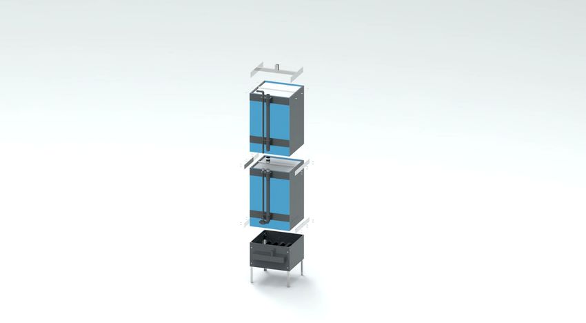
1.4         Multi-deck modules for MBR applications
Table 3: Multi-deck modules for MBR applications based on IPC®-80 module

                                        Double deck                      Multi- deck                Multi deck

                                                                         IPC®-80-003               IPC-80®-003
               Module type                  ®
                                         IPC -80-002
                                                                       MM-3-1-z-001                 MM-5-2-z

                                                     Module data

      Membrane material                                                       PVDF

      Membrane surface                                             Z=1      Z=2        Z=3   Z=1             Z=2
                               [m²]         160
         (approx. data)                                            240      480        720   800             1600

       Material module                                                     PUR, PVC, PP

           Grouting                                                          Plastics

        Module housing                                              Protective plates PVC

                                        Double deck                      Multi- deck                Multi deck

                                                                         IPC®-80-003               IPC-80®-003
               Module type               IPC®-80-002
                                                                       MM-3-1-z-001                 MM-5-2-z

          Dimensions

            Width              [mm]         736                             2425                      3710

                                                                   Z=1      Z=2        Z=3    Z=1                Z=2
            Height             [mm]         2140
                                                                 1070       2140     3210    1070              2140

      Height with aeration
                               [mm]         2880                 2350       3420     4490    2350              3420
            channel

             Depth             [mm]         716                             716                       1432

  Depth with filtration pipe   [mm]         825                             825                       1650

                                                                   Z=1      Z=2        Z=3    Z=1                Z=2
         Weight, dry1)         [kg]         280
                                                                   480      960      1480    1600              3200

      Weight, filled/wet1)     [kg]         560                  1500       3000     4500    5000            10000

         # connections                          4                  6         12         18    20                 40

   Filtration pipe diameter    [DN]             50                           50                        50

                                                      Aeration

            Design                                                         Tube diffuser

            # tubes                             5                            15                        50

                                                 Page 9 of 53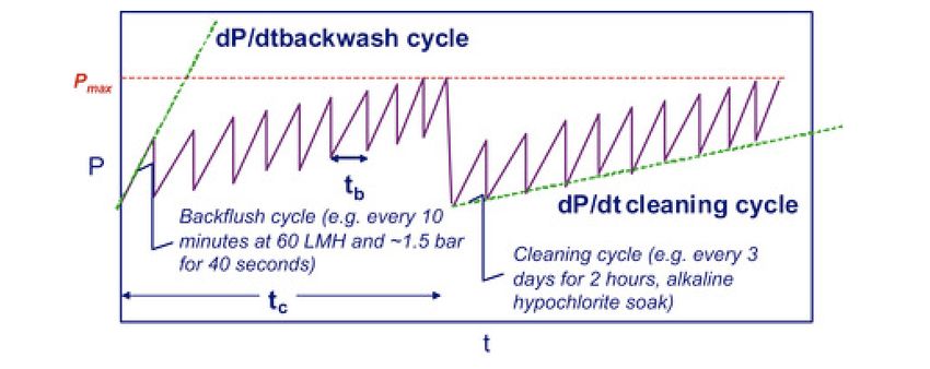
Material                                                 Silicone

         Aeration demand /
                                  [Nm³/h]         48             144   144    144       480         480
              module

    Aeration bubble size                                         medium-sized bubbles

                                                       Picture

    1)
         Weight without aeration unit

2             Safety instructions

                     The security installations, which were installed at the machine by the manufacturer,
                     are just the base of the industrial safety. The main responsibility to guarantee an
                     accident-free operation has to be taken on by the operator and its trained staff.

                     Only proper and intended handling and the compliance with the requested
                     maintenance procedures can guarantee the functionality and a long lifecycle of the
                     membrane modules and of all the parts of the installation. Moreover, proper and
                     intended handling will help to avoid any industrial accident.

                     The staff performing the operation and the maintenance of the filtration plant has to
                     have read and understood this manual. All the instructions mentioned in this manual
                     should be followed together with the document “General guidelines for correct use
                     of IPC membranes in MBR applications”. In particular cases, a project specific
                     addendum is added to the above document as part of the commercial agreement. In
                     this case the guidelines in the addendum overrule the “general guidelines”.

                     In order to guarantee a high system security and to avoid any industrial accidents, only
                     authorized and well-trained staff should be instructed in handling the installation. A
                     technical briefing of potential risks which may occur during the operation of the
                     installation should have been given to the staff.

                                                  Page 10 of 53
The manufacturer will not be liable for personal injuries resp. material damage caused
by improper handling or by non-observance of the mentioned security advices. This
risk will only be covered by the owner resp. the operator of the installation.
An operation of the membrane modules, varying of the hints mentioned in this
manual, will cause the loss of any warranty right.
Please always consider: Safety first!
2.1 Personal Health & Safety
• For any type of equipment used during installation, operation or maintenance on the modules,
ensure personnel are qualified and trained to operate the equipment.
• Keep the working space around the MBR clean and clear at all times; good housekeeping will
prevent injury from slipping and falling.
• When modules are installed, take proper precautions for working at heights.
• Modules may be heavy. Take proper precautions (e.g., safety boots...) to prevent injuries.
• When working with chemicals, always wear safety glasses/goggles and gloves.
• When working with chemicals, ensure to be familiar with the Material Safety Data Sheets (MSDS)
of the chemicals in use at the site.
• Do not mix incompatible chemicals that may lead to formation of hazardous or lethal gases (e.g.
chlorine gas).
• Watch out for mixing of Alkaline and Acid mixing solutions
2.2 Module Safety
• Avoid working with sharp tools, extreme care must be taken not to expose membrane case to
welder or grinder sparks.
• Make 100 % sure that the filtration tank does NOT contain contaminants or sharp-edged items,
like cable slips, swarf or wires.
• Ensure that no materials can fall into the top of the membrane module during installation, it is
strongly recommended to leave a part of the plastic protective packaging over the module during
the module installation in an empty tank until the tank gets filled.
• Move the module only by using the lifting device. NEVER use the filtration pipe as a carrying
handle!
• The module must not be installed by use of force! Avoid any kind of blows affecting the module,
e.g. hammer blows!
• The module must be protected against unintended fall during the installation process!
Multimodules must be protected against toppling.
• When moving a multimodule, a cross beam has to be used. The fastening of a multimodule using
chains and belts is expressly prohibited!
• The dipping and immersion of the modules must be carried out with open collector line with
direct connection to the atmosphere in order to guarantee the captured air to be exhausted!
• The modules must be fixed in the tank against buoyancy using a buoyancy security rail!
Page 11 of 53• The module must be SMOOTHLY lifted out of the water in order to allow the modules to
discharge during this lifting procedure.
• The modules have to be stored in a proper way and drying has to be avoided. Drying of the
membrane surface can destroy the module.
• When lifting IPC® modules outside of the membrane tank, be aware that the wet weight of the
modules will be double the dry weight mentioned in the product specification in case the
membrane channels are filled with sludge.
2.3 Operational Safety
• The membrane surface must not be cleaned by hand or with sharp or abrasive active items! Do
not use a high-pressure waterjet for the cleaning procedure as this damages the membrane
surface!
• Keep membranes wet at all times after first time of use. Irreversible damage may occur if
membranes dry out.
• When preparing cleaning solutions, ensure that all chemicals are dissolved and well-mixed with
the filtrate before backwash of the membranes.
• For chemical cleaning of element, it is important to select the suitable chemicals in accordance
with the type of adherent contaminant. Using the wrong chemicals may cause poorer filtration
performance or damage the element.
• When backwashing with cleaning solutions, note the allowable temperature and pH limits.
• Ensure sufficient de-aeration of the filtrate pipe when backwashing the membranes, to prevent
air entrapment in the membranes.
2.4 Environment
• Disposal of cleaning chemicals should comply with local regulations and best practices.
• If due to operational reasons, the usage of hazardous material is necessary, please respect the
requests of the national / local directives.
Page 12 of 533 Basics of membrane bioreactors operation
3.1 Basics of the biological wastewater treatment
The common attribute of all types of biological wastewater treatments is the degradation of the solids
caused exclusively by the metabolism activity of the micro-organism. During this biological reduction
process, the micro-organisms oxidise the solids. Besides the biomass production (cell growth) by the
metabolism, biomass gases (e.g. elementary nitrogen) which will exit to the atmosphere will be
produced. Therefore, in wastewater treatment plants there are operated aerated and non-aerated
reactors which will eliminate the nitrogen (nitrification and denitrification) and carbon.
The membrane bioreactor (MBR) is a combination of the activated sludge process and the membrane
technology; After the biological degradation process, the biomass (activated sludge) is not isolated by
the conventional sedimentation process in the clarifier, but by a porous membrane filtration. Due to
the small pore size, the membrane is not only a barrier for the activated sludge, but also for suspended
substances and bacteria. Small species like dissolved or colloidal organics and viruses will be adsorbed
on the particulate matter outside of the membrane and as such are excluded significantly from the
filtered water. As a result, a high quality of the effluent is produced.
Parameters for the characterisation of wastewater are presented in Annex 1.
3.2 Operational parameters for MBR
The operation conditions of the IPC® membrane bioreactor modules are provided in Table 4. For
exceptional feedwater quality and applications, please consult Blue Foot Membranes N.V.
Operational Parameter Unit Value
Temperature range: ºC (ºF) 5 – 50 (41–122)
Typical Filtration Trans Membrane Pressure: mbar (psi) 20 – 500 (< 0.29 – 7.25)
Maximum Backwash Trans Membrane Pressure: mbar (psi) 1000 (14.5)
pH range during normal operation — 5–9
Allowable pH range (for cleaning): — 2 – 11 (Max 30°C)
Typical Mixed Liquor Suspended Solids
concentration range: mg/L 8,000–15,000
Flux range l/(m2.h) (gal/(ft2.d)) 10–50 (6–30)
Maximum peak flux / Maximum Backwash flux l/(m2.h) (gal/(ft2.d)) 100 (60)
Air demand / Module or stack (IPC 80) Nm3/h 48
Table 4: Standard operating conditions of the IPC® membrane bioreactor modules
Page 13 of 533.3 Design parameters and MBR process configuration
3.3.1 Design Parameters
The following characteristics should be taken into account for the correct sizing of an MBR design;
Capacity
The amount of permeate water produced for the system (Q, in m3/day).
Peaking Capacity
Peak amount of permeate water produced for the system (Qpeak, in m3/day).
Dissolved Oxygen
The amount of Oxygen that is dissolved in the system and available for biodegration. The membrane
tank of the MBR should have a minimum of 1 ppm dissolved oxygen in order to be in a good operation
condition.
Food to micro-organism ratio
The F/M ratio is a process parameter commonly used to characterize the operating conditions and
presents the BOD F/M in g substrate / g biomass. It is defined as the rate at which the solids are fed
into the tank compared to the mass of the reactor solids (in 1/T), typical values are 0,05-0,2 Max.
Hydraulic retention time
The HRT is the time average residence time of liquid in a tank; the volume of the tank / by the
volumetric flowrate in hours. Typical HRT values for MBR are typically >3-5 hours, where 3 hours is a
minimum.
Return activated sludge
The RAS is the return flow from the membrane tank to the aeration basin of an MBR. In some design
it might be returned to the aerobic or anoxic zone.
Solids retention time
The SRT represents the average periods of time during which the sludge has remained in the system
or mean cell retention time. This is expressed in days and is typical between 18-25 days but can be
between 10-40 days. Controlling the SRT determines the rate of substrate degradation, nitrification,
excess sludge production a biomass concentration.
Temperature
While operating a biological wastewater treatment installation attention needs to be paid to the
temperature as it strongly affects the metabolism of the micro-organisms. Extreme (too low or too
high) temperatures may negatively harm the biological degradation process and may even destroy the
biomass in the reactor. The optimized temperature for a biological wastewater treatment is set
between 10°C and 30°C.
Page 14 of 53The water temperature also has a major impact on the maximum allowable membrane flux, due to the
fact that the trans membrane pressure is proportional to the water viscosity. J = J20 1,025 (T-20) .
Peak flow management
It is important to consider management of flow fluctuations caused by both diurnal variation and storm
events for municipal MBRs and process variation and seasonal waste production variation for industrial
or mixed feed MBR installations. MBR designers, in general, have 4 options for handling peak flow
conditions:
1. provide sufficient membrane area to treat peak flows;
2. select a membrane configuration that has a higher operational window and degrees of
freedom on flux and peak flow management (like IPC®);
3. provide equalization volume upstream of the membranes,
4. provide a hybrid design where the MBR is operated in parallel with another unit operation.
3.3.2 Configuration of biological reactor
The biological process design for an MBR uses the same design principles as for a CAS plant except that
MBR’s typically operate at a higher MLSS concentration and shorter hydraulic retention times (HRT’s).
For a given biomass inventory, an MBR can be operated at higher MLSS concentrations and with a
smaller aeration basin volume and plant footprint. Total nitrogen and phosphorous removal (BRN) are
possible but will not be discussed here. Standard average MLSS concentration varies between 8000
and 15000 mg/l which is significantly higher compared to conventional WWTPs (factor 2 - 4).
The necessary volume of the activated sludge tank is mainly influenced by the sludge loading and
sludge age. Oxygen transfer also influences the basin size. When operating at higher MLSS
concentration, sufficient biological mass can be maintained for complete treatment with a short
hydraulic retention time (HRT). However, the associated oxygen demand may be beyond the capability
of the diffused aeration system, requiring a larger basin to ensure the ability to meet the oxygen
demand.
3.3.3 Solids and hydraulic retention times
Historically, most of the municipal membrane bioreactors are operated with a sludge age of 25 days
(SRT) and are considered as installations with aerobic sludge stabilisation. More recently shorter SRT’
s are used to design MBR’s.
A minimum HRT is required to allow adsorption and synthesis of constituents before exposing them to
the membranes. Experience has shown that a minimum HRT of 3 hours is required to allow influent
colloidal matter to be adsorbed into flocs before reaching the membrane.
3.3.4 Mixed liquor suspended solids
MLSS is the concentration in mg/l of activated sludge. Concentrations of 8000 to 15000 mg/l are
considered normal for MBR operation. The higher the MLSS concentration in the wastewater, the
lower the oxygen transfer coefficient (KLa) becomes.
Page 15 of 53As a result, at higher MLSS concentration in an MBR requires more aeration to deliver the same amount
of oxygen. It is common for the oxygen uptake rate to control the size of the aeration basin as
discussed above.
Unlike in CAS systems, settleability of the sludge is not of major concern but sludge filterability is. This
is a measure for sludge quality and may be an indicator of membrane fouling and cleaning
requirements. Sludge filterability may be affected by fines and colloidal matter in the mixed liquor, as
well as elevated concentrations of EPS (extracellular polysaccharides), floc size and floc characteristics.
3.3.5 Return activated sludge recirculation
As the growth of the micro-organisms is concentrating the activated sludge, and as the membrane
operation with in the MBR is extracting water, the additional sludge (excess sludge) has to be removed
out of the membrane tank system in order to operate the system under a constant sludge loading.
MBR’s require a higher RAS than CAS systems, typically 4 to 5 times Q (Q=the permeate rate). The
main purpose is to redistribute the solids in the biological system and to prevent accumulation of solids
in the membrane tank.
High RAS rates will result in a lower HRT than in a conventional process which requires attention to
kinetics and reactor design to avoid short-cutting and too low HRT’s as discussed above.
3.4 Membrane feed-water quality and pre-treatment
When operating an MBR system, pre-treatment is essential for optimal membrane performance and
is critical for the long-term performance of an MBR operation and prolonging the membrane life. A
pre-treatment stage must eliminate particles and matters that can negatively influence and/or damage
the filtration process,
When pre-treating untreated water, all particles and wastewater components that may damage the
membrane, modules or other parts of the plant must be removed from the untreated water. Especially
hairs, fibres and fats and oils in high concentrations will provoke clogging on the membranes. All
materials that may damage the membrane by causing high mechanical stress or by having sharp angles
(e.g. such as unwanted/unintended construction debris, abrasive solids) should be removed first.
It must particularly be ensured that the pre-treatment process cannot be bypassed in case of
malfunctioning of the sieving process. Under all circumstances it should be avoided that
sewage/wastewater, which has not undergone adequate pre-treatment, could enter the membrane
tank.
Design and selection of the pre-treatment system is application specific and may include; grit removal,
grease removal, coarse and fine screening, primary clarification, equalization and other methods of
peak management.
Page 16 of 533.4.1 Rakes and screen
For eliminating bigger pollutants and fibres from the inlet, the installation of screens or sieves is
absolutely necessary. A classification of screens/sieves according to their mesh size is listed in .
Table 5.
Table 5: Classification of screens or sieves
Type of screen Mesh size
coarse rack > 50 mm
strainer rack 10 mm – 20 mm
sieve < 10 mm – 1 mm
fine sieve < 1 mm
Effective fine screening is critical for MBR systems to protect the membranes from damage as well as
prevent clogging of membrane channels. Properly designed, operated and maintained fine screens
reduces the need for membrane maintenance and prolong the membrane life. All MBRs require an
influent screen of 1-3 mm opening. Screens must have no potential to carryover solids! Typically used
screens in MBR systems are; centre-feed band screens, rotary drum screen, rotary basket screens and
micro screens. Bar and wedged wire screens are not effective and should not be used as they allow
fibrous materials to pass.
Rake screens at the headworks are generally not recommended to serve as fine-screen protection
upstream of a MBR system, because the combination of the flow through the MBR tank is typically 4–
5 times higher than the influent flow, and the MLSS concentration will put a large demand on the fine
screen.
3.4.2 Grit and grease removal
In the grit chamber (and/or the grease separator) the flow-velocity of the wastewater is reduced in
order to allow the sedimentation of (mineral) solids. A roll-flow is established by aerating the grit
chamber/ grease separator. A scum baffle is installed in the tank in order to accumulate the grease
components of the wastewater in a flow-depressed area of the tank. The installation of a grit chamber/
grease separator is necessary in order to protect the membranes and pumps. Grit can be detrimental
to MBR operation in two ways; by accumulation in the aeration basin / membrane tank and by
potential abrasion of the pumps and membranes.
Fats, oils and greases (FOG) removal should be considered based on an understanding of the influent
quality. Grease should be removed to protect the fine screens from clogging and the membranes from
fouling. The membrane manufacturer needs to be contacted if high levels of FOGs (>100 ppm in the
influent of the MBR) are expected, in order to discuss the effects and a mitigation plan.
3.4.3 Toxicity
Page 17 of 53When toxic components are present in the wastewater, this may harm or kill the biology in the aeration
tank, leading to a poor sludge quality and membrane clogging.
Ensure that the influent wastewater is free from elevated levels of toxic components. Pre-treatment
may be required to remove toxic compounds from the MBR feedwater.
3.4.4 Flow equalization
Flow equalization to manage peak flows and positioning of the fine screens downstream of the primary
clarification can significantly reduce the cost of fine screens and screening handling equipment.
3.5 MBR operation cycle and cleaning strategies
3.5.1 Introduction
In order to guarantee the performance of the membranes, methods for removing the cake layer during
membrane filtration from the membrane surface must be considered. Two types of fouling are
observed:
• Physical fouling - substances which can be released mechanically
• Chemical fouling - substances which can just be released by use of chemicals
In MBRs, the balance between the flux and the physical and chemical cleaning protocols control of the
concentration polarisation (CP) which will ultimately determine to what extend fouling is fully
suppressed. Two methods can reduce CP related fouling: 1) promoting turbulence at the membrane/
liquid interface (which decreases the thickness of the boundary layer and improves transport rate
across), 2) reducing the flux.
Physical cleaning to remove particles and substances mechanically from the membrane surface and
out of membrane pores (“reversible fouling”) by two ways; 1) creating turbulence at the membrane
surface through coarse bubble aeration and 2) physically remove blockages and disturb the CP layer
by backwashing /or back pulsing permeate though the membrane in the inverse direction (inside –
out). Physical cleaning is less time consuming (between 30 sec and 2 min depending on the operation
cycle) and it demands no chemicals and is less likely to cause membrane degradation.
Relaxation is used mainly in flat sheet MBR modules that operate without backwash and is meant for
the cake layer to expand and to be removed more easily.
Page 18 of 53Chemical cleaning is carried out using mineral or organic acids, caustic soda and mostly using sodium
hypochlorite. These cleanings dissolve organic /inorganic species that are present on top of the
membrane and in membrane pores (“irreversible fouling”) and can be performed in situ, called
“Cleaning-in-place” (CIP), or ex situ. Alternatively, a lower concentration of chemical cleaning agent is
added to the backwash water to perform a “chemically enhanced backflush” CEB, usually performed
only periodically.
3.5.2 Filtration cycle - Theory
Since flux influences the permeability decline rate dK/dt (or pressure increase dP/dt, Figure 3), it also
determines the period between backflushing and as such the physical cleaning cycle time (tc)
expanding multiple filtration cycles. When backwash is used, the backwash time is tb and increasing
the flux will decrease tb. So, at higher operational fluxes, a higher backwash frequency is required. To
obtain an effective backwash operation, the inverse flux (flow rate) should be about 2 times the
filtration flow rate in IPC® modules.
Since backwashing does not recover the permeability fully to the original condition, only a finite
amount of backwashes can be performed before a threshold pressure is reached Pmax beyond which
operation cannot be sustained. At this threshold pressure, chemical cleaning must be conducted to
return to the pressure, close to the original baseline value. The cleaning solution stays for a defined
time within the membrane while soaking it. The time span depends on chemical concentration,
temperature, type of fouling, etc. Afterwards, the substances „pre-dissolved“ in this way will be
removed completely from the membrane either by the shear forces caused by the ascending air or by
a short backflow of the permeate.
Figure 3: Pressure behaviour as a function of time during MBR Filtration
Page 19 of 53IPC®-membrane modules should only be used for the intended application area of wastewater
treatment, drinking and process water preparation and effluent polishing.
Every modification by the client regarding the membrane modules or the utilities and cleaning
chemicals must be communicated and confirmed by Blue Foot Membranes N.V. Every non-authorized
procedure may result to the loss of warranty.
3.5.3 Operational flux
The necessary membrane surface is achieved by the ratio of the maximum inlet flow (peak flow) to the
max. permeate flow during peaking.
Amembrane = Qinlet / F
Amembrane = Effective membrane area (m2)
Qinlet = Average daily flowrate (m3/day)
F = Design flux rate (m3/m2.day)
The design flux rate depends on type of wastewater, MLSS concentration, influent strength,
temperature etc. Using IPC®-modules in an MBR with municipal wastewater an operational flux of 20-
40 L/(m²*h) is achieved. For peaking, generally 50% -100% higher can be achieved for a short duration.
As a result of the filtration / backwash / relaxation cycle, the net flux is 10-25 % less compared to the
gross flux. This results in an overall feed water recovery of 90-75 % respectively depending on the
selected operational cycle. On average, the overall mean value of the filtrate volume stream should
equal the inflow volume stream.
The cyclic operation is needed for a minimization of the cake layer. The backwash removes the cake
layer from the membranes surface. During relaxation the detached particles can easily be removed
from the module by the crossflow provoked by the aeration device.
A typical filtration cycle is characterized by:
• a filtration cycle ranging between 4,5 – 20 min., followed by
• a backwashing cycle of minimum 15 seconds up to 2 minutes whereby the backwash flux = 1,5
– 2 x operational flux, followed by
• a short relaxation cycle (without filtration) of maximum of 10 -20 seconds.
® Operational pressure should remain < 0.5 bar (suction pressure).
® Backwash pressure should be < 1 bar.
Net flux is calculated by the difference of the operational flux multiplying by the filtration time and the
backwash flux times the backwash time all within one hour. Alternatively, the net flux within one cycle
can be calculated by the difference of the operational flux multiplying by the filtration time and the
backwash flux times the backwash time all within one cycle, divided by the sum of the filtration time,
the backwash time and relaxation time.
Page 20 of 53The net flux is calculated as follows;
("#.%&'"(.%()
Jnet = n
(%&*%(*%+)
Where
Jo = Operational flux in l/m2.h
Jb = Backwash flux in l/m2.h
tf = Filtration time
tb = backwash time
tr = relaxation time
3.5.4 Physical cleaning
3.5.4.1 Aeration
IPC® membrane modules are positioned above an aeration system using either fine bubble or coarse
bubble aerators. This aeration is on for 100% of the time and is one of the most important operational
aspects of a well running MBR system. The function of the air bubbles to create turbulence and
“wakes” causing an elevated shear rate near the water membrane interface. This shear rate is needed
to minimize the thickness of the concentration polarization layer and to disturb the cake layer that is
build up on the membrane surface as a result of the filtration.
3.5.4.2 Backwash
As explained above, the higher the operational fluxes, the higher backwash frequency is required. To
obtain an effective backwash operation, the inverse flux (flow rate) should be about 2 times the
filtration flow rate in IPC® modules. IPC® modules are fully back washable which means that at high rate
back pulsing is possible to achieve high operational fluxes during biological upsets, peak flows.
3.5.5 Chemical cleaning
3.5.5.1 Maintenance-cleaning or Chemically enhanced Backwash (CEB)
A maintenance-cleaning for municipal MBR’s is typically arranged every 7-14 days after the
commissioning. For other types of wastewater, the interval has to be adapted. During the
maintenance-cleaning there will be a permeate/cleaning chemical mixture (low concentration of the
chemical liquid) pumped in the membrane similar to the backwash flow (in the opposite direction to
the standard operation direction, however at 1 time the forward flow). This mixture is left in the
membrane envelopes to soak the membranes. During the soaking time (30 min – 1 hour) a part of the
low-concentrated cleaning solution will diffuse through the membrane. So the “pre-dissolved” layer
will be removed from the membrane. After the soaking time, the cleaning solution will be evacuated
out of the membrane by changing to the standard operation (change of flow-direction). The sequence
of cleaning chemicals used, is mostly alkaline cleaning, (most common sodium hypochlorite) followed
by organic acid (citric acid most commonly used). The reasoning is that finishing with an alkaline
cleaner can promote precipitation of metal hydroxides and carbonate salts. That is why finishing with
an organic acid is recommended to dissolve mineral salts and inorganic precipitates as the last step.
Page 21 of 53Standard maintenance clean for municipal wastewater:
cleaning frequency: every 7-14 days after commissioning
back wash flux: reduced to 1-time operational flux
back wash volume: 2 x dead volume of piping and internal module volume
soaking time: 30 -60 min
chemicals: sodium hypochlorite with 0.02 % free chlorine; diluted
(200 ppm); pH 9-10
Followed by: Organic Acid (citric acid) at a concentration of 500-1500 ppm
3.5.5.2 Recovery-cleaning / Cleaning in Place (CIP)
Chemical cleaning of membrane elements should be conducted when the transmembrane pressure
rises to excess. Such a pressure increase is caused by fouling that clogs the pores of the membrane
surface. The timing of chemical cleaning should be determined as follows:
1. Every 6 months or when the transmembrane pressure has risen by 5 kPa / 50 mbar from its
initial operating level at the same permeated water flow rate, whichever earlier.
2. The early chemical cleaning is effective to remove contaminants clogged in the membrane
pores.
3. In the case that the transmembrane pressure raises by 5 kPa within 3 months, observe how
many weeks/months it takes for the transmembrane pressure to rise by 5 kPa and conduct
chemical cleaning periodically. This measure is effective in prolonging the life of membranes.
The cleaning interval may be changed due to different process conditions.
During the so-called recovery cleaning or CIP, the modules remain in the filtration tank and will be
cleaned most times in 2 steps.
First an alkaline cleaning solution is pumped from the permeate side into the membranes. The cleaning
chemicals added remain within the membrane pouches for the duration of the reaction time (= soaking
time), during the soaking time the membrane module is aerated for a short time (to mix the cleaning
solution thoroughly). Then the used cleaning solution is drawn off again (filtration operation) and fed
back into the cleaning container.
In a second cleaning step the procedure can be repeated with an acid cleaning solution.
Page 22 of 53Standard recovery clean for municipal wastewater:
cleaning frequency: at a transmembrane pressure of 200 mbar every ~ 3 to
6 months
back wash flux: reduced to operational flux
back wash volume: 2 x dead volume of piping and internal module volume
alkaline soaking time: usually 2 – 3 hours
cleaning chemical alkaline: sodium hypochlorite with 0.08 % free chlorine,
diluted (850 ppm), pH 10.5, T < 30°C
acid soaking time: usually 1 - 2 hours
cleaning chemical acid: citric acid < 2 %; alternative acetic acid or formic acid,
pH 2 – 2.5, T < 30°
More elaborate cleaning options will be presented in the “General guidelines for correct use of IPC®
modules in MBR applications”.
3.5.5.3 External cleaning
External cleaning is performed in 3 steps. External cleaning tanks are used to perform this cleaning.
The materials of construction of the tank, containers, pumps and piping needs to resistant to the
cleaning chemicals used.
• First, for an external cleaning, the modules have to be dismounted and have to be rinsed by
fresh water. Do not clean the membrane by a waterjet or a high-pressure hose as it will damage
the membranes beyond repair. After the rinsing, the IPC® modules are ready for the next step.
• In the second step an alkaline cleaning solution is prepared in the external tank. The rinsed
IPC® module is inserted in the cleaning reservoir filled up with the alkaline cleaning solution.
Please make sure that the filtration pipe is installed and has a direct contact to the atmosphere.
A recirculation should be created inside the reservoir provided by pump or by a cyclic aeration.
After a soaking time of about 2 – 3 hours, the module should be removed out of the reservoir.
• In case of scaling deposits are present on the membrane surface, a third step is necessary to
continue by an acidic cleaning procedure. First, the module has to be flushed from the inside
of the lumen with fresh water. After that, the module is inserted again in the cleaning reservoir
(now filled up with acidic solution). Should the same reservoir be used for alkaline cleaning, it
is important to pay attention that no liquid of the previous cleaning remains in the reservoir.
Otherwise, uncontrolled, dangerous chemical reactions can take place. After a soaking time of
1 – 2 hours the module is removed again out of the reservoir and can be reinstalled in the
filtration tank and again operated.
Page 23 of 533.5.5.4 Resistance to cleaning chemicals
The membranes are resistant to the following concentrations of cleaning chemicals:
Table 6: Resistance to cleaning chemicals
Cleaning chemicals Concentration
pH (for all cleaning solutions) 2 < pH < 11 at a temperature of max. 30 °C
pH (for all cleaning solutions) 2 < pH < 10 at a temperature of max. 40 °C
H2O2 0,5 %
HCl 0,2 - 0,5 %
H2SO4 0,2 - 0,5 %
Citric acid < 2 wt%
Acetic acid < 2 wt%
Oxalic acid 0,2 - 0,5 wt%
Aspartic acid 0,2 - 0,5 wt%
Sodium hypochlorite max. 0.2 wt% of active chlorine with a temperature from
< 20°C for max. 3 h
The membrane has a service life of 350,000 ppmh of chlorine under the specified conditions.
For cleaning solutions which are not tested and confirmed by the Blue Foot Membranes N.V. there is
given no warranty regarding the consistency of the membranes and the cleaning success.
Page 24 of 534 Arrangement of the IPC® modules in a filtration reactor
4.1 Arrangement and construction of the modules
Basically filtration modules will be arranged in MBR installations as shown in Figure 4 A. The aeration
unit is placed under the filtration module and will be fixed with connection plates on the filtration
module. Above the filtration module the connection for the lifting device is screwed on. For flexibility
reasons the collector line should be a tube line or hose. The membrane modules will be installed in
guide rails. This must be done in such a way to prevent a lateral movement (slip) of the membrane
modules (e.g. because the tank or the water moves). Furthermore, the guide rails must have lateral
reinforcements in order to prevent bulging of the module wall when back flushing the module (counter
bearings). A buoyancy security is needed at the top of the module to keep it in place and prevent
vertical movement of the modules in the membrane tank. In order to remove the modules out of the
tank, this buoyancy security has to be arranged above the water surface.
A B
Figure 4: A. Construction of a membrane module incl. aeration unit, filtration module and lifting device
– one storied (or single-deck) module (left) and 2-storied (or double-deck) module (right). B. Design
of a Multi-module-system with three modules arranged next to one another and three modules
arranged one above the other
A filtration unit may be a single-deck IPC® membrane construction or a multi-deck membrane
construction, in which 2 or 3 modules are installed on top of each other.
Another possible arrangement is the multi-module, presented in Figure 4 B. In this configuration, the
aeration unit is integrated in the module frame where max. 9 membrane modules can be installed in
total. As all the membrane modules can be dismounted in one set and as such, the installation/
disassembly effort is minimized. The main advantage of this arrangement is based on the compact
construction, minimized space requirements and the centralized air supply.
Page 25 of 534.2 IPC® module positioning in the membrane tank
The placement of the modules has to be completed by a crane, as the modules will be inserted from
above in the activated sludge.
• It is required that the modules are totally submerged in the activated sludge liquid
guaranteeing always a minimum sludge-coverage of the modules. A minimum 30 cm water
head on top of the membrane is needed.
• In order to allow the formation of the necessary aeration roll-flow (down-comer), the footprint
of the membrane tank should be double the size of the assembly-area (footprint) of the
membrane modules (see examples below).
• The aerators need to keep a minimum distance of 30 cm to the basin floor and the module
footprint of the side-by-side arranged modules must be equal to the face between tank floor
and aeration unit.
• For the calculation of the minimum height of the tank, the minimum charging level (minimum
30 cm above the top header) and a safety factor for intense rain events (resp. mixing pond and
equalizing reservoir) has to be considered.
Examples of membrane arrangements:
• Arrangement of the membrane envelopes parallel to the horizontal roll-flow (down-comer)
direction
• Arrangement of maximum 2 module series parallel to the horizontal roll-flow direction
Figure 5: Examples of membrane module arrangements in a tank.
Varying module arrangements have to be confirmed by Blue Foot Membranes N.V.
Page 26 of 534.3 Pumping technology of the filtration unit
For filtrate-pumps usually rotary piston pumps, eccentric screw pumps or self-priming centrifugal
pumps are used as these pumps are easily adjustable and operate at constant flowrates and varying
operational pressures. Also, positive displacement pumps are used as they are self-priming and allow
pumping an air-liquid-mixture. Positive displacement pumps are bi-directional and can minimize
equipment installation for small and average sized systems (e.g.: no pump exchange necessary during
backwashing or CIP cleaning of the membranes). The resistance of the selected pumps to the chosen
cleaning chemicals must be confirmed.
4.4 De-venting
A de-venting device must be integrated in the filtration line. This is of benefit when any build-up of air
or gas is expected in the filtration line that cannot be eliminated by the pump alone. The de-venting
device has to be positioned so that it ensures complete de-venting at the highest point of the permeate
line.
4.5 Aeration
For the aeration of the IPC®-membrane modules Blue Foot Membranes N.V. offers a suitable aeration-
aggregate. A self-designed aeration system has to be approved beforehand by Blue Foot Membranes
N.V., in order to guarantee the functional efficiency of the modules. The aeration units are installed
below the membrane modules by retaining plates and serve for the air scouring of the membranes
and control of the cake layer thickness
The necessary aeration rate for each type of IPC®-membrane module is noted in the product
specifications. The aeration rate is related to footprint of the module, 2 or 3 modules are installed on
top of each other, the aeration rate will remain constant as the footprint is constant too.
To ensure proper aeration, the aerator cartridges in the aerator module must be checked regularly for
proper functioning to ensure the homogeneous distribution of bubbles over the whole length of the
cartridge. It is also recommended to do an optical inspection of the aerator cartridges periodically by
pulling out the aerators. The lifetimes of the aerator cartridges can be very different depending on the
wastewater.
They should be replaced regularly:
• Communal sewage water: every 2-5 years (depending on the condition)
• Industrial wastewater: every 1-3 years (depending on the condition)
• Different module assembly or self-developed aeration equipment must be cleared
with Blue Foot Membranes N.V.
• Damaged aerators will lead to blocked membrane modules and can destroy the
membrane modules!
Aeration must work proper during filtration process.
• Insufficient aeration or non-even /insufficient air distribution over several modules
will lead to blocked membrane modules and can destroy the membrane modules!
Aeration must work proper during filtration process.
Page 27 of 535 Handling and preparation of IPC® membrane modules.
Prior to commissioning, remove any impurities and contaminants caused by the installation and
production process from pipes and tanks including substances that may be used during installation of
the equipment or parts of the equipment.
5.1 Special precautions for storage and handling of the IPC® Membrane
modules
1. During installation, it is highly recommended to leave the top side covered with carton or plastic
to avoid debris, bolts... to fall into the membrane module and in between the membrane sheets,
this will damage the membranes beyond repair.
2. The membranes must be installed in frost-free conditions! Installation should be performed at
Temperatures >10°C. Moreover, the modules must be protected against intensive solar radiation,
and temperatures > 50°C!
3. Protect the membrane modules from dust, metal sparks or fines that originate from on-site
welding or metal grinding operations as these from of debris will damage the membranes beyond
repair.
4. Ensure that the modules are not exposed to mechanical shocks during transportation, unloading
or installation. The use of hammers for whatever reason is strictly prohibited.
5. Ensure that modules are not tightened too much during transport and handling to avoid any
mechanical stress on the modules components which may end up in damage beyond repair.
5.2 Unpacking of the new IPC® Membrane modules
Keep the modules in their protective plastic packaging as long as possible.
When removing the packaging from the IPC® modules make sure not to damage the membrane
envelopes on the top or the bottom of the module. Please inspect the following
• Temp indicator is not triggered (Fig 6)
• Shock sensor is not triggered (Fig 7)
• Inspect the module from the outside to ensure it is not damaged or deformation
Figure 6: Top Cold Mark is OK, Bottom Cold Mark registered frost (you must contact the transport
company and your distributor)
Page 28 of 53You can also read