NIFE LDH@SUPER P NANOCOMPOSITE AS AN EFFICIENT ELECTROCATALYST FOR OXYGEN EVOLUTION REACTION
←
→
Page content transcription
If your browser does not render page correctly, please read the page content below
E3S Web of Conferences 257, 01029 (2021)                                                             https://doi.org/10.1051/e3sconf/202125701029
AESEE 2021

         NiFe LDH@Super P Nanocomposite as an Efficient
         Electrocatalyst for Oxygen Evolution Reaction
         Li Ren1, Jiaqi Wang1, Bing Xue* and Fangfei Li*
         Key laboratory of Automobile Materials of Ministry of Education, College of Materials Science and Engineering, Jilin University,
         Changchun 130025, China.
         1 These authors contributed equally to this work.

                        Abstract. NiFe LDH (Layered Double Hydroxide) is a promising electrocatalyst for oxygen release reaction
                        (OER), which is currently receiving more and more attention. Here, we propose a simple method to enhance
                        the OER activity of NiFe LDH supported on Super P. The NiFe LDH@Super P catalyst with a nanoflower
                        nanostructure was successfully synthesized via pre-hydrothermal treatment method, which ensures the normal
                        nucleation process of the highly active NiFe LDH precursor and significantly promote the full contact of NiFe
                        LDH and Super P in the three-dimensional space. The as synthesized NiFe LDH@Super P-2h sample
                        exhibited excellent OER performances in alkaline media, and the overpotential is only 260 mV at a current
                        density of 10 mAꞏcm-2. The outstanding OER electrocatalytic reaction performance is attributed to the unique
                        three-dimensional nanoflower structure and excellent composite effect with Super P, which provides more
                        specific surface areas and enables efficient transfer of electrons between them. This research work provides
                        a simple and effective method for developing non-precious metal-based OER catalysts to replace expensive
                        precious metal catalysts.

                                                                              electron transfer and also leads to a decrease in catalytic
      1 Introduction                                                          activity[7]. There have been works using highly
                                                                              conductive carbon materials as the substrate to support
      The problems of environmental pollution and energy                      NiFe LDH nanosheets to try to solve the problems of
      shortage are becoming increasingly prominent and                        agglomeration and poor conductivity. However, if the
      urgently need to be resolved. Specifically, hydrogen is                 hydrothermal method is used to directly contact the carbon
      regarded as one of the most promising sustainable energy                material with the nickel source and the iron source, this
      sources to replace traditional fossil fuels due to its high             will easily affect the nucleation process and crystallinity
      energy density and environmental friendliness[1]. In                    of NiFe LDH, and the phenomenon of nanoplate
      recent years, electrocatalytic water splitting has been                 agglomeration and the problem of low fixation strength
      recognized as a simple and effective technology that can                cannot be solved well.
      produce clean hydrogen on a large scale [2]. OER that                       Therefore, this work proposes a stepwise hydrothermal
      occurs on the anode is considered to be the rate                        treatment method to prepare a highly active NiFe
      determining step of water electrolysis due to its slow                  LDH@Super P composite OER catalyst. First, obtain the
      kinetics. It urgently needs an efficient electrocatalyst to             NiFe LDH precursor through pre-hydrothermal treatment
      accelerate OER at a relatively low overpotential (η) to                 to ensure the normal nucleation process of the highly
      improve energy conversion efficiency[3]. At present, it is              active NiFe LDH; then adding Super P for secondary
      reported that transition metal oxides/hydroxides,                       hydrothermal treatment, the active precursor will grow
      especially NiFe layered double hydroxides (NiFe LDHs)                   uniformly in situ on the Super P conductive substrate. This
      are the most active OER catalysts in alkaline                           process can significantly promote the full contact of NiFe
      environments[4-6].                                                      LDH and Super P in the three-dimensional space, which
          As we all know, NiFe LDHs has a two-dimensional                     not only greatly increases the load, but also enables
      layered structure, which makes it have a large specific                 efficient transfer of electrons between them, thus
      surface area and can expose more catalytically active sites.,           significantly improving the conductivity of the catalyst
      thus greatly improving the catalytic activity. However,                 and OER performance.
      because the nano-sized NiFe LDH easily forms
      agglomerates, the specific surface area and the number of
      exposed active sites are reduced, thereby reducing the
      catalytic performance. In addition, the conductivity of
      NiFe LDH itself is poor, which is not conducive to
         *   Corresponding author: aliff@jlu.edu.cn    bxuebing2011@jlu.edn.cn

© The Authors, published by EDP Sciences. This is an open access article distributed under the terms of the Creative Commons Attribution License 4.0
(http://creativecommons.org/licenses/by/4.0/).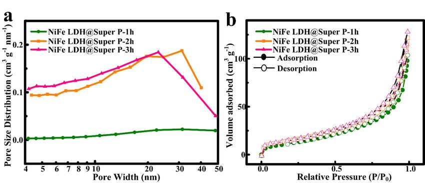
E3S Web of Conferences 257, 01029 (2021)                                                      https://doi.org/10.1051/e3sconf/202125701029
AESEE 2021

      2 Experimental                                                     3 Results and Discuss
                                                                         The XRD patterns of the materials are illustrated in Figure
      2.1 Synthesis of the NiFe LDH@Super P                              1. The diffraction peaks of the samples are indexed to NiFe
                                                                         LDH, agreeing well with the standard powder diffraction
      All chemicals are analytically pure and can be used
                                                                         patterns (JCPDF no. 40-0215)[8]. Specifically, the
      directly after purchase without further purification. NiFe
                                                                         characteristic peaks of the (003), (006), (012), (110) and
      LDH@Super P with Ni:Fe ratio of 2:1 was synthesized
                                                                         (113) crystal planes of NiFe LDH are located at 11.6°,
      using a steped hydrothermal method. In a typical
                                                                         23.45°, 34.4°, 59.9° and 61.3° respectively, and the peak
      procedure, 3.6 mmol of Ni(NO3)2ꞏ6H2O, 1.8 mmol of
                                                                         shape is sharp, indicating that the crystallinity of the
      Fe(NO3)3ꞏ9H2O, 126 mmol of urea and 27 mmol NH4F
                                                                         synthesized sample is high. It is worth noting that the
      were dissolved in 100 ml deionized water at room
                                                                         typical pattern of Super P cannot be found in the XRD
      temperature and stirred to form a homogeneous solution.
                                                                         pattern of the NiFe LDH@Super P composite. This may
      Then it was transferred to a 100 ml Teflon-lined stainless
                                                                         be because the proportion of Super P in the nanocomposite
      steel autoclave and kept at 100 °C for a certain period of
                                                                         is so low that the peak of NiFe LDH is completely covered
      time. Then 0.05 mg Super P was added to it for the second
                                                                         the peak of Super P. In addition, the peak intensity of NiFe
      hydrothermal treatment. After cooling down to room
                                                                         LDH@Super P-1 is relatively low, possibly because the
      temperature, the resulting powder was collected by
                                                                         direct addition of Super P to the mixed solution affects the
      centrifugation, washed 5 times with deionized water and
                                                                         normal nucleation process of NiFe LDH.
      dried at 60 °C for 12 h in a vacuum drying oven.
          For comparison, the second hydrothermal treatment
      time were 1 h, 2 h, and 3 h, respectively. The
      corresponding powders were labelled as NiFe
      LDH@Super P-1h, NiFe LDH@Super P-2h, NiFe
      LDH@Super P-3h. In addition, in order to serve as a
      comparative sample, NiFe LDH@Super P is also directly
      synthesized by one-step hydrothermal method, that is,
      0.05 mg Super P is added to the mixed solution before the
      hydrothermal treatment, and it is named NiFe
      LDH@Super P-1.

      2.2 Characterization
      The X-ray diffraction (XRD) of the sample was
      characterized by an X-ray diffractometer (DX-2700) at
      35 kV and 25 mA using CuKα radiation (λ = 1.5418 Å).                          Figure 1. XRD patterns of the samples.
      A specific surface area and pore size analyzer (JW-                    The morphological characteristics of NiFe
      BK222, China) was used to perform the N2 adsorption-               LDH@Super P synthesized under different conditions
      desorption isotherm. Use field emission scanning                   were revealed by field emission scanning electron
      electron microscope (JSM-6700F) to characterize the                microscope (FESEM). Figure 2a shows the structure of the
      micro morphology of the sample.                                    NiFe LDH@Super P-1. There is fewer NiFe LDH
                                                                         nanoflower formed, and most of the observations are
      2.3 Oxygen evolution reaction (OER) tests and                      agglomerated carbon particles, which shows that mixing
          electrochemical measurements                                   Super P and salt solution directly will have a serious
                                                                         impact on the growth of NiFe LDH. This is also consistent
      The electrochemical measurement was performed on a                 with the XRD analysis results. From Figure 2b, the flower-
      CHI604E electrochemical workstation with a standard                like NiFe LDH is formed, but the distribution of NiFe
      three-electrode system. 1 M KOH solution was used as the           LDH nanoflowers is relatively scattered and small in size,
      electrolyte. The counter electrode is a Pt wire net, and the       which indicates that the precursors in the first stage have
      reference electrode is a Hg / HgO electrode. A glass               not been fully developed. When the pre-hydrothermal
      carbon electrode (GCE) with a diameter of 3 mm was used            time is 2 h (Figure 2c-d), a large number of uniform
      as the working electrode. All test patterns are corrected by       flower-like microspheres appeared and the thickness of
      ohmic compensation. Cyclic voltammetry curves (CVs)                the nanosheet is about 20 nm, which proves that the
      were performed between 1.0 and 1.7 V vs. RHE at a scan             synthesized NiFe LDH is a nanostructure. At the same
      rate of 100 mVꞏs-1. Linear sweep voltammetry (LSV)                 time, the NiFe LDH nanoflower is evenly in-situ loaded
      measurements were recorded from 0.2-0.8 V vs. Hg/HgO               on Super P. As can be seen from Figure 2e-f, when the pre-
      with a scan rate of 10 mVꞏs-1 for the polarization curves.         hydrothermal time is 3 h, the morphology of NiFe
      The Tafel slopes were obtained by plotting the                     LDH@Super P-3h is almost the same as that of NiFe
      overpotential (η) against log (j) from LSV curves.                 LDH@Super P-2h. When the pre-hydrothermal treatment
      Electrochemical impedance spectroscopy (EIS) was                   time reaches 2 hours, the precursor of NiFe LDH will
      performed with an overpotential of 0.3 V in the frequency          continue to grow and be perfect during the second
      range of 0.01 to 105 Hz.

                                                                     2
E3S Web of Conferences 257, 01029 (2021) https://doi.org/10.1051/e3sconf/202125701029
AESEE 2021
hydrothermal treatment, and it can be loaded on Super P
very well.
Figure 2. SEM images of (a) NiFe LDH@Super P-1, (b) NiFe LDH@Super P-1h, (c-d) NiFe LDH@Super P-2h and (e-f) NiFe
LDH@Super P-3h.
Figure 3. (a) Pore size distribution and (b) N2 adsorption-desorption isotherm curves of the samples.
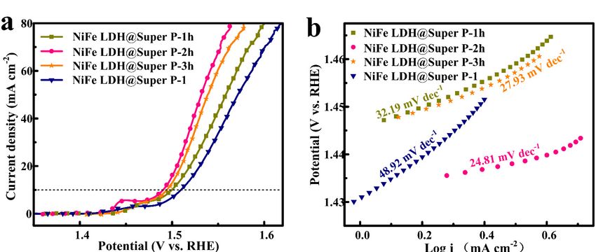
The pore structure and specific surface area of all The as-prepared electrocatalysts were systematically
samples synthesized under different hydrothermal evaluated for oxygen evolution reaction (OER). Figure 4a
conditions were determined by low-temperature nitrogen presents the linear sweep voltammograms (LSV) curves
adsorption/desorption measurements. It can be seen from of all samples, which clearly shows that the NiFe
Figure 3 that all isotherms are shown as typical type IV LDH@Super P-2h sample exhibits the smallest
with H3 hysteresis loop, which is in good agreement with overpotential of 260 mV at the current density of 10
previous reports[9]. The size distribution (Figure 3a) mAꞏcm-2 and the earliest onset of potential compared with
exhibits an average pore size of 15-30 nm. Moreover, the the other samples. Obviously, the polarization curve of the
specific surface areas of NiFe LDH@Super P-1h, NiFe NiFe LDH@Super P-1 sample is the worst, and its η10 is
LDH@Super P-2h and NiFe LDH@Super P-3h are 49.88, 20 mV higher than that of NiFe LDH@Super P-2h. Tafel
60.283 and 61.989 m2ꞏg-1, respectively. The smaller slope is also a useful parameter to describe the kinetics of
specific surface area of NiFe LDH@Super P-1h may be water electrolysis. The Tafel diagram (Figure 4b) obtained
due to the fact that NiFe LDH nanoflower has not been from the polarization curve of each NiFe LDH@Super P
formed in large quantities. However, these relatively large also shows that the NiFe LDH@Super P-2h sample has
specific surface areas and mesoporous channels will the lowest Tafel slope of 24.81 mVꞏdec-1, which further
expose more active sites, which will further lead to faster indicates its highest intrinsic catalytic activity among
penetration of electrolyte and rapid diffusion of molecular them[11]. The predictable maximum tafel slope of NiFe
oxygen during the OER process[10]. LDH@Super P-1 sample is 48.92 mVꞏdec-1. It can be seen
3E3S Web of Conferences 257, 01029 (2021) https://doi.org/10.1051/e3sconf/202125701029
AESEE 2021
from Figure 4c that the resistance of the catalysts can be the current density loss is negligible (Figure 4d), which
greatly reduced after the pre-hydrothermal treatment, confirms the working stability of the electrode. In addition,
which also shows that Super P as a carrier can greatly the cycle stability of other catalysts was also tested. The
enhance the conductivity. In practical applications, the cycle stability performance of NiFe LDH@Super P-1 is
long-term durability of catalytic electrodes is another key relatively poor. As the cycle time increases, its
issue to be considered, especially for these nanostructured overpotential also gradually increases, especially at higher
films, whether they have good durability determines current density, which may be due to the weak bond
whether they have practical value. We examined the between NiFe LDH and Super P. This shows that the
stability of the most catalytically active NiFe synthesis process of pre-hydrothermal treatment and then
LDH@Super P-2h sample for OER. After a long-term adding Super P as a support has a significant effect on the
cycle of 3000 cycles at a scan rate of 100 mVꞏs-1, its improvement of OER catalytic performance.
polarization curve is almost the same as the initial one, and
Figure 4. Electrocatalytic OER performances of the samples. (a) LSV polarization curves, (b) Tafel plots, (c) Electrochemical
impedance spectras and (d) LSV curves of NiFe LDH@Super P-2h before and after cycling tests.
excellent compounding effect with Super P, which could
4 Conclusion expose more active sites and provide a more convenient
way of charge/mass transfer, thus speeding up the OER
In summary, the NiFe LDH@Super P catalysts were electrochemical reaction kinetics. This study affords a
fabricated by pre-hydrothermal treatment method. The as facile and cost effectively strategy to realize the best
synthesized NiFe LDH@Super P-2h sample exhibited performance of OER catalysts, which will provide an
excellent OER performances in alkaline media, with an effective way to rationally design other transition metal
overpotential of only 260 mV at the current density of 10 LDHs electrocatalysts suitable for a wide range of
mA · cm-2. Moreover, after long-term CV cycle technical applications.
measurement, the performance loss of the material is
almost negligible, and it can still maintain very high
electrocatalytic activity. The excellent OER
electrocatalytic performance is mainly attributed to its
unique three-dimensional nanoflower structure and
4E3S Web of Conferences 257, 01029 (2021) https://doi.org/10.1051/e3sconf/202125701029
AESEE 2021
References
1. Seh, Z. W.; Kibsgaard, J.; Dickens, C. F.;
Chorkendorff, I.; Norskov, J. K.; Jaramillo, T. F.
Science. 355, eaad4998 (2017)
2. Wang, JH.; Cui, W.; Liu, Q.; Xing, ZC.; Asiri, AM.;
Sun, XP. Adv. Mater. 28, 215-230 (2016)
3. Suen, N. T.; Hung, S. F.; Quan, Q.; Zhang, N.; Xu, Y.
J.; Chen, H. M. Electrocatalysis for the oxygen
evolution reaction: recent development and future
perspectives. Chem. Soc. Rev. 46, 337–365 (2017)
4. Kuai, CG.; Zhang, Y.; Wu, DY.; Sokaras, D.; Mu,
LQ.; Spence, S.; Nordlund, D.; Lin, F.; Du, XW. ACS
Catal. 9, 6027–6032 (2019)
5. Lu, ZY.; Xu, WW.; Zhu, W.; Yang, Q.; Lei, XD.; Liu,
JF.; Li, YP.; Sun, XM.; Duan, X. ChemComm. 50,
6479–6482 (2019)
6. Gao, ZW.; Liu, JY.; Chen, XM.; Zheng, XL.; Mao, J.;
Liu, H.; Ma, T.; Li, L.; Wang, WC.; Du, XW. Adv.
Mater. 2019, 31, 1804769 (2019)
7. Ni, YM.; Yao, LH.; Wang, Y.; Liu, B.; Cao, MH.; Hu,
CW. Nanoscale. 9, 11596–11604 (2017)
8. .Shen, J.; Zhang, P.; Xie, RS.; Chen, L.; Li, MT.; Li,
JP.; Ji, BQ.; Hu, ZY.; Li, JJ.; Song, LX.; Wu, YP.;
Zhao, XL. ACS Appl. Mater. Interfaces. 11, 13545–
13556 (2019)
9. Li, X.; Fan, ML.; Wei, DN.; Wang, XL.; Wang, YL.
J. Electrochem. Soc. 167, 024501 (2020)
10. Zhan, TR.; Zhang, YM.; Liu, XL.; Lu, SS.; Hou, WG.
J. Power Sources. 333, 53–60 (2016)
11. Peng, CL.; Ran, N.; Wan, G.; Zhao, WP.; Kuang, ZY.;
Lu, Z.; Sun, CJ.; Liu, JJ.; Wang, LZ.; Chen, HR.
ChemSusChem. 13, 811–818 (2020)
5You can also read