NON-CONTROLLED CLOSE-RANGE PHOTOGRAMMETRY METHOD BASED ON PHOTOMODELER SCANNER
←
→
Page content transcription
If your browser does not render page correctly, please read the page content below
The International Archives of the Photogrammetry, Remote Sensing and Spatial Information Sciences, Volume XLII-3/W10, 2020
         International Conference on Geomatics in the Big Data Era (ICGBD), 15–17 November 2019, Guilin, Guangxi, China

   NON-CONTROLLED CLOSE-RANGE PHOTOGRAMMETRY METHOD BASED ON
                     PHOTOMODELER SCANNER

                             HUANG Chang-cheng1, LI Yun-jian2, TANG Shi-hua1, ZHANG yan1, XIAO yan1

             College of Geomatics and Geoinformation Guilin University of Technology, Guilin, China - gut@glut.edu.cn
             1

    2
        Guangxi Zhuang Autonomous Region Surveying and Mapping Geographic Information Product Quality Inspection Station,
                                                       Nanning, China

KEY WORDS: Close-range Photogrammetry; PhotoModeler Scanner; USB Camera; Non-controlled; Detail Survey

ABSTRACT:

Aiming at the high demand of close-range photogrammetry for the object control points and the inconvenient carrying of digital
camera to take photogrammetry in the field, a method of detail survey based on PhotoModeler Scanner software is proposed. USB
camera combines with the centering rod, USB camera captures image data, Total station obtains the coordinates of the centering rod,
the coordinate of projective center is calculated by using the coordinate of the centering rod, PhotoModeler Scanner software
processes image data and coordinate data. Ultimately, image stereo measurement of the no object control point was realized. The
experimental results showed that the error of the plane position of the solved target point was less than 10cm at a shooting distance
of about 10m, and it met the accuracy requirements of detail survey. Therefore, the method can reduce the workload of field detail
survey, reduce the cost and volume of the photographic equipment, and has certain application value.

1 INTRODUCTION                                                        station system that combined ordinary digital camera and total
                                                                      station to realize close-range photogrammetry without control
    Close-range photogrammetry has the characteristics of             points. The photographic total station system can quickly and
instantaneous acquisition of rich information of the measured         efficiently obtain the point cloud model of buildings [7]. Gao
object, non-contact measurement, non-injury to the measured           shen et al. had designed a detail survey method of GPS RTK
object, easy storage of information, reusable information, high       and ordinary camera independent absolute orientation. The
measurement accuracy, low cost, fast speed, low labor intensity       method realized the close-range photogrammetry without
in field, etc. and Close-range photogrammetry is widely used in       ground control points, and the accuracy of detail survey points
various    fields   [1-2].   The   application   of   close-range     was better than 10cm[8].Wang xinyu et al. directly combined
photogrammetry in detail survey can complement the                    the theodolite and camera to realize automatic measurement of
disadvantages of traditional measurement methods of detail            visual guidance theodolite, and conducted observation through
survey and improve the efficiency [3-4].Zhang zuxun et al.            image sensor instead of human eyes aiming at the target. The
proposed a photo total station system(PTSS), which was an             combiner he designed had a high degree of automation, but the
integration of mature digital photogrammetry technology and           production is difficult and their cost is high [9].
high-precision engineering measuring instrument (total station)            Fixed connection of non-measuring digital camera with
[5].Yang liu designed a photographic theodolite system by             theodolite, total station, GPS RTK or other devices would
fastening a non-measuring digital camera with a theodolite            make measuring equipment cumbersome and be not conducive
telescope, which can reach the accuracy level of medium-level         to field measurement [10]. Traditional photogrammetry can
close-range photogrammetry (point position error was less than        achieve high precision measurement, but it needs to arrange the
5 mm) [6].He yingpeng had designed a photographic total               object control point. Traditional photogrammetry is not suitable

First author: HUANG Chang-cheng - E-mail: 312263588@qq.com.
Corresponding author: LI Yun-jian - E-mail: 53521295@qq.com

                                                  This contribution has been peer-reviewed.
                    https://doi.org/10.5194/isprs-archives-XLII-3-W10-1253-2020 | © Authors 2020. CC BY 4.0 License.             1253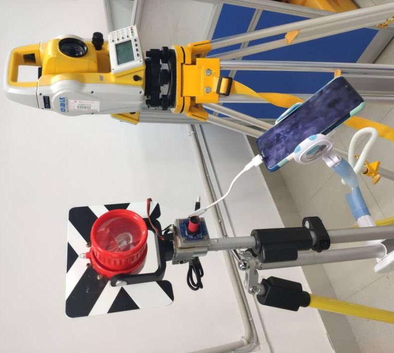
The International Archives of the Photogrammetry, Remote Sensing and Spatial Information Sciences, Volume XLII-3/W10, 2020
International Conference on Geomatics in the Big Data Era (ICGBD), 15–17 November 2019, Guilin, Guangxi, China
for the measurement which requires simple and quick operation Secondly, the vertical height from the bottom of the
and lower precision. In this paper, USB camera is adopted to centering rod to the projective center is h, the plane distance
shoot images. Although the imaging effect is not as good as from the centering rod to the projective center is d, and the
that of digital camera, the weight and volume of the device are azimuth of the centering rod to the projective center is . The
reduced, making field measurement more convenient. By using three-dimensional coordinates of the projective center point are
the characteristics of PhotoModeler Scanner, a measurement as follows: ( x+dsin , y +dcos ,z +h) .
method is designed, which gets rid of the dependence on object Finally, we can complete the absolute orientation of the
control points in photogrammetry. The method can meet the image and the image stereo measurement by using the
precision requirements of 1:500 digital mapping within a calculated coordinates of the three projective center points.
certain distance.
2 COMPOSITION AND DESIGN IDEAS OF
EQUIPMENT
The purpose of the design is to use the three-dimensional
coordinates of three known shooting sites as the basic data in
the case of no object control point coordinates, and to build a
digital model in PhotoModeler Scanner software to realize the
three-dimensional coordinate measurement of the target points
to be measured. For this purpose, a set of close-range
photogrammetry equipment is designed, including a centering Figure 1. Schematic diagram of equipment structure
rod, a prism, a USB camera, an angle sensor, a smartphone, an
OTG data cable. A total station observes the prism mounted on
the centering rod, and the prism and centering rod are to obtain 3 THE BASIC THEORY OF CLOSE-RANGE
the coordinates of the shooting sites, and then the coordinates PHOTOGRAMMETRY
of the shooting sites will be converted into the coordinates of
the projective center in computer. The USB camera is fixed on 3.1 Calibration of Cameras
the centering rod, and the projective center light of the camera
is perpendicular to the centering rod. The angle sensor is Before using the ordinary digital camera to carry on the
mounted on the camera to measure the azimuth angle of the close-range photogrammetry, it must carry on the strict
main optical axis of the camera. The smartphone is mainly calibrating, in order to restore the relative geometry relation
used for manipulate USB cameras and angle sensors and stores between the projective center and the image [11]. USB camera
data. The OTG data cable is used for data transmission must be calibrated before taking images. The main content of
between smartphone and USB camera and angle sensor. The the camera calibration is to obtain the basic information of the
close-range photogrammetry equipment is shown in figure 1. camera, lens distortion parameters and the inside azimuth
General design idea: element of the camera. In this paper, a camera calibration
First, the centering rod is placed on an appropriate point, method based on 2D targets proposed by Mr. Zhang zhengyou
which is called the shooting site. The USB camera aims at is adopted. This method only needs the relationship between
some target points to shoot an image, and the corresponding points in multiple images to achieve camera
three-dimensional coordinates (x, y, z) of the shooting sites are calibration, which is simple and flexible, and its accuracy can
measured by the total station. In this way, image data and meet the requirements of this experiment [12-13].
location data are collected at three locations that are not The calibration steps of USB camera are as follows. Frist,
collinear. The main optical axis of photography keep 45° from the indoor
This contribution has been peer-reviewed.
https://doi.org/10.5194/isprs-archives-XLII-3-W10-1253-2020 | © Authors 2020. CC BY 4.0 License. 1254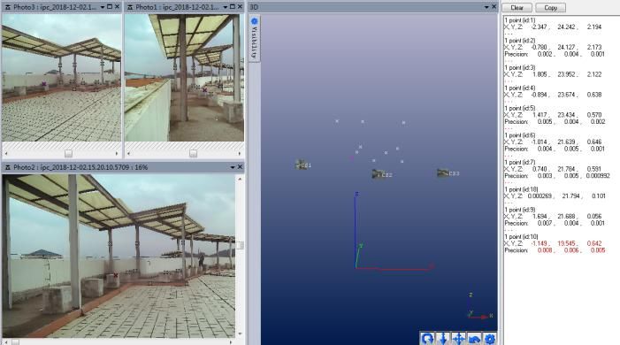
The International Archives of the Photogrammetry, Remote Sensing and Spatial Information Sciences, Volume XLII-3/W10, 2020
         International Conference on Geomatics in the Big Data Era (ICGBD), 15–17 November 2019, Guilin, Guangxi, China

horizontal calibration board. Second, USB camera shoots 4                   zero, in other words, the formula is              ·       ×        = 0 . The
banner images from 4 directions, and then rotates 90° with the              relative orientation of the continuous image pair is based on the
main optical axis of the lens to shoot 4 longitudinal images.               left image, and the relative orientation elements of the right
Finally, eight images are imported into PhotoModeler Scanner                image relative to the left image are obtained. Now, the
software for camera calibration [14]. The images and part of                image-space coordinate system of the left image is taken as the
the processing process are shown in figure 2.                               image-space auxiliary coordinate system. Then, the relative
                                                                            orientation elements of the left and right images are:
                                                                                 Left image:        = 0,       = 0,       = 0,        = 0,      = 0,
                                                                               =0
                                                                                 Right mages:         =    ,     =        ,       =    , , ,
                                                                                 Since          only affects the size of the model established
                                                                            after relative orientation, and does not affect the establishment
                                                                            of the model, there are only five elements to be solved with
                                                                            respect to relative orientation:          ,       ,   ,    ,     . These five
           Figure 2. Processing of camera calibration                       elements are called continuous images of relatively oriented
                                                                            elements. Q value is the upper and lower parallax of model
     The quality of camera calibration can be evaluated by                  points in relative orientation. In stereo image pairs, an equation
image point residuals. It can be seen from the effect diagram of            Q can be listed for each pair of eponymous image point
image point residuals magnified by 1000 times to the left of                coordinates measured and inner azimuth elements are known.
figure 2 that the image point residuals are small and have no               The upper and lower parallax Q=0 marks the completion of
fixed direction, indicating that the camera calibration method is           relative orientation, and there are 5 unknown relative
stable, reliable and high precision. The report of calibration              orientation elements. Therefore, at least 5 pairs of eponymous
showed that the focal length of USB camera was 4.893054mm,                  image points should be measured and 5 equations of Q listed.
and the image format size was 3264×2448 pixels, and the                     When there are redundant observed values, that is, the number
coordinates of the main image point were (3.3029, 2.2827) mm.               of equations is more than the number of unknowns, the error
At the same time, the data of lens distortion and accuracy                  equation should be listed and calculated according to the
evaluation were showed, which showed that the accuracy of the               adjustment of least square principle. In photogrammetry, the
calibration results met the requirements.                                   relative orientation process does not need the coordinates of
                                                                            control points, but only needs the image coordinates of 6 pairs
3.2 Relative Orientation and Absolute Orientation of                        of obvious image eponymous points in the overlapping range
Images                                                                      to solve the relative orientation elements. Images are imported
                                                                            into PhotoModeler Scanner, 6 pairs of eponymous points are
     PhotoModeler Scanner software adopts the analytical                    selected to complete the relative orientation of stereo image
method    of    relative   orientation.     The       same    object   is   pairs, and a three-dimensional model including the projective
photographed at two shooting sites and the two images make                  center point is established. This model is only similar to the
up a stereo image pair. All the eponymous rays intersect at an              original object, but its size, orientation and absolute position
object point, which is the internal geometric relationship of the           are not restored.
stereo image pair. The eponymous rays intersect in pairs, that is,               Absolute orientation refers to the process of transforming
each pair of eponymous rays is coplanar with the photographic               the photogrammetric coordinate system of three-dimensional
baseline. Let       and        be the projective center of the left         model into the target coordinate system. The absolute
image and right image,          and         are a pair of namesake          orientation of image requires solving seven absolute orientating
points. The coplanar condition of relative orientation is that the          elements. The seven absolute orientating elements are Φ , Ω ,
mixed product of photographic baseline            =(         ) and a pair   Κ,      X,   Y,       Z, λ . The absolute orientation is called
of eponymous rays          =          and         =          is equal to    "similarity transformation of three-dimensional space with

                                                 This contribution has been peer-reviewed.
                   https://doi.org/10.5194/isprs-archives-XLII-3-W10-1253-2020 | © Authors 2020. CC BY 4.0 License.                                 1255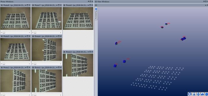
The International Archives of the Photogrammetry, Remote Sensing and Spatial Information Sciences, Volume XLII-3/W10, 2020
International Conference on Geomatics in the Big Data Era (ICGBD), 15–17 November 2019, Guilin, Guangxi, China
different origin" in mathematics. The transformation formula is
as follows:
Xm a1 a2 a3 X P X
Y
m a1 a2 a3 Y P Y
Z a a a3 Z P Z
m 1 2 (1)
In formula (1), ( , , ) is the coordinate of object
point in the target coordinate system. λ is the model scaling
factor. , , (i=1,2,3)are directional cosines of Φ, Ω,
Κ. ( , , ) is the coordinate of object point in the
photogrammetric coordinate system. X, Y, Z are the
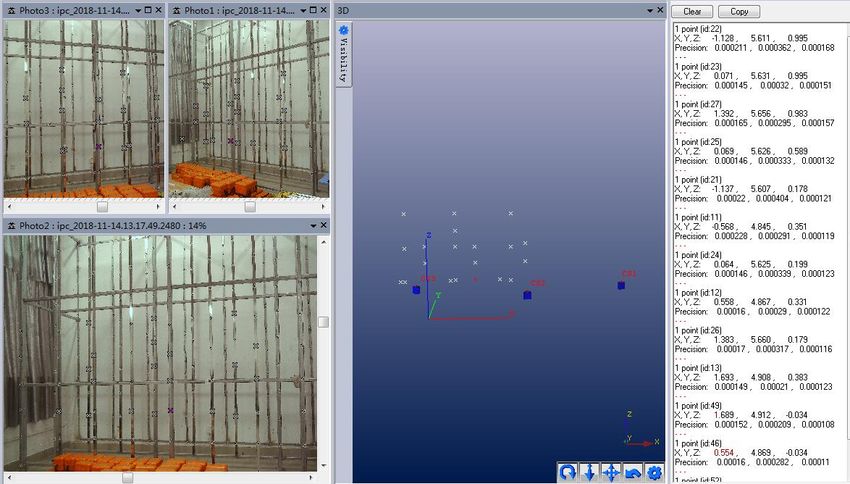
quantity of translation of the coordinate origin. Figure 3. Simple hardware system for close - range
Formula (1) is a nonlinear function, which is linearized photogrammetry
according to the first term of Taylor series formula, and then
solved by iterative method. The formula has seven unknowns, After assembling the hardware system of close-range
and we need at least seven equations to solve these seven photogrammetry, the plane distance from the center of
unknowns. In close-range photogrammetry, if the ground centering rod to the projective center was fixed. This distance
three-dimensional coordinates of three projective center points was measured several times with the total station and averaged,
are known, nine equations can be listed, so there are redundant and the average of this distance was denoted by d, and the
observation values, which can be solved by least square value of d was 0.058m. The vertical height from the bottom of
adjustment. The three-dimensional coordinates of the three the centering rod to the projective center was denoted by h, and
projective center points were inputted in the software the value of h could be calculated by observing the scale of the
PhotoModeler Scanner, to solve the absolute orientation centering rod. The angle sensor was used to measure the
elements, and complete the absolute orientation. azimuth of photographic center light, and this azimuth was
Photogrammetric coordinates of all model points can be denoted by θ. Values of θ can be displayed and recorded by the
transformed into ground measurement coordinates. phone when it was connected to the angle sensor. When the
phone was connected to the USB camera, images from the
USB camera were displayed on the phone, and the phone
4 EXPERIMENTAL ANALYSIS stored images from the USB camera. The three-dimensional
coordinates (x, y, z) of the shooting sites are measured by the
A simple hardware system of close-range photogrammetry total station. The three-dimensional coordinates of the
consists of a USB camera, a centering rod, a prism, an angle projective center point were ( x+ dsin , y + dcos ,z + h) after
sensor, a smartphone and an OTG data line. In addition, a total deductive calculation. The collected three images would be
station is used for measure the coordinates of the shooting sites. imported into PhotoModeler Scanner, 6 pairs of eponymous
The USB camera model is RER-USB8MP02G and it has 8 points would be selected manually in the three images, and
million pixels. The angle sensor model is JY901 and relative orientation of the three images would be conducted to
measurement error of the angle sensor is 1 degree. The simple establish a three-dimensional stereo model. The coordinates of
hardware system of close-range photogrammetry is shown in the three photography center points were inputted into
figure 3. PhotoModeler Scanner to complete the absolute orientation of
the three images. In the end, any target point to be measured
was selected for stereo measurement.
This contribution has been peer-reviewed.
https://doi.org/10.5194/isprs-archives-XLII-3-W10-1253-2020 | © Authors 2020. CC BY 4.0 License. 1256The International Archives of the Photogrammetry, Remote Sensing and Spatial Information Sciences, Volume XLII-3/W10, 2020
International Conference on Geomatics in the Big Data Era (ICGBD), 15–17 November 2019, Guilin, Guangxi, China
The first experimental site was an indoor
three-dimensional control field, in which posts with different
spatial distances were placed, and targets were pasted on the
posts at a certain distance. The second experimental site was
the roof of a teaching building, and some reflectors were
attached to the surfaces of stone benches or pillars. In the two
sites, the pictures of the target point would be shot at three
locations that were not collinear, and the coordinates of the
shooting site would be measured with the total station. The
coordinates of the shooting location were used as the basic Figure 4. Experiment in Indoor Control Field
coordinate data. The total station measured the coordinates of
In figure 4, the left part showed three images, the middle
the target points, and the results were used as check data.
part showed the stereo model of selected target points and
In first experiment, 20 target points on the posts were
camera positions, and the right part showed measurement
selected as the observation target points, which were divided
results. The results of stereo measurement were exported and
into three layers. The distance between the points was 1 to 2
compared with the three-dimensional coordinates of the
meters, and the distances between the shooting sites and the
corresponding points measured by the total station. The
target points were 5 to 8 meters. The experiment process in the
difference between photogrammetric coordinates and total
indoor control field was shown in figure 4.
station coordinates was calculated. The coordinate errors are
shown in table 1.
Table 1. Accuracy Analysis of Indoor Ground Point Coordinates
Target Total Station Coordinates Photogrammetric Coordinates Error Analysis
Number X Y Z X Y Z dX dY dZ
1 -1.138 4.838 -0.454 -1.114 4.850 -0.454 -0.023 -0.012 0.000
2 -0.005 4.868 -0.441 0.019 4.879 -0.443 -0.025 -0.012 0.002
3 1.112 4.900 -0.440 1.138 4.911 -0.444 -0.026 -0.011 0.004
4 -0.568 4.845 0.351 -0.543 4.859 0.350 -0.025 -0.013 0.000
5 0.558 4.867 0.331 0.584 4.880 0.329 -0.026 -0.013 0.002
6 1.693 4.908 0.383 1.721 4.921 0.379 -0.028 -0.013 0.003
7 -1.137 5.607 0.178 -1.113 5.621 0.177 -0.024 -0.014 0.002
8 -1.128 5.611 0.995 -1.103 5.627 0.994 -0.026 -0.016 0.001
9 0.071 5.631 0.995 0.098 5.646 0.993 -0.027 -0.016 0.002
10 0.064 5.625 0.199 0.089 5.639 0.195 -0.026 -0.014 0.003
11 0.069 5.626 0.589 0.096 5.641 0.586 -0.026 -0.015 0.003
12 1.383 5.660 0.179 1.410 5.673 0.174 -0.027 -0.013 0.005
13 1.392 5.656 0.983 1.421 5.671 0.979 -0.028 -0.015 0.004
14 -0.570 4.848 -0.027 -0.546 4.861 -0.028 -0.025 -0.013 0.001
15 0.554 4.869 -0.034 0.580 4.882 -0.036 -0.026 -0.012 0.002
16 1.689 4.912 -0.034 1.716 4.924 -0.038 -0.027 -0.012 0.004
17 0.551 4.872 -0.428 0.576 4.883 -0.431 -0.025 -0.011 0.003
18 -1.148 5.601 -0.627 -1.125 5.614 -0.629 -0.023 -0.012 0.002
19 0.053 5.622 -0.598 0.077 5.634 -0.602 -0.025 -0.012 0.004
20 1.374 5.664 -0.628 1.400 5.675 -0.634 -0.026 -0.012 0.006
RMSE 0.0270 0.0137 0.0030
This contribution has been peer-reviewed.
https://doi.org/10.5194/isprs-archives-XLII-3-W10-1253-2020 | © Authors 2020. CC BY 4.0 License. 1257The International Archives of the Photogrammetry, Remote Sensing and Spatial Information Sciences, Volume XLII-3/W10, 2020
International Conference on Geomatics in the Big Data Era (ICGBD), 15–17 November 2019, Guilin, Guangxi, China
As could be seen from table 1, the standard deviations of
, and were 0.0270m, 0.0137m and 0.0030m
respectively. Horizontal position error was 0.0301m after
calculation. In 1:500 digital mapping, the horizontal position
error was required to be less than or equal to 10cm. Therefore,
the results of this photogrammetry can meet the requirements
of 1:500 digital mapping.
In second experiment, 10 reflectors were attached to the
surfaces of stone benches or pillars on the roof of a teaching
building. The distances between the shooting sites and the Figure 5. Outdoor Photogrammetry Experiment
reflectors were 8 to 12 meters. The method of photogrammetry
is the same as that adopted in first experiment. The process of In the same way, the data of stereo measurement are
outdoor photogrammetry experiment is shown in figure 5. exported and compared with the three-dimensional coordinates
of the corresponding points measured by the total station. The
accuracy analysis of outdoor target point is shown in table 2.
Target Total Station Coordinates Photogrammetric Coordinates Error Analysis
Number X Y Z X Y Z dX dY dZ
1 -2.347 24.242 2.194 -2.371 24.303 2.152 0.024 -0.061 0.043
2 -0.780 24.127 2.173 -0.797 24.190 2.131 0.017 -0.063 0.042
3 1.805 23.952 2.122 1.800 24.017 2.082 0.005 -0.065 0.040
4 -0.894 23.674 0.638 -0.910 23.729 0.591 0.016 -0.055 0.047
5 1.417 23.434 0.570 1.412 23.491 0.525 0.005 -0.057 0.045
6 -1.014 21.639 0.646 -1.028 21.685 0.607 0.014 -0.046 0.040
7 0.740 21.784 0.591 0.734 21.832 0.552 0.006 -0.048 0.040
8 1.694 21.688 0.056 1.693 21.736 0.015 0.001 -0.047 0.041
9 -1.149 19.545 0.642 -1.160 19.581 0.610 0.012 -0.036 0.032
10 0.000 21.794 0.101 -0.009 21.840 0.059 0.009 -0.046 0.042
RMSE 0.0124 0.0496 0.0390
As could be seen from table 2, the standard deviations of PhotoModeler Scanner could work out the three-dimensional
, and were 0.0124m, 0.0496m and 0.0390m coordinates of the target points and the measurement accuracy
respectively. Horizontal position error was 0.0511m after met the requirements of digital mapping.
calculation. The results of outdoor photogrammetry also can
meet the requirements of 1:500 digital mapping.
By comparing these two experiments, it could be found 5 CONCLUSION
that the error of experiment one was small and that of
experiment two was large. The main reason was the shooting In this paper, the USB camera is combined with the
distance and the shooting environment. The measurement error centering rod. Three pieces of image and three-dimensional
would increase with the measurement distance. The complex coordinates of three shooting sites are taken as the basic
environment would lead to measurement errors, such as calculation data, which are processed in PhotoModeler Scanner
unreasonable light was not conducive to the collection of software. Finally, the three-dimensional coordinates of the
images. This method could easily and quickly collect data target point are calculated and will be applied to detail survey.
outdoors. At the shooting distance of about 10 meters, The experiment showed that when the shooting distance was
This contribution has been peer-reviewed.
https://doi.org/10.5194/isprs-archives-XLII-3-W10-1253-2020 | © Authors 2020. CC BY 4.0 License. 1258The International Archives of the Photogrammetry, Remote Sensing and Spatial Information Sciences, Volume XLII-3/W10, 2020
International Conference on Geomatics in the Big Data Era (ICGBD), 15–17 November 2019, Guilin, Guangxi, China
about 10 meters, the error in the plane position of the target and Mapping, 2017, 42(01): 107-112.
point was less than 10cm, and the accuracy met the [9] WANG Xinyu, FAN Baixing, YU Ying, et al. An automatic
requirements of detail survey. This method effectively solves measurement method with visual guiding theodolite[J].
the limitation of the object control points which close-range Engineering of Surveying and Mapping, 2018, 27(6):32-40.
photogrammetry needed for, and makes full use of the [10] JU Xinghua. Implementation of non-control close-range
advantage that close-range photogrammetry can carry out photogrammetry system and its application[J]. Science of
stereo measurement without contacting the target points. In Surveying and Mapping, 2012, 37(3):188-190.
addition, the equipment can reduce the field workload of detail [11] CHENG Xiaojun, XU Chengquan ,ZHOU Xingquan. A
survey, and reduce the volume, weight and cost of Research on Rapid Calibration of Ordinary Digital Camera
photographic equipment, thus it has certain application value. Based on PhotoModeler Scanner System[J]. Remote Sensing
In order to improve the accuracy of stereo measurement, the Information, 2011(4): 80-84.
system error is minimized when the equipment is installed. [12] Zhang, Zhengyou. A flexible new technique for camera
calibration[J]. IEEE Transactions on Pattern Analysis and
Machine Intelligence, 2000, 22(11):1330-1334.
REFERENCE [13] HE X C, YUNG N H C. New method for overcoming
ill-conditioning in vanishing-point-based camera calibration.[J].
[1] Luhmann T. Close range photogrammetry for industrial OPTICAL ENGINEERING, 2007, 46(3): 037202-037212.
applications[J]. Isprs Journal of Photogrammetry & Remote [14] SONG Yuejun, HUANG Yanhe, YANG Jie, et al.
Sensing, 2010, 65(6): 558-569. Application of close-range photogrammetry technology in soil
[2] Yung-Chuan Chen, Yi-Hsing Tseng. Advancement of close erosion monitoring[J]. Science of Surveying and Mapping,
range photogrammetry with a portable panoramic image 2016, 41(6): 80-83.
mapping system (PPIMS)[J]. PHOTOGRAMMETRIC [15] FANG Ziyan, TANG Jianlin, DONG Xiangyong.
RECORD PHOTOGRAMMETRIC RECORD, 2018, Photogrammetry[M]. Wuhan: Changjiang Publishing House,
Vol.33(162):196-216. 2012: 138-142.
[3] HUANG Yun, DENG Fei, HU Yulei, et al. Application of
Close-range Photogrammetry in the Dry Beach Monitoring[J].
Journal of Geomatics, 2016, 41(3):33-37.
[4] MAO Binbin, ZHANG Qiang, XU Hao, et al. Monitoring
the Displacement and Deformation of the Slope of Hongqigou
Dumping Site by Close-range Photogrammetry[J]. Modern
Mining, 2016, 32(5):151-153.
[5] ZHANG Zuxun, ZHAN Zongqian, ZHENG Shunyi, et al.
Photo Total Station System--The Integration of Digital
Photogrammetry and Total Station[J]. Bulletin of Surveying
and Mapping, 2005(11): 1-5.
[6] YANG Liu. Scheme Argumentation of Camera Transit
Based on Non-Metric Digital Camera[D]. Xi’an: Xi’an
University of Science and Technology, 2006.
[7] HE Yingpeng. Research on precision analysis and error
correction based on Photo Total Station System[D]. Chongqing:
Chongqing Jiaotong University, 2016.
[8] GAO Shen, HU Qingwu, AI Mingyao, et al. Study of detail
mapping method based on independent absolute orientation
with GPS RTK and ordinary camera[J]. Science of Surveying
This contribution has been peer-reviewed.
https://doi.org/10.5194/isprs-archives-XLII-3-W10-1253-2020 | © Authors 2020. CC BY 4.0 License. 1259You can also read