NORTHSTAR 154 BATH/SPA TV - Installation Instructions
←
→
Page content transcription
If your browser does not render page correctly, please read the page content below
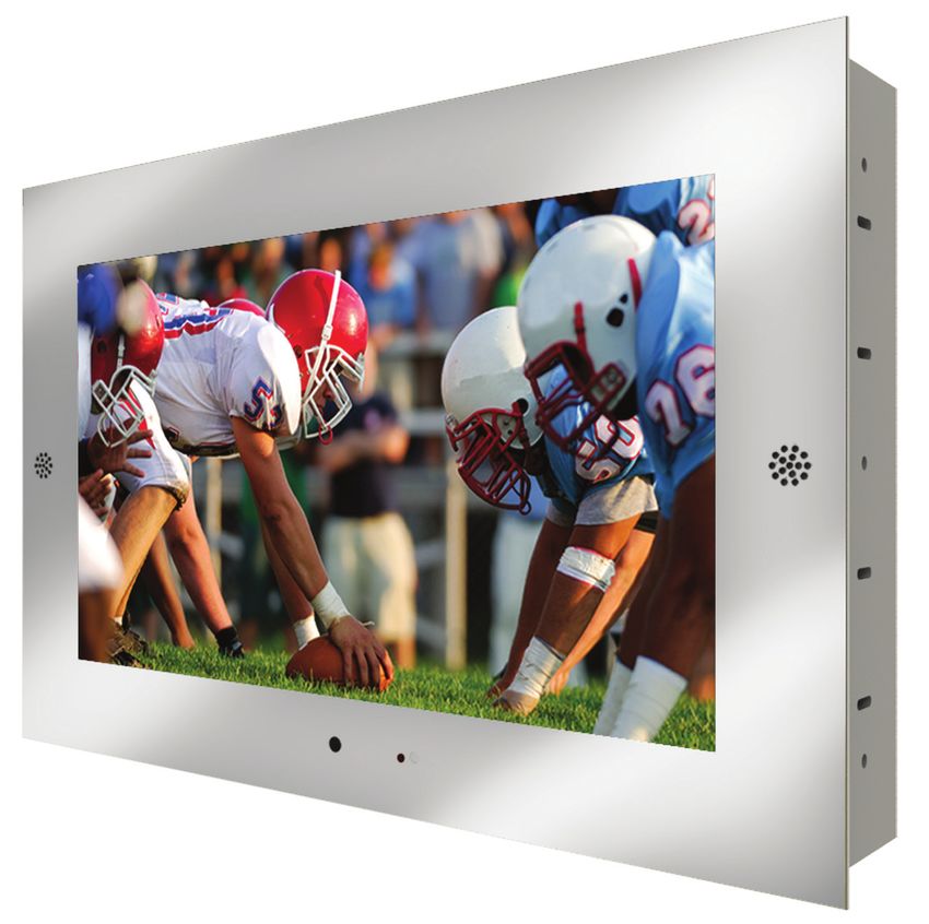
NORTHSTAR™
154 BATH/SPA TV
Installation Instructions
IMPORTANT SAFETY INSTRUCTIONS
    Must be installed by a qualified electrician
    Read these instructions. Keep these instructions for future use.
    Install in accordance with manufacturer’s instructions.

    This product is suitable for wet locations. Clean only with water, mild soap and soft cloth. Do not clean with harsh
    detergents.

    Do not install near any heat sources such as radiators, heat registers, stoves, or other apparatus
    (Including amplifiers) that produce heat.

    Do not defeat the safety purpose of the grounding-type plug.
    A grounding-type plug has two blades and a third grounding prong.
    The third prong is provided for your safety. If the provided plug does not fit into your outlet, consult an electrician
    for replacement of the obsolete outlet.

    Protect the power cord from being walked on or pinched particularly at plugs, convenience receptacles, and
    where they exit from the appliance.

    Only use attachments/accessories specified by the manufacturer.

    Unplug this apparatus during lightning storms or when unused for long periods of time.

    Refer all servicing to qualified service personnel. Servicing is required when the apparatus has been damaged in
    any way, such as: power-supply cord or plug is damaged, liquid has been spilled or objects have fallen into
    the apparatus, the apparatus has been exposed to rain or moisture, does not operate normally, or has been
    dropped.

    Terminals that are marked with a lightning flash are hazardous. Any external wiring connections to these terminals
    requires installation by an electrician.

    CAUTION
    READ ALL INSTRUCTIONS PRIOR TO INSTALLATION

    WARNING:
    TO PREVENT INJURY, THE BATH/SPA TV MUST BE INSTALLED IN ACCORDANCE WITH THE MANUFACTURER’S
    INSTRUCTIONS

    CAUTION: NO USER-SERVICEABLE PARTS INSIDE. REFER SERVICING TO QUALIFIED PERSONNEL. BEWARE
    OF STATIC SENSITIVE PARTS.

    UNPACKING YOUR BATH/SPA TV
    Verify Contents
    Prior to installation unpack items and verify contents. The Bath/Spa TV comes with the following components:
    1. In-Wall box with right angled plastic L-channel pieces
    2. A NRTL Approved Power Supply, 15 Watts AC/DC, 90-264 Volts input and 12 Volts output
    3. Power cord
    4. HDMI cable
    5. RF Cable
    6. LCD-TV with glass face and stainless steel bezel
    7. Remote Control

2                     THERE’S ONLY ONE™ ELECTRIC MIRROR® | E sales@electricmirror.com | T +1 425 776-4946 | F +1 425-491-8200 | W www.electricmirror.com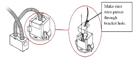
INSTALLATION
Please note that all electrical installations should be carried out by a fully qualified electrician
in conformance with the National Electrical Code.

ßCut a 15-1/2” W X 11-1/2” H X 3-1/2” deep recess in the wall board to accommodate the In-Wall Box. The recess
in the wall should be open below the In-Wall Box to allow cables to enter the bottom of the unit. The wall should
be of suitable strength to support the weight of the Bath/Spa TV (32.5 lbs). Vertically mounted 2” x 4” wall studs
may be used to provide extra support to the wall board.

CABLING AND ELECTRICAL INSTALLATION
Please note, all electrical installation should be carried out by a fully qualified electrician in conformance with the
National Electrical Code.

Electrical Outlets
The LCD-TV requires a GFCI receptacle in which to plug the12-120V AC/DC adapter. Install a receptacle for this
adapter. The receptacle should be located in a readily accessible area in a dry location.
FAILURE TO DO SO MAY RESULT IN DEATH OR SERIOUS INJURY

Plug the power supply cable of the AC/DC adapter into the outlet. The power adapter is not waterproof and
therefore must be positioned in a dry, well-ventilated, accessible area away from water, moisture or heat source.

The 12V side of the AC/DC adapter powers the Northstar LCD-TV. The AC/DC adapter of the LCD-TV is fitted
with a 25’ low voltage cable that should be fed behind the wall to the LCD-TV. Make sure there are two (2) feet of
extra slack at the LCD-TV to allow the power connector to be plugged into the TV for installation. The low voltage
cable should not be cut, shortened or lengthened in any way. Doing so may cause damage to the unit and voids
all warranty.

THERE’S ONLY ONE™ ELECTRIC MIRROR® | E sales@electricmirror.com | T +1 425 776-4946 | F +1 425-491-8200 | W www.electricmirror.com   3
Audio Connection
    The Bath/Spa TV will use a ceiling speaker (see speaker specification for installation). This is an easily installed
    speaker option for small rooms. Place speaker cable behind wall running from the Bath/Spa TV to the ceiling
    speaker.

    Video Connection
    The Northstar LCD-TV has the following video input options:
    RF Connection
    Composite Connections
    S-Video Connection
    VGA Connection
    HDMI Connection

    INSTALLING THE MOUNTING BRACKET
    Level and attach the In-Wall Box into the wall using the twelve (12) screws provided.

    INSTALLING THE LCD-TV
    Remove the Northstar 154 LCD-TV from its packaging. The back of the TV has a cable outlet module with cables
    configured to the customer’s requirements. In the proper orientation the cables exit downward out of the module.
    Make sure the appropriate cables and their connectors are present. These include a low-voltage power cord and
    audio/video source connectors.

    Fit the Northstar 154 LCD-TV into the In-Wall Box by aligning the unit on the plastic L-Channel pieces. Push the
    TV towards the back of the In-Wall box until the magnetic force is apparent. Be careful with your hand placement
    to avoid having your fingers in between the stainless steel bezel and the wall when the magnetic force takes full
    effect.

4                      THERE’S ONLY ONE™ ELECTRIC MIRROR® | E sales@electricmirror.com | T +1 425 776-4946 | F +1 425-491-8200 | W www.electricmirror.com
Test the LCD-TV Prior to sealing the unit, turn on the LCD TV and make sure it is operating properly. Seal the LCD-TV When you are sure that the unit is installed and operating correctly, turn the TV off and apply a clear non- corrosive* silicone sealant to the joint between the edges of the stainless steel bezel and the wall surface material. Ensure that the silicone is applied into the gap evenly and is applied without any gaps, bubbles, etc. Wipe away any excess silicone. This seal is of the greatest importance to the reliability and safe operation of the unit and must be water tight. The unit will require cleaning and resealing after any service or repair. *Recommended Silicone Sealants Loctite: 51388 Superflex Dow Corning: Any of their neutral-cure flow able silicone adhesives. THERE’S ONLY ONE™ ELECTRIC MIRROR® | E sales@electricmirror.com | T +1 425 776-4946 | F +1 425-491-8200 | W www.electricmirror.com 5
BOSE™ SPEAKER INSTALLATION
If using the ceiling Bose™ FreeSpace®ceiling mount options:
Select Rough-In Pan location on the ceiling. See below for installation steps.
If using the Bose™ wall mount options:
Mark the location of the bracket plate on the wall. See below for installation steps.
The following steps explain how to install the Mirror TV speaker on the ceiling/wall.
There are 3 options when installing a Bose™ speaker on a sheet rock ceiling/ wall, depending on building code
requirements:
a) Direct Wiring
1. Align metal pan on ceiling/wall wood support and screw the pan in place. NOTE: The metal pan is not included
with this package.
2. Place sheet rock underneath the pan and screw it onto the wood.
3. Cut a circular hole out of the sheet rock to match the circular hole in the metal pan.
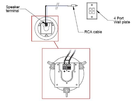
6 THERE’S ONLY ONE™ ELECTRIC MIRROR® | E sales@electricmirror.com | T +1 425 776-4946 | F +1 425-491-8200 | W www.electricmirror.com4. Insert the Bose™ speaker through circular cut out. 5. Connect the RCA cable to the speaker terminal. The live wire (black) is connected to the positive terminal and the neutral wire (white) is wired to the negative terminal. Connect the RCA cable to the speaker source on the 4 port wall plate. 6. Screw the security bracket onto the back of the speaker. THERE’S ONLY ONE™ ELECTRIC MIRROR® | E sales@electricmirror.com | T +1 425 776-4946 | F +1 425-491-8200 | W www.electricmirror.com 7
7. Secure the speaker by tightening all screws. The screws will pull the speaker lock-down and secure the speaker
    in place.

    CONDUIT WITHOUT PLENUM COVER

    1. Install the Bose™ 8/32 junction box onto the metal pan. Connect the conduit with RCA cable inside, to 4-port
    wall plate.

    2. Align the metal pan on a ceiling/wall wood support and screw the pan in place.

8                     THERE’S ONLY ONE™ ELECTRIC MIRROR® | E sales@electricmirror.com | T +1 425 776-4946 | F +1 425-491-8200 | W www.electricmirror.com
3. Place sheet rock underneath the pan and screw it onto the wood. 4. Cut a circular hole out of the sheet rock to match the circular hole in the metal pan. 5. Insert the Bose™ speaker through the circular cut out. THERE’S ONLY ONE™ ELECTRIC MIRROR® | E sales@electricmirror.com | T +1 425 776-4946 | F +1 425-491-8200 | W www.electricmirror.com 9
6. Connect the wire from the junction box cable (covered with conduit) to the speaker terminal. The live wire
     (black) is connected to the positive terminal and the neutral wire (white) is wired to the negative terminal. Screw
     the security bracket onto the back of the speaker.

     7. Secure the speaker by tightening all screws. The screws will pull the speaker locks-down and secure the speaker
     in place.

     CONDUIT WITH PLENUM COVER
     1-5 follow step the same as in: “Conduit without speaker cover” installation.

     Connect the wire from the junction box cable (covered with conduit) to the speaker terminal. The live wire (black)
     is connected to the positive terminal and the neutral wire (white) is wired to the negative terminal. Screw the
     plenum cover onto the top of the speaker.

10                     THERE’S ONLY ONE™ ELECTRIC MIRROR® | E sales@electricmirror.com | T +1 425 776-4946 | F +1 425-491-8200 | W www.electricmirror.com
Secure the speaker by tightening all screws. The screws will pull the speaker lock-down and secure the speaker in place. INSERTING SPEAKER COVER 1. The speaker cover can be installed straight to the speaker if the sheet rock ceiling/wall does not need any additional painting. 2. Use paint protective paper if the exposed speakers area needs to be painted. THERE’S ONLY ONE™ ELECTRIC MIRROR® | E sales@electricmirror.com | T +1 425 776-4946 | F +1 425-491-8200 | W www.electricmirror.com 11
You can also read


