NOVEL SOLUTIONS FOR QUIETER AND GREENER CITIES
←
→
Page content transcription
If your browser does not render page correctly, please read the page content below
Novel solutioNs for quieter aNd greeNer cities
                                                                                                                      Novel solutioNs
                                                                                                                      for quieter aNd
                                                                                                                      greeNer cities

4   Novel solutions for quieter and greener cities                                                    Chapter title                     1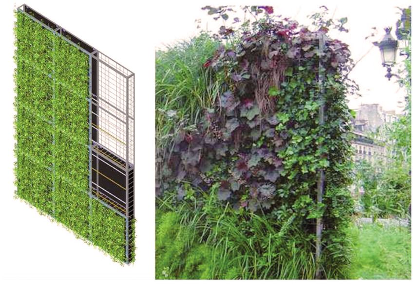
Layout: Martin Zetterquist
Illustrations: Tove Hennix
Print: Alloffset AB, Bandhagen, Sweden
Financed by the European Union Seventh
Framework Programme (FP7/2007-2013)

2                                        Novel solutions for quieter and greener cities   Chapter title
                                                                                                     Chapter title   3   3
Novel solutioNs
for quieter aNd
greeNer cities

                  1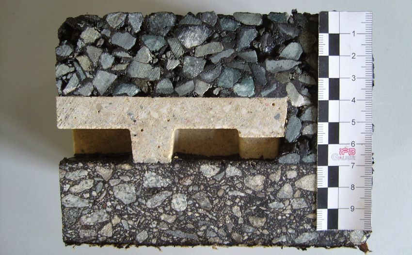
foreword
Vegetated areas and surfaces are greatly appreciated        abatements from our toolbox individually reduce noise
in both urban and rural environments. The beneficial        by 10 dB(A) or more. It should be noted that most of the
effects of greening mean that the costs of new green-       estimated noise reductions have been calculated using
ing or of maintaining existing green surfaces are           advanced numerical methods, rather than measured in
often easy to justify – even without considering            real situations, so a non-negligible uncertainty is expect-
the benefit of environmental noise reduction. The           ed in real situations. To minimize this uncertainty, the
thrust of the project presented in this brochure was        estimation methods have all been validated and are
to find better ways of using vegetated surfaces and         applied in situations that are as realistic as possible. In
recycled materials to reduce road and rail traffic noise    addition, the impairment in performance due to meteo-
and improve the perceived sound environment.                rological effects has been estimated for selected cases
     We present a toolbox containing a large variety of     by modelling the effects of mean wind and turbulence.
measures. Traffic noise situations are often complex and        With this brochure, we would like to encourage
a single noise mitigation measure is seldom sufficient.     the implementation, testing, and further evaluation
Some of the tools we propose each lead to 2–3 dB(A)         of the suggested green noise abatement methods.
in noise reduction, so an appropriate combination of        Detailed information on the project results will be
measures is needed to obtain a larger effect. Other noise   made available in a handbook to be published in 2013.

2                                                                                Novel solutions for quieter and greener cities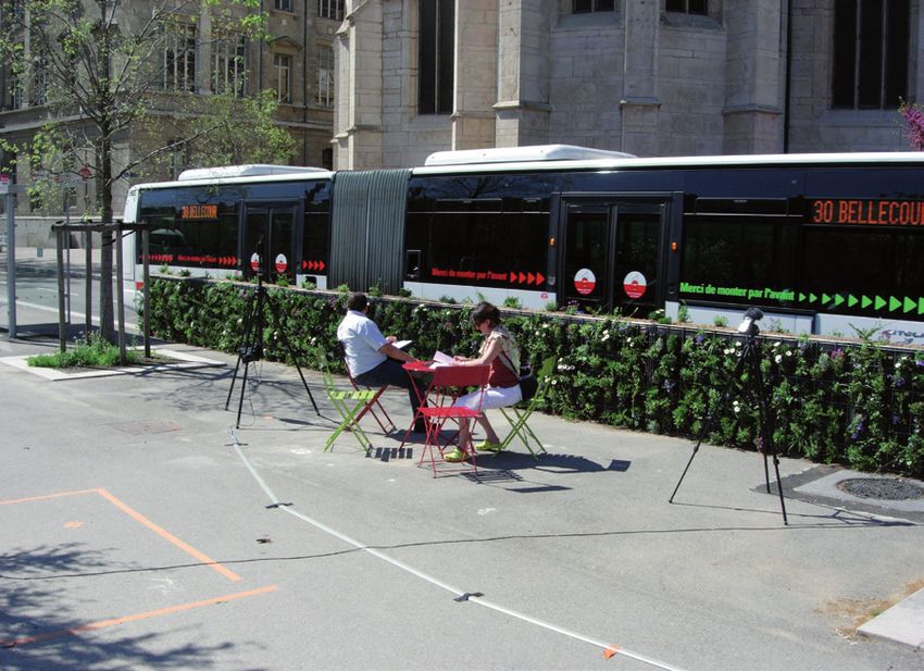
content
The HOSANNA project  .  .  .  .  .  .  .  .  .  .  .  .  .  .  .  .  .  .  .  .  .  .  .  .  .  .  .  .  .  .  .  .  .  .  .  .  .  .  .  .  .  .  .  .  .  .  .  .  .  .  .  .  .  .  .  .  .  .  .  .  .  .  .  .  .  .  .  .  .  .  .  .  .  .  .  .  .  .  .  .5
Introduction  .  .  .  .  .  .  .  .  .  .  .  .  .  .  .  .  .  .  .  .  .  .  .  .  .  .  .  .  .  .  .  .  .  .  .  .  .  .  .  .  .  .  .  .  .  .  .  .  .  .  .  .  .  .  .  .  .  .  .  .  .  .  .  .  .  .  .  .  .  .  .  .  .  .  .  .  .  .  .  .  .  .  .  .  .  .  .  .  .  .6
Principles of noise reduction .  .  .  .  .  .  .  .  .  .  .  .  .  .  .  .  .  .  .  .  .  .  .  .  .  .  .  .  .  .  .  .  .  .  .  .  .  .  .  .  .  .  .  .  .  .  .  .  .  .  .  .  .  .  .  .  .  .  .  .  .  .  .  .  .  .  .  .  .  .  .  .  .  .  .  .  .7
Innovative noise barriers, using natural and recycled materials  .  .  .  .  .  .  .  .  .  .  .  .  .  .  .  .  .  .  .  .  .  .  .  .  .  .  .  .  .  .  .  .  .  .  .  .  .  .  .  .  .  .  .  .  .  .  .  .9
Trees, shrubs, and bushes .  .  .  .  .  .  .  .  .  .  .  .  .  .  .  .  .  .  .  .  .  .  .  .  .  .  .  .  .  .  .  .  .  .  .  .  .  .  .  .  .  .  .  .  .  .  .  .  .  .  .  .  .  .  .  .  .  .  .  .  .  .  .  .  .  .  .  .  .  .  .  .  .  .  .  .  .  .16
Noise reduction by means of ground treatments  .  .  .  .  .  .  .  .  .  .  .  .  .  .  .  .  .  .  .  .  .  .  .  .  .  .  .  .  .  .  .  .  .  .  .  .  .  .  .  .  .  .  .  .  .  .  .  .  .  .  .  .  .  .  .  .  .  .21
Vegetation in urban streets, squares, and courtyards  .  .  .  .  .  .  .  .  .  .  .  .  .  .  .  .  .  .  .  .  .  .  .  .  .  .  .  .  .  .  .  .  .  .  .  .  .  .  .  .  .  .  .  .  .  .  .  .  .  .  .  .  .  . 28
Combining solutions  .  .  .  .  .  .  .  .  .  .  .  .  .  .  .  .  .  .  .  .  .  .  .  .  .  .  .  .  .  .  .  .  .  .  .  .  .  .  .  .  .  .  .  .  .  .  .  .  .  .  .  .  .  .  .  .  .  .  .  .  .  .  .  .  .  .  .  .  .  .  .  .  .  .  .  .  .  .  .  .  . 33
Perceptual effects  .  .  .  .  .  .  .  .  .  .  .  .  .  .  .  .  .  .  .  .  .  .  .  .  .  .  .  .  .  .  .  .  .  .  .  .  .  .  .  .  .  .  .  .  .  .  .  .  .  .  .  .  .  .  .  .  .  .  .  .  .  .  .  .  .  .  .  .  .  .  .  .  .  .  .  .  .  .  .  .  .  .  . 37
Economic analyses  .  .  .  .  .  .  .  .  .  .  .  .  .  .  .  .  .  .  .  .  .  .  .  .  .  .  .  .  .  .  .  .  .  .  .  .  .  .  .  .  .  .  .  .  .  .  .  .  .  .  .  .  .  .  .  .  .  .  .  .  .  .  .  .  .  .  .  .  .  .  .  .  .  .  .  .  .  .  .  .  .  . 43
Summary of noise reduction methods .  .  .  .  .  .  .  .  .  .  .  .  .  .  .  .  .  .  .  .  .  .  .  .  .  .  .  .  .  .  .  .  .  .  .  .  .  .  .  .  .  .  .  .  .  .  .  .  .  .  .  .  .  .  .  .  .  .  .  .  .  .  .  .  .  .  . 46
Glossary  .  .  .  .  .  .  .  .  .  .  .  .  .  .  .  .  .  .  .  .  .  .  .  .  .  .  .  .  .  .  .  .  .  .  .  .  .  .  .  .  .  .  .  .  .  .  .  .  .  .  .  .  .  .  .  .  .  .  .  .  .  .  .  .  .  .  .  .  .  .  .  .  .  .  .  .  .  .  .  .  .  .  .  .  .  .  .  .  .  .  . 48

Content                                                                                                                                                                                                                                                                                   3
Partners
Chalmers University of Technology (Sweden),         TOI (Norway), University of Sheffield (UK),
CSTB (France), Canevaflor (France), IBBT Gent       University of Bradford (UK), Stockholm
University (Belgium), Müller BBM (Germany),         University (Sweden), Acoucité (France), and
Open University (UK), City of Stockholm (Sweden),   Hanyang University (South Korea).

4                                                                       Novel solutions for quieter and greener cities
the HosaNNa project
This brochure summarizes the main findings of the research project “HOlistic and Sustainable
Abatement of Noise by optimized combinations of Natural and Artificial means” (HOSANNA).
The project aimed to develop a toolbox for reducing road and rail traffic noise in outdoor
environments by the optimal use of vegetation, soil, other natural materials and recycled
materials in combination with artificial elements.

The project studied a number of green abatement              The project was coordinated by Chalmers
strategies that might achieve cost-effective improve-    University of Technology (coordinator: Jens
ments using new barrier designs, planting of trees,      Forssén) and involved 13 partners from seven
shrubs, or bushes, ground and road surface treatments,   countries. The research received funding from the
and greening of building facades and roofs. The noise    European Union Seventh Framework Programme
reduction was assessed in terms of sound level reduc-    (FP7/2007–2013) under grant agreement
tions, perceptual effects, and cost–benefit analyses.    n° 234306, collaborative project HOSANNA.

The Hosanna Project                                                                                          5
introduction
Noise from roads and railways is a widespread environmental exposure that adversely affects human
health and well-being and is associated with considerable costs to society. More than half of the
residents of large European cities live in areas where it is likely that noise levels adversely affect their
well-being and health. In addition, many public spaces, such as city parks, esplanades, and green
open spaces, are noise exposed, which reduces these areas’ potential to provide rest and relaxation.

Traffic noise causes annoyance and sleep disturbance, it     GDP, or about one third of the costs of road accidents.
interferes with rest, concentration, and speech commu-           Successful noise reduction will therefore lead
nication and negatively affects children’s learning and      to substantial economic gains and positive effects
school performance. There is also increasingly strong        on public health and well-being. The most effective
support for a causal link between long-term expo-            noise-mitigation method is to reduce noise emissions
sure to road-traffic noise and cardiovascular disease,       at the source, for example, by means of regulations
including hypertension and myocardial infarction.            demanding quieter engines, tires, or road surfaces,
    The World Health Organization (WHO) has                  or by limiting traffic flow volumes and introducing
estimated the yearly burden of transport noise-related       stricter speed limits. However, such methods are
disease in the EU to correspond to a loss per inhabitant     often difficult to implement for economic, city plan-
of two days per year and, of environmental factors, only     ning, or political reasons. Therefore, at-source noise
air pollution is estimated to have a larger disease bur-     reduction must be complemented with methods that
den. For traffic noise, the main disease burden is related   act on the noise during its path to the receiver. The
to annoyance and sleep disturbance. The social costs         aim of the project presented here was to develop new
of traffic noise have been estimated at 0.4% of total        and environmentally friendly methods of this kind.

6                                                                                 Novel solutions for quieter and greener cities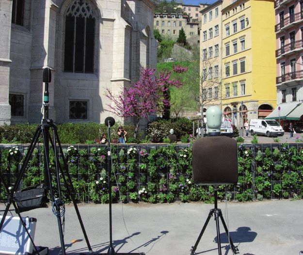
Principles of noise reduction
As sound propagates outdoors from a source, the factors determining the sound level at the receiver
relate to the distance between source and receiver, properties of the medium, air, in which sound
propagates, and properties of the boundary, that is, the ground material and profile, including noise
barriers and other obstacles.

distanc e                                                  influence of ground, wind, and other environmental
In free space, sound from a point source spreads           factors. A similar principle applies to railway noise.
spherically and decays by 6 dB with each doubling of       In general, when making noise mapping calcula-
the distance from the source, whereas sound from a         tions, the whole traffic network has to be considered
line source spreads cylindrically and decays by 3 dB       along with the existing propagation conditions.
with each doubling of distance. Predictions of the
maximum sound levels of road traffic noise are based       MediuM
on a single vehicle as the noise source, whereas predic-   The acoustic properties of the medium of propagation,
tions of the average, or equivalent, sound level (e.g.,    air, relate to meteorological conditions, such as wind
Lden and LAeq,24h, where time-averaged energy is           speed and temperature. The largest effects of such
used) assume the whole length of the road to be the        factors occur when they lead to refraction, that is, the
source. Therefore, the maximum noise level decays by       curving of sound paths. The degree of refraction is
6 dB per doubling of distance from the road, whereas       determined by the wind speed profile and the tempera-
the equivalent level decays by 3 dB per distance dou-      ture variation with height. As a result of downward
bling, assuming a long straight road and insignificant     curving, which may occur in the case of downwind

Principles of noise reduction                                                                                       7
sound propagation (i.e., wind blowing from the direc-        ground were not present. At some other frequencies,
tion of the sound source and toward the receiver) or         the two sound waves reinforce each other, making the
temperature inversion (i.e., increasing temperature          level higher than it would be if the ground were not
with height), the noise levels may increase substantially.   present. For traffic noise propagating above an acous-
Conversely, upward curving, for example, in head-            tically hard ground, such as asphalt, the two sound
wind conditions, may greatly reduce levels compared          waves added together will normally lead to an increased
with situations without such refraction. Refraction          noise level. However, above an acoustically soft ground,
effects usually increase with propagation distance.          such as a lawn, the two waves may cancel each other
    Temperature, humidity, and, to a smaller extent,         out over a relatively broad frequency range, result-
static pressure influence the degree of air attenu-          ing in a lower level than if no ground were present.
ation, that is, the molecular absorption of sound                For shielding structures on the ground, for example,
during its propagation. Air attenuation effects              noise barriers, height is the most important property,
are of importance mainly at high frequencies.                assuming negligible sound transmission through or
    Atmospheric turbulence, in the form of                   around the sides of the barrier. Widening the top of
random fluctuations in wind velocity and tem-                the barrier improves the acoustic effect. Better per-
perature, distorts the sound waves. The effects              formance is generally achieved if the barrier is placed
can be seen as scattering of sound into shadow               near the source or near the receiver. In an inner city
regions and reduction of the strength of both posi-          environment, it may therefore be preferable to use a
tive and negative interference. These effects are            noise barrier relatively low in height if it can be located
of importance mainly at high frequencies.                    near the traffic sources. To improve the performance
    The project has studied several methods that act         of such barriers, the width can be increased and the
on the medium of sound propagation, for example,             materials on the top and faces of the barrier should
planting trees behind barriers to improve barrier            be carefully chosen. The materials should be acousti-
performance in downward refraction situations, plant-        cally soft, and in urban environments, with many
ing a strip of trees along a road or artificially creating   sound reflections, it is crucial to choose acoustically
upward refraction with sonic crystal-like barriers.          absorbent materials. In general, important sound
                                                             reflection can occur from the facades of the urban
Boundary                                                     canyon, from the surfaces of noise barriers, and
In flat terrain, both direct sound from the source and       from the surfaces of vehicle bodies, primarily in the
ground-reflected sound can reach the receiver. The           case of large heavy road vehicles and rail vehicles.
effect of the interaction between direct and reflected           The project has examined several methods that act
sound is called the ground effect. At some frequencies,      on the boundary, including softening hard ground,
direct and reflected sound partly cancel each other out,     roughening flat ground, barrier design, and using
which causes the sound level to be lower than if the         absorbent materials on barriers, facades, and roofs.

8                                                                                 Novel solutions for quieter and greener cities
innovative noise barriers,
using natural and recycled materials
An efficient way to reduce ground transport noise is to block the noise by erecting barriers or other
elements near the source. For example, high noise barriers or earth berms are often constructed
along motorways and railways to protect noise-exposed residents. Such solutions may not work in
dense urban settings because of space limitations, traffic safety considerations, or aesthetic reasons.
However, small barriers, less than 1 m high, can be useful in such situations if properly designed.
Conventional barriers are made of wood, metal, or innovative noise barrier solutions, including low-
concrete. However, alternative materials may be more height barriers, lightweight barriers at bridges,
cost-effective, provide better noise reduction, and vegetated barrier caps, and earth berms of various
improve aesthetic values. Examples include recycled designs. The project also tested a new type of bar-
materials from industries and local communities and rier, called the sonic crystal barrier, which consists of
natural materials such as stones, soil and vegetation. a set of cylinders structured in a way that optimizes
The project developed and evaluated several noise reduction in specific frequency regions.
Innovative noise barriers, using natural and recycled materials 9use of recyc led Materials in noise and elastomeric waste, which can be sourced from the
Barriers construction industry, manufacturing industry, and
Although the technology for manufacturing noise- local community in the form of post-consumer waste.
absorbing barriers from recycled materials has been The acoustical performance of reconstituted
available for many years, road noise barriers continue granulated waste depends on several factors related
to be produced largely from virgin materials, including to the ratio of grains to fibres, type of adhesive, and
concrete, masonry, timber, metal, and acrylic glass. other chemical additives used in the consolidation
The most common noise barrier systems process. Common characteristics of recycled poly-
that include recycled materials use wood-fibre- meric waste that can be acoustically optimized include
reinforced concrete, granulated rubber tyre open porosity, flow resistivity, and stiffness. For
infill, recycled plastic lumber, or a combination sound insulation applications, we recommend mate-
of a retaining recycled shell manufactured from rial with a relatively low open porosity, a relatively
PVC waste with a porous mineral wool core. high density, and a relatively high damping ratio.
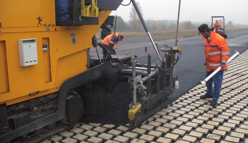
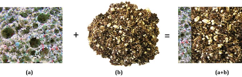
To improve on existing technologies, the project Below are examples of how recycled waste may be
has developed a new cold process to produce highly used: (1) to increase sound absorption and soil reten-
porous media with a controlled pore size distribu- tion in vegetated noise barriers, and (2) for the con-
tion and a controlled proportion of open, intercon- struction and vegetation of a high-density barrier.
nected pores in a range of pore size distributions. A major drawback of conventional porous
These materials are based on granulated polymeric absorbers is their poor performance in the low-
Top row – Recycled material
used for sound absorption and
soil retention applications:
(a) low-density consolidated
material made from recycled
waste, (b) low-density soil, and
(a + b) combination of low-
density consolidated material
and low-density soil. Bottom
row – Recycled material used in
sound transmission applica-
tions: (a) high-density barrier
material made from recycled
waste, (b) low-density soil,
and (a + b) high-density panel
placed behind low density soil.
10 Novel solutions for quieter and greener citiesfrequency range where the acoustic wavelength soil developed in the project displays a frequency-
is greater than the thickness of the porous layer. dependent acoustic absorption coefficient close to
To improve the low-frequency noise absorption of that of a layer of glass wool of the same thickness.
porous layers, it is common to combine several lay- The presence of leaves with a large surface area can
ers of materials homogeneous in pore structure. noticeably improve the acoustic absorption of hard soils
Ideally, a porous noise-absorbing material should across a broad frequency range. The enhancement of
have an impedance close to that of air to prevent the acoustic absorption depends on the type of plant,
reflections, while offering high internal acoustic leaf angle, amount of foliage on the plant, and total
attenuation. These two requirements are difficult to leaf area in a unit volume; the absorption coefficient of
achieve in homogeneous materials, and can be more a plant with a larger leaf area exhibits less frequency
easily achieved in stratified materials. Samples of dependence in the case of a soil with a lower density.
recycled polymeric material with a stratified pore A green wall containing low-density soil provides
structure were produced in the project to improve an alternative to more conventional types of acoustic
the noise absorption capability of conventional homo- treatment, particularly in the low- and high-frequency
geneous porous layered materials by 20–40%. ranges. The key concept is to provide a panel contain-
ing a stable porous granular medium, manufactured
use of soil and Pl ant systeMs in from waste materials (from the textile, construction,
noise Barriers and manufacturing industries), that supports plants
The project’s research into the noise absorption capabil- that can provide acoustic absorption, water retention,
ity of soil and plant systems suggests that the acoustic and local climate modification via plant transpiration.
absorption of soil is controlled largely by the type of Below is an image of the construction principle and
soil and the amount of moisture. A layer of low-density an application in the vicinity of a historical building.
A vegetative wall: composition
(left); installation (right).
Innovative noise barriers, using natural and recycled materials 11Low-height noise barrier
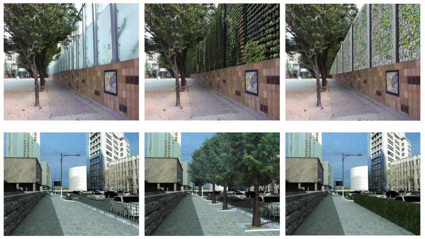
low-height noise Barriers 9 dB(A) compared with an untreated situation, in a
Low-height noise barriers are small barriers whose region 2–50 m behind the barrier, the height of the
width and height do not exceed 1 m, erected to receiver being 1–5 m. The noise reduction can decrease
reduce rolling noise from cars or trams. Such barri- by a few decibels in the case of a canyon street, but
ers can be used in dense urban areas to protect pave- increase by a few decibels if a second similar low-height
ments and benches near roads or rails from noise. barrier is constructed between the two lanes of the
Several configurations of low-height barriers road. For trams, the extra noise reduction obtained
(e.g., using stone gabions or vegetation) have been by adding a second central barrier is approximately
studied in the project. We demonstrated that low- 8 dB(A) compared with a single barrier beside the rail,
height barriers can protect pedestrians, cyclists, which reduces the noise by approximately 12 dB(A).
and nearby residents from noise, provided that the In the case of a 1-m-high standard gabion
barriers are well designed and located near the made of 15–20-cm-dimension stones along a two-
sound source. This is possible in situations with lane urban road, the acoustical noise reduction is
limited traffic speed, such as in city centres. 3–8 dB(A) compared with an untreated situation,
In an open space, a 1-m-high straight barrier made for a receiver located 2–50 m behind the barrier and
of a 40-cm-wide mixture of natural fibres and mineral 1–5 m above ground. Replacing stones with porous
materials, with a rigid core, installed along a two-lane clay will attenuate the sound by an extra few dB(A).
road can potentially reduce road traffic noise by about If we consider rigid sonic crystals combined
12 Novel solutions for quieter and greener citieswith a low-height straight barrier installed along up to 8 dB(A) compared with an untreated situation, in
a two-track tramway, the noise reduction is up to the case of both urban roads and tramways, for a receiv-
10 dB(A) compared with an untreated situation, for er located 2–50 m behind the barrier and 1–5 m above
a receiver located 2–50 m behind the barrier and ground. Low-height berms function along high-speed
1–5 m above ground. Adding a 2-cm layer of hemp railways and motorways as well, provided the infra-
concrete to the surface of the cylinders leads to addi- structure is significantly embanked. With a 4-m-high
tional noise reduction of approximately 7 dB(A). embankment, the acoustical noise reduction is up to
For grass-covered low-height berms (i.e., 1 m high 7 dB(A) compared with an untreated situation, for a
and 1 m wide) with slopes containing large irregularities receiver located 2–50 m behind the barrier and 2–10 m
up to 25 cm in depth, the acoustical noise reduction is above ground for the train and 2–5 m for the motorway.
Height [m]
4
Overall decibel reduction (dB(A)) compared with the same
2 situation without a barrier, calculated for a 1-m-wide and
1-m-high gabion barrier made of 15–20-cm-dimension stones
0
(top) and porous clay (bottom), in the case of a two-lane
4 urban road.
2
0
-1 1 3 5 7
distance [m]
Height [m]
10
11
10
reduction
9
Noise
8
7
0 6
5
4
10 3
2
1
0
increase
-1
Noise
-2
-3
0
-10 0 10 20 -10 0 10 20
distance [m]
Overall decibel reduction (dB(A)) compared with the same situation without a berm, calculated for a low-height stair-case shaped
earth berm close to a high speed train (left) or motorway (right) at a 4 m high embankment (top) or on flat terrain (bottom).
Innovative noise barriers, using natural and recycled materials 13Lightweight vegetated barriers at bridge
light weight vegetated Barriers multiple-reflected sound energy between the bar-
at Bridges rier and the tram body. This type of installation can
Traffic travelling over bridges in urban areas may promote walking and bicycling by ensuring accept-
expose pedestrians and cyclists in areas below the able soundscape quality along the travelling path.
bridges to noise. Thin rigid 1-m-high noise barriers
along the edges of such bridges may reduce noise refr active sonic c rystal
levels in the receiving areas by up to 4 dB(A) in the Refractive graded-index sonic crystal noise barriers
case of a four-lane motorway, and by up to 10 dB(A) for (GRIN SC) are a class of sonic crystal barriers with
a two-track tramway, without disturbing the drivers’ cylinders placed parallel to the ground surface. By
view from the bridge. When the low-height barrier spatially varying the properties of the barrier, which
is made of a rigid core covered with thick absorptive in the simplest case consists of air and acoustically
material of natural fibres and minerals, the noise hard cylinders, sound waves propagating through
reduction may reach 5 dB(A) and 15 dB(A) for the the barrier can be redirected upwards (i.e., upward
motorway and tramway, respectively. The high reduc- refraction). Parameters such as the cylinder radius,
tion for the tramway is due mainly to the absorption of spacing between cylinders, and barrier formation (i.e.,
5 10
Height [m]
5
−0
0 −5
−2 0 10 20 30 40
Distance [m]
Overall decibel reduction (dB(A)) compared to the same situation without a graded index sonic crystal barrier. Sound pressure levels are predicted
for a 1-m-tall graded-index sonic crystal (GRIN SC) barrier of 1 m2 cross sectional area. A two-lane road with lightweight vehicles driving at
50 km/h is modelled. The green regions extending horizontally behind the structure shows where significant noise reduction takes place.
14 Novel solutions for quieter and greener citiesStaircase shaped earth berm
the outer shape of the structure) influence the bar- sense of openness is preserved and berms can also
rier’s performance. A beneficial aspect of GRIN SC be planted, which can improve visual attractiveness
noise barriers, within the targeted frequency range, and increase their sound absorption. Other advan-
is their lower reflectance (i.e., reflected energy in the tages are a very long lifetime, limited maintenance
direction of the source) than that of traditional noise cost, and few or no graffiti problems. Furthermore,
barriers. GRIN SC noise barriers only function as excess material from other locations, such as soil and
refractive structures up to certain frequencies, above stones from construction work, can be recycled by
which other physical properties of the barrier exert a constructing berms for noise-protection purposes.
noise-mitigation effect for the receiver. The net noise While a conventional noise barrier’s efficiency
reduction, expressed in dB(A), thus comprises the effect decreases considerably in downwind conditions (i.e.,
of a combination of noise-controlling mechanisms. blowing from source to receiver), berms are less
A 1-m-tall GRIN SC, installed along a two-lane road, sensitive to the action of such winds. With decreas-
can reduce noise by 4 dB(A) at ear height, at a mini- ing berm slope angle, the negative action of the wind
mum horizontal distance of 15 m from the barrier. decreases significantly. It has been estimated that,
in many cases, the average wind effect can be under
vegetated Barrier caPs 1–2 dB(A) for berms with a slope of 18 degrees, or for
Existing noise barriers can be improved by planting steeper slopes with a flat top. Although noise bar-
vegetation along the top edge, which increases sound riers can be placed closer to a source than berms
attenuation during noise propagation. Most conven- of the same height and may be preferred for this
tional barriers have “caps” (or crowns) made of porous reason, it should be borne in mind that this may be
wood cement. Replacing these with caps of planted at the expense of greater wind-induced deteriora-
growing medium (made of natural fibres and min- tion in acoustical performance. When berms are
eral materials) can substantially improve the acoustic sufficiently acoustically soft, similar shielding can
performance. For a pedestrian or cyclist moving 1 m be obtained by a wall and a berm if the elevation of
behind the barrier, the acoustical noise reduction due the top of the wall and of the berm are the same.
to a 1-m-wide element is 8–12 dB(A), compared with an Predictions indicate that earth berms with non-flat
uncapped straight barrier of the same overall height. surfaces on their slopes and top can reduce noise more
than can conventional, smooth trapezoidal berms. On
e arth BerMs flat rural terrain, this change in berm geometry from
Although berms require more space than do bar- flat to stepped in profile can reduce noise by 4 dB(A)
riers, they offer many non-acoustic benefits. The compared with a conventional 4-m-high berm.
Innovative noise barriers, using natural and recycled materials 15Multiple rows of trees
in an open field
trees, shrubs, and bushes
Assigning sufficient space for vegetation is important in urban planning. At the same time, sound
waves can be influenced when propagating through vegetation. The well-planned use of vegetation
can achieve useful road traffic noise reduction.
The interaction between noise and vegetation includes incident on a twig or leaf will change its propagation
direct effects such as reflection, diffraction, scatter- direction, and is then scattered again by nearby plant
ing, and absorption by plant elements such as stems, elements. As a result, part of the sound energy will
branches, twigs, and leaves. In addition, develop- leave the direct path between source and receiver, yield-
ing acoustically soft soil underneath vegetation (by ing lower sound pressure levels at that receiver. Numeri-
means of plant root action and humus layer forma- cal models with different degrees of complexity have
tion) and the changed micro-climatology provided been developed in the project to simulate this effect.
by canopies can also lead to noise reduction. Leaves typically vibrate at sound frequencies
Sound levels are reduced by interacting with near 2–4 kHz. At these frequencies, large sound
plant material in two main ways: sound can be pressure level differences over a leaf can be mea-
redirected by means of reflection, diffraction, or sured. Measurements in controlled laboratory condi-
scattering, or sound can be effectively absorbed tions indicate more noise reduction with increas-
by the plant material. Part of the absorption is ing leaf area density, leaf size and leaf weight.
caused by the damped vibrations of leaves. Also the orientation of the leaves relative to the
In vegetation, multiple scattering occurs. Sound incident sound waves plays an important role.
16 Novel solutions for quieter and greener citiestrees in street canyons and without leaves indicate that leaves increase rever-
Along urban roads flanked by tall buildings there are beration mainly at frequencies above 2 kHz, though
multiple reflections between building facades and these reverberation is still present in the absence of leaves.
greatly increase street noise levels, for example, during Scale-model experiments suggest that trees may
the passage of a car. Planting trees near the road might reduce sound propagation along streets, provided that
contribute to multiple scattering of sound by branches, the receiver is sufficiently far from the source. The
twigs, and leaves in tree canopies. The longer this effect will be most noticeable at higher storeys, where
reverberation inside the tree canopy, the less energy will noise reduction is expected in the high frequency part
remain in the sound wave as a result of the increasing of the sound spectrum. On the other hand, increased
distance travelled and sound energy absorbed. Impor- downward scattering may be observed for receivers
tantly, part of the sound energy will be redirected and present below the bottom of the canopy. Overall, the
will leave the street in an upward direction, which reduction in noise levels due to trees in street canyons
contributes to noise reduction at the street level. is expected to be small and no more than 2 dBA.
Results of field measurements indicate that tree
reverberation exerts an influence only on frequencies MultiPle rows of trees in oPen fields
above 1 kHz. At 4 kHz the reverberation time can be as A single row of trees along a road beside an open field
long as 0.34 s. If the tree canopy is sufficiently large, will not significantly affect traffic noise levels, though
the internal reverberation can be longer still. Mea- positive effects can be expected when there are multiple
surements made near the same deciduous tree with rows. The presence of above-ground biomass and the
In-situ transmission measurements of a hedge
(top left), absorption measurements of leaves and
substrate in a reverberant chamber (top right),
absorption measurements of leaves in an impedance
tube (bottom left), vibration measurements with a
doppler-vibrometer of a single leaf under acoustic
load in an anechoic chamber (bottom right).
Trees, shrubs, and bushes 17soft soil developing under vegetation together reduce tant at very high frequencies, however, only slightly
road traffic noise. Both the trunks and low-growing influencing total A-weighted road traffic noise levels.
vegetation contribute to the noise reduction effect of a Important design parameters in vegetation belts are
green belt. The canopy layer, on the other hand, could tree spacing, trunk diameter, length and depth of the
have a small negative effect when both source and belt, the choice of planting scheme, and shrub bio-
receiver are located underneath because of downward mass density. Above 2 m, tree height is usually not a
scattering by the canopy and downward reflection at relevant parameter in typical traffic noise situations.
the bottom of the canopy. This effect becomes impor-
Snapshots of sound field distribution at three moments during propagation through an open field (left) and a tree belt (right). An acoustic
pulse is initially excited (upper row) and the sound field development during propagation is shown (middle and bottom row). The colour
scale is arbitrary: orange and yellow indicate zones of high sound pressure levels, green intermediate levels, and blue low levels. The multiple
scattering processes in the different layers of the tree belt are clearly visible in the right-hand diagrams.
Sound pressure level [dB]
80
Sound-pressure-level spectra at 40 m distance from a two-lane road
Without abatament
25 m wide tree belt (5% heavy and 95% light vehicles, travelling at 50 km/h) predicted
70 for a 1.5-m-high receiver located behind a 25-m-wide and 75-m-long
tree belt, equidistant from the belt ends (green), or at the same
60 position with grassland between road and receiver (black). The tree
belt starts near the border of the road. A slightly disordered planting
50 grid is modelled, starting from a regular grid with a spacing of 1 m
along the road length axis, and 2 m normal to it. The diameter of
40 the trees modelled was 16 cm, leading to a trunk cover fraction of
1%. Predicted insertion loss of tree belt: 7 dB(A).
30 Frequency [Hz]
63 125 250 500 1000 2000 4000
18 Novel solutions for quieter and greener citiesTrees to improve noise
barrier performance
Tree spacing along the length of the road is a Pl anting trees to iMProve noise
key parameter, and should be as close as practically Barrier PerforManc e
possible. Pseudo-random planting schemes should be Vegetation influences the local micrometeorology, which
encouraged, that is, the trees are planted following a in turn influences sound propagation. Of particular
regular grid, but with small and random deviations. interest for sound propagation are changes in tempera-
Variations in trunk diameter are also positive when it ture profiles, relative humidity, and wind speed profiles.
comes to reducing road traffic noise levels. Tree species A 50 m wide vegetation zone significantly limits
should be selected that can develop high stand densities the build-up of a ground-based temperature inversion
and large trunk diameters. Introducing open zones layer at night compared to an open field. The presence
(not near the borders) does not significantly reduce the of a temperature inversion layer at low heights in the
performance of the tree belt. Increasing the spacing atmosphere can otherwise strongly increase sound pres-
normal to the length axis of the road, and introducing sure levels from a road due to downwardly bent sound.
open zones, is a practical way to achieve a realistic During daytime, the typical temperature profiles as
(averaged) trunk volume, without negatively affecting found inside a strip of a forest results in a slightly worse
the noise shielding. Calculations reveal that a narrow shielding compared to sound propagation above an open
(approximately 15 m wide) but optimized vegetation field. The gain in noise shielding at night is expected
belt along a road is equivalent to the shielding of a to outweigh the reduced performance during daytime.
1–1.5-m-high conventional concrete noise wall placed Vegetation can be designed to improve the micro-
directly near the road, that is, about 5–6 dB(A). meteorological conditions near noise walls in wind.
Wind negatively affects noise shielding behind non-
Trees, shrubs, and bushes 19aerodynamically designed obstacles, such as a row of cal noise walls, strongly limit negative wind effects
houses or a vertically erected noise wall. Such refrac- compared to noise walls of the same height. The
tion effects can be quite dramatic, especially in the use of trees near berms is therefore not advised.
case of high wind speeds for downwind receivers.
This effect occurs immediately behind a barrier, in shruBs , Bushes , and hedges
the zone where we would expect high shielding. Significant noise reduction by planting shrubs, bushes,
The canopy of trees provides wind shelter, so plac- and hedges, requires high above-ground biomass
ing a row of trees behind a noise barrier will help to densities. The presence of the shrubs themselves
reduce these wind effects. Specific canopy designs is expected to be responsible for a maximum of a
should be applied based on the zone downwind where few dB(A) of noise reduction in typical road traf-
optimal improvement is wanted and on the type of fic applications. Note, however, that this effect can
barrier (i.e., a single noise wall or noise walls on either complement the other effects operating in a vegetation
side of the road). Ideally, canopies should be dense, belt, such as the presence of tree trunks and the soil
making coniferous trees particularly suitable. At a effect. The soil effect is expected to play a major part
short distance downwind, the shielding that was lost in the noise reduction caused by a belt of shrubs.
by wind action can be largely recovered when the bot- Hedges yield road traffic noise shielding between
tom of the canopy starts near the barrier top. Leaving 1 dB(A) up to a maximum of 2–3 dB(A). Hedges should
a gap between the canopy and a single barrier leads be sufficiently thick and very dense (internally). In
to maximum improvements further downwind. addition, there should be sufficient biomass close to the
Near steeply sloping berms, trees do not improve ground. This is needed to prevent sound propagating
shielding in wind. Gradually sloped berms, which underneath the hedge. This is especially important for
are more aerodynamic in shape than are verti- rolling noise, which is generated close to the ground.
Sound-pressure-level spectra at 100 m distance from a four
lane highway (15% heavy and 85% light vehicles, travelling at
Sound pressure level [dB]
80 100 km/h) predicted for a 1.5-m-high receiver in strong downwind
Without abatament for situations without noise barrier (black), with a 4-m-high barrier
Barrier
70
Barrier and trees near the highway (grey), and with a dense row of trees positioned
directly behind the 4-m-high barrier (green). The canopies extend
8 m above the top of the noise wall. A gap of 1 m between barrier
60
top and the bottom of the crown of the trees is reserved to improve
the positive effect. Due to the complex shifts in interferences in the
50
acoustic shadow zone, caused by changing the wind fields, a slightly
worse situation is possible in some frequency intervals. Note that in
40
the current simulation, downward scattering by the tree crowns has
not been accounted for. Predicted insertion loss: 9 dB(A) for barrier
30 Frequency [Hz]
63 125 250 500 1000 2000 alone and 13 dB(A) for barrier combined with trees.
20 Novel solutions for quieter and greener citiesNoise reduction by means of ground treatments Ground treatments aim to reduce noise at the receiver by exploiting the ground effect, that is, the effect of destructive and constructive reflections of sound from the ground. Such treatments include creating artificial ground roughness by using small hard blocks or by making grooves or pits, burying resonant cavities in the ground or road surface, introducing soft strips or patches (e.g., gravel-filled trenches), or changing the type of ground or groundcover (e.g., planting vegetation with favourable acoustic properties). Over acoustically hard ground, such as a non-porous pressure of road-traffic noise, compared with no ground, concrete or asphalt, destructive interference generally which corresponds to an increase of 6 dBA. How- occurs at frequencies that are too high to reduce the ever, over acoustically soft ground, such as grassland, overall sound level. For example, at 1.5 m height and destructive interference generally attenuates the sound distances of 10 m or more from a road, the presence of more than would be expected by simply increasing the acoustically hard ground more or less doubles the sound distance and from atmospheric sound absorption. Noise reduction by means of ground treatments 21
roughness eleMent configur ations                                                        If the roughness elements are distributed ran-
on hard ground                                                                      domly, the ground-effect spectrum displays a single
Introducing small objects on smooth, acoustically                                   destructive interference pattern resulting in excess
hard surfaces changes the sound reflection, thereby                                 sound attenuation over a broad range of frequencies.
reducing the frequencies at which there is destruc-                                 If the spacing is regular, then there can be additional
tive interference. The acoustical effects of an array                               destructive interference, but affecting narrower ranges
of such roughness elements depend on their mean                                     of frequencies, than is produced by random roughness
height, mean spacing, cross-sectional shape, total                                  of the same height and mean spacing. As far as the
array width, and whether the configuration is random                                overall reduction of traffic noise is concerned, there is
or periodic. One can design a roughness configura-                                  no clear advantage to using periodically rather than ran-
tion 0.3 m high and 2 m wide that can help reduce                                   domly spaced roughness elements. However, periodic
traffic noise by at least 3 dB, compared with smooth,                               arrangements may be preferred for their appearance
acoustically hard ground, at 10 m from the road, while                              and ease of construction or sound perceptual reasons.
a 3-m-wide configuration of the same height reduces                                      Below are two examples of roughness configura-
the noise by at least 7 dB(A) at 50 m from the road.                                tions made from ordinary household bricks. The con-

                                                                                                     An array of nine parallel walls made from
                                                                                                     1440 household bricks loosely stacked on
                                                                                                     edge (left). The same number of bricks
                                                                                                     made into a square-cell lattice (right).

Sound pressure level [dB]                                                           Sound-pressure-level spectra from a two-lane urban road (5%
80                                                                                  heavy and 95% light vehicles, travelling at 50 km/h) predicted
                                               Without abatament
                                               Walls                                for a 1.5-m-high receiver located 50 m from the nearest traffic
70                                             Lattice
                                                                                    lane: (i) without treatment (black), (ii) with a 3.05-m-wide
                                                                                    parallel-wall array consisting of 16 identical 0.05-m-thick and
60
                                                                                    0.3-m-high acoustically hard walls with centre-to-centre spac-
50                                                                                  ing of 0.2 m (green), and (iii) with a 0.3-m-high, 1.53-m-wide
                                                                                    acoustically hard square lattice arrangement (grey). The
40                                                                                  receiver is assumed to be located along the centre line of the
                                                                                    arrays, and both arrays are assumed to start 2.5 m from the
30
                                                                                    nearest traffic lane. Predicted insertion loss: 7 dB(A) for walls
                                                                   Frequency [Hz]   and 6 dB(A) for lattice.
20
       63       125         250   500   1000      2000     4000

22                                                                                                             Novel solutions for quieter and greener cities
figurations were constructed from the same number of a larger land area. Compared with hard smooth ground,
bricks, but the parallel-wall configuration (left) is nearly a 16-m-wide series of wall clusters of varying heights
twice as wide as is the lattice configuration (right). arranged in a fractal pattern is predicted to reduce the
Lattice configurations half the width of parallel- sound level that would occur over smooth hard ground
wall arrays of the same height are predicted to produce by 11 dB(A) for a 1.5 m receiver 50 m from a two-lane
comparable noise reduction. If there are no adverse urban road (5% heavy and 95% light vehicles, travel-
meteorological effects and the array length is sufficient, ling at 50 km/h). This is 2.5 dB(A) more than would be
then, for a given receiver height, the noise reduction obtained using a 16-m-wide array of regularly spaced
produced by roughness arrays is predicted to decrease identical 0.05-m-thick walls of the same height.
only slightly with increased distance from the road Sometimes bunds or berms rather than fence-
beyond 50 m. For example, the insertion loss predicted type barriers are used for noise control. If the berms
for a 3.05-m-wide, 0.3-m-high lattice is predicted to are constructed with compacted soil surfaces, the
decrease by less than 1 dB(A) (i.e., from 7.1 dB(A) deliberate introduction of roughness in the form of
to 6.2 dB(A)) at 50–250 m from the road. Another parallel walls or grooves can improve their acoustical
advantage of a lattice configuration is that its acoustical performance. For example, a 15-m-wide trapezoidal
efficacy is less dependent on the azimuthal source– berm (4 m high with a 3-m-wide top) located next to
receiver angle than is that of the parallel-wall array. a four-lane motorway can reduce the average noise
The predicted noise reduction is lower if the propor- by a substantial 18 dB(A) in a region extending up
tion of heavy vehicles (whose engine noise sources are to 20 m behind the receiver-side edge of the berm.
positioned higher than in cars and produce more low- Nevertheless, constructing closely spaced, narrow
frequency energy) is greater and if there are traffic lanes deep parallel grooves (0.2 m deep, 1.25 cm wide, 2.5
farther from the roughness configuration. Nevertheless, cm centre-to-centre spacing) on the top of the berm is
45 m from the edge of a four-lane motorway, carrying predicted to reduce noise by a further 7 dB(A). This is
15% heavy and 85% light vehicles travelling at 70 km/h, equivalent to the noise reduction resulting from a 1-m
a 15-m-wide array of 26, 0.247-m-high parallel walls increase in the height of the smooth berm. A further
with equilateral triangular cross-sections (i.e., wedges) noise reduction of up to 3 dB(A) is predicted if all sides
starting 1 m from the nearside road edge is predicted of the berm are roughened in the same manner.
to reduce noise by 8.5 dB(A) and 3 dB(A) for receivers Experiments and simulations have demonstrated
at heights of 1.5 m and 4 m, respectively. Although that the noise insertion loss due to low parallel wall
the cross-sectional shape of the roughness elements and lattice configurations would be unaffected and,
has an effect, the predicted increase in noise reduc- indeed, enhanced by placing small amounts (up to 10
tion that would result from using wedges rather than cm deep) of gravel, sand, or soil in the gaps. In prin-
a 0.3-m-high rectangular low wall of the same cross- ciple, it would be possible to grow plants between the
sectional area in this motorway case is less than 1 dB. elements. In addition, creating a 0.5-m-wide pathway
Greater noise reduction than obtained using regu- through a roughness configuration would not sig-
larly spaced identical parallel low walls is achievable nificantly reduce its noise reduction performance.
using clusters of walls of varying heights. However, Roughness-based noise reduction is also appro-
such profiles require that the roughness array be wider priate for mitigating railway noise. As in the case of
than it would be without clusters and therefore occupy road traffic noise, the noise reductions caused by the
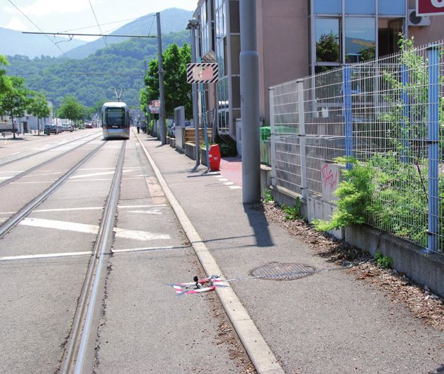
Noise reduction by means of ground treatments 23Roughness-based noise reduction using low parallel walls close to a tramway
wall systems are predicted to decrease as the receiver between the road and a receiver. Similar reductions
height increases. For example, a 3.05-m-wide con- of between 2 and 6 dB(A) will occur if up to 50% of
figuration of 16 parallel walls starting 1 m from the hard ground is replaced with gravel near to a railway.
nearest track is predicted to reduce railway noise by Although multiple relatively narrow strips may be
more than 6 dB(A) at a 1.5-m-high receiver 50 m from preferred for aesthetic or practical reasons, they do not
the edge of the track. A configuration of two, four-wall achieve any greater noise reduction than does a single
clusters near the rails is predicted to reduce railway strip of the same total width. Moreover the number of
noise by 6–7 dB(A) if the configuration consists of strips within a given area of ground is not predicted
acoustically hard walls and by 7–8 dB(A) if the con- to have much influence on the noise reduction. For
figuration consists of slightly soft walls. Any of the the considered geometry and the use of gravel, no
proposed roughness-based treatments can be recessed increase in the noise insertion loss is predicted if the
in trenches or drainage gullies up to 0.3 m deep but width of a single strip is increased beyond 25 m. On
their insertion loss is thereby reduced typically by 3 dB. the other hand, the creation of hard strips in otherwise
acoustically soft ground offers the added functionality
gr avel striPs and Patc hes of providing footpaths and cycle paths, albeit neces-
Introducing a single strip or multiple strips of an sitating a wider treatment strip to achieve the same
acoustically soft material such as gravel can also reduction as a single soft strip of a given width.
reduce traffic noise in cases where otherwise there is Some improvement in performance can be
hard ground, such as non-porous asphalt or concrete. expected if the strips are distributed in patches,
Predictions suggest a reduction potential of 3–9 dB(A) for example, in a “chequerboard” arrangement,
at a height of 1.5 m, 50 m from a two-lane urban road since this would reduce the dependence of the
with either a single wide strip or several narrow strips noise reduction on the azimuthal angle.
of gravel alternating with equally wide “hard” strips
24 Novel solutions for quieter and greener citiesSoft strips and patches
ground and ground cover tant parameter when selecting grass is the ease with
Softening the ground between a source and a receiver, which air can penetrate the ground surface, that is,
for example, replacing asphalt with grass, can sub- flow resistivity. For grounds of comparable poros-
stantially reduce the noise from a road. The introduc- ity, higher noise reduction is expected with lower
tion of a 45-m-wide area of any type of soft ground flow resistivity. Ground that is compacted as a result
to replace hard ground starting 5 m from the nearest of frequent mowing, rolling, or passage of wheeled
traffic lane will reduce noise levels by at least 5 dB(A), equipment is likely to have a higher flow resistiv-
and up to 9 dB, for a 1.5-m-high receiver 50 m from ity and thereby reduce noise to a lesser degree.
the road. Similar reductions, 3–5 dB(A), will occur The difference between types of soft ground shown
at the 1.5 m high receiver at 50 m if soft ground is in the photos below is predicted to result in up to a
introduced in place of hard ground near to a railway. 3 dB(A) difference in the sound levels for a 1.5-m-high
The type of groundcover, for example, type of receiver 50 m from a road as long as the soft ground
grass, can also influence the ground effect. An impor- extends from near (i.e. 5 m) the road edge to the receiver.
Sound pressure level [dB]
80
Without abatament
Compacted grass
Meadow
70
60
50
Two types of grass-covered ground. Sound-pressure-level spectra predicted for
a 1.5-m-high receiver located 50 m from the nearest traffic lane (5% heavy and
40
95% light vehicles, travelling at 50 km/h) for compacted grass (grey), meadow
(green) and hard ground (black) between road edge and receiver. Predicted Frequency [Hz]
30
insertion loss: 5 dB(A) for compacted grass and 8 dB(A) for meadow. 63 125 250 500 1000 2000 4000
Noise reduction by means of ground treatments 25c roPs Buried resonators Crops may yield extra attenuation of traffic noise in A resonator consists of a hollow container with a neck, addition to that due to the soft ground effect. Crops are rather like a bottle. The resonance frequency can be characterized by the leaf area per unit volume (canopy tuned and depends on the neck’s cross-sectional area index) and by the mean leaf size. For dense maize, the and length and on the container’s volume. An array of leaf area per unit volume is 6.3/m and the mean leaf buried resonators in an otherwise acoustically hard area width is 0.0784 m. For winter wheat, the correspond- can reduce noise levels. For example, a 4-m-wide strip, ing values are 30/m and 0.012 m, that is, although the perhaps of hard shoulder, containing a square array of winter wheat is assumed to have higher foliage area per resonators with centre-to-centre spacing of 6 cm and unit volume, it has smaller leaves. The overall sound neck openings of 1 cm tuned to 350 Hz is predicted attenuation can be calculated from the sum of that due to reduce the noise level for a 1.5-m-high receiver to the ground effect and that occurring along those 40 m from a two-lane urban road (5% heavy and 95% parts of the direct paths from the vehicle sources to the light vehicles, travelling at 50 km/h) by 2–3 dB(A). receivers passing through the crop. Example results It is possible to combine acoustic resonators of such calculations indicate that the combination of with porous road surfaces. Buried resonators affect high-flow-resistivity ground and a small-leaf crop has the acoustical properties of a porous asphalt road in little merit with respect to noise reduction. On the two ways: (a) they attenuate sound during propaga- other hand, combinations of low-flow-resistivity ground tion over the road surface, and (b) they reduce the and dense, large-leaf crops are predicted to attenuate sound amplification associated with the geometry the sound by 9–13 dB(A) for a 1.5-m-high receiver 50 of the tyre–road contact (i.e., the “horn effect”). m from the road, of which 1–5 dB(A) is contributed by The sound absorption coefficient measured the crops. The corresponding predicted total attenu- perpendicular to the surface of twin-layer porous ations for a 4-m-high higher receiver are 2.5–7 dB, of asphalt with a layer thickness of approximately 7 cm which 0.3–4.5 dB(A) are contributed by the crops. has pronounced maxima at approximately 600 Hz A resonator covered with porous asphalt (left) and the construction of a resonator-improved porous asphalt (right). 26 Novel solutions for quieter and greener cities
and 1800 Hz. Although the maxima decrease in years under traffic have indicated that the resonators
amplitude with decreasing angle of incidence, the reduce the sound pressure level by the original amount
frequency dependence of the absorption coefficient (versus without resonators) of approximately 3–4 dB(A)
could still be improved by inserting resonators for passenger cars and approximately 2 dB(A) for heavy
tuned to 1 kHz. In this way, buried resonators can trucks for a 1.2-m-high receiver at 7.5 m distance. This
improve the noise reduction capability of new twin- means that resonator-improved porous asphalt can
layer porous asphalt by approximately 3 dB(A). yield useful traffic noise reduction not only immedi-
Pass-by measurements made on a test section of ately after construction but for at least three years.
a highway containing buried resonators after three
Sound pressure level [dB]
80
Sound-pressure-level spectra (left) and maximum
Porous asphalt
Porous asphalt A-weighted sound pressure levels (below) from
& resonators
pass-by measurements over porous asphalt with and
70
without buried resonators (light vehicle rolling noise
at 100 km/h, for a 1.2-m-high receiver located 7.5 m
60 from the road). The addition of resonators increases
the insertion loss with approximately 3 dB(A).
50
40 Frequency [Hz]
125 250 500 1000 2000 4000
85
A-weighted sound pressure level [dB(A)]
Porous asphalt
Porous asphalt and buried resonators
80
75
70
65
100 105 110 115 120 125 130 135 140
Speed [km/h]
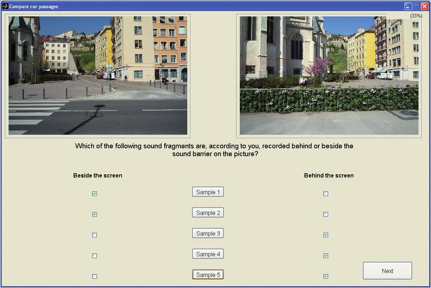
Noise reduction by means of ground treatments 27Vegetation in urban streets and courtyards vegetation in urban streets, squares, and court yards Vegetation can potentially reduce noise levels in situations in which multiple reflections from facades lead to increased sound levels, for example, in street canyons, courtyards and urban squares. The acoustic effects of vegetation in such situations are related to three mechanisms: (1) sound absorp- tion, (2) sound diffusion, which occurs when a sound wave impinges on the vegetation and is then reflected back, and (3) sound transmission when a sound wave is passing through the vegetation. Increasing boundary absorption can substantially effect of vegetation will be greater, even when the diffu- attenuate noise. Vegetation with soil applied on building sion capability is relatively low. In addition, the absorp- facades can have such effect, and this could be greatly tion and diffusion effects are useful for reducing the enhanced in urban areas since there are multiple reflec- negative effects of ground reflections that often occur tions. Compared with boundaries reflecting sound in in outdoor sound propagation above hard ground. one direction, boundaries reflecting sound diffusely in many directions, such as caused by vegetation, may vegetated roadside facades affect the total sound field. When there are multiple In urban canyons vegetation can be placed on the reflections as typically for urban areas, the diffusion building facades. Climbing plants or green walls 28 Novel solutions for quieter and greener cities
Vegetation in street canyon

that consist of plants, growing medium packed into
geotextiles or pots and a supporting structure may be
applied. The noise reduction potential of vegetation
including substrate placed on street canyon facades
is affected by canyon width, vegetation and substrate
placement, and receiver position. The noise absorp-
tion effect is more efficient in narrower canyons and
the extra attenuation provided by placing vegetation
with substrate or other absorbing surfaces on facades
increases with greater source–receiver distance. Add-
ing vegetation to facades in traffic-bearing streets is
more effective for higher receiver positions. Vegeta-      Vegetated facades in urban squares
tion absorbs and scatters sound mainly at mid and
high frequencies, so the acoustic effectiveness of         vegetated facades in urBan squares
greening facades will be lower at low frequencies.         As in the case of urban streets, the noise reduction
    To illustrate the effect of facade vegetation, noise   potential of vegetated facades is greater for narrower
reduction was calculated for a single street with          squares and for receivers situated further from traf-
19-m-high facades on both sides, assuming non-             fic sources. Note that if traffic runs through the
vegetated facades with very low noise absorption.          square itself, the vegetation will reduce the noise
The acoustic treatment consisted of a supporting           by less than if the traffic runs on a side street.
system, soil, and vegetation. The calculated predic-            The effect of green wall treatments on facades was
tions suggested that a noise reduction of 2–3 dB(A)        predicted for a square with a street on one side, assum-
may be obtained at a height of 1.5–4 m if all facades      ing non-vegetated facades with very low noise absorp-
are covered with vegetation, compared with non-            tion. Averaged over 1.5-m-high receivers, a reduction of
vegetated facades. If only the upper halves of the         3 dB(A) is achieved with vegetation covering all facades
facades are covered with vegetation, the reduction is      in the square and the adjoining street. If vegetation is
approximately 1 dB(A), whereas vegetation covering         applied only to the upper parts of the facades, the noise
the lower halves of the facades may reduce noise by        reduction is only 1 dB(A), while if vegetation is applied
approximately 2 dB(A). Predictions also suggest that       only to the lower parts, the reduction is 2 dB(A). Insert-
inserting a vegetated low barrier between lanes in the     ing a 1-m-high vegetated barrier between the square and
street may reduce noise by up to an additional 2 dB(A).    the adjacent street can reduce the noise by up to 4 dB(A).

Vegetation in urban streets, squares, and courtyards                                                                29
You can also read