Virtual Test Drive 2020 - Ensuring Safer ADAS and Autonomous Vehicle Design using Simulation - MSC Software
←
→
Page content transcription
If your browser does not render page correctly, please read the page content below
Virtual Test Drive 2020
                        Ensuring Safer ADAS and Autonomous
                           Vehicle Design using Simulation

               SPEED
                LIMIT

                60

Authors:
Marius Dupuis
Dr. Luca Castignani
Dr. Keith Hanna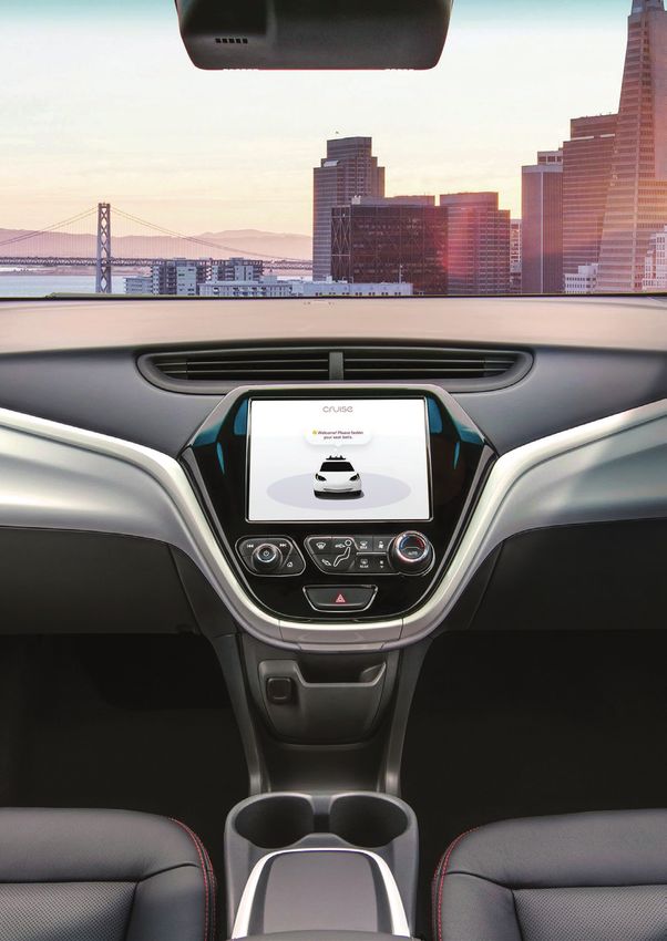
Smart
Autonomous
Mobility
Enable. Accelerate. Deploy.
Enabling customers of all types and
sizes to accelerate and deploy
a bold autonomous mobility vision.

mscsoftware.com/autonomous
Table of
                                                contents
Foreword                                  04

Leveraging VIRES VTD to Design a          05   Achieving Autonomous Driving with      25
Cooperative Driver Assistance System           Simulation & Testing
- Volkswagen Group                             - Dr. Luca Castignani

Leveraging Adams and Luciad to Assess     10   Generation and Validation of Sensor    29
Mobility Characteristics of a Military         Models for Automated Driving Systems
Ground Vehicle                                 Using VIRES VTD
- NATO                                         - BMW Group

Autonomous Vehicle Testing                14   Shaping Smarter Simulation             33
- Christopher Kinser, General Motors           with Artificial Intelligence
                                               - Dr. Horen Kuecuekyan

General Motors Advances Virtual           16   Road Testing or Simulation? – The      35
Autonomous Driving & Active Safety             Billion-Mile Question for Autonomous
- General Motors                               Driving Development
                                               - Dr. Luca Castignani

Multi-Resolution Traffic Simulation for   19   Author Profiles                        40
Connected Car Applications using
VIRES VTD
- AUDI AG
Foreword
                              The Autonomous Vehicle Industry has come a long way in the past
                              decade or so. Truly futuristic progress has taken place where
                              self-driving vehicles are concerned. A lot of resources and testing are
                              being spent on road testing which has been deemed as a very important
                              part of the process. However, road testing alone is simply not adequate
                              and not easible when it comes to ensuring the safety of humans and
                              vehicles on road. It would take us about a century to complete the
                              testing of one self-driving vehicle model if we only rely on physical
                              testing.

Every year, 1.24 million people die in traffic accidents and 50 million are injured worldwide
(WHO data, 2013), and over 90% of these collisions are due to human error. The deployment of Level 5
autonomous vehicles can potentially save hundreds of thousands of lives every year. Simulation has a
big role to play in accelerating the development of this sector. Industry leaders across the globe
including companies like General Motors, BMW, Audi, Volkswagen are leveraging virtual testing to
validate and to verify Advanced Driver Assistant Systems (ADAS) and autonomous driving systems.

This is where MSC Software wants to make a significant contribution through solutions like VTD where
we experiment every relevant driving condition, including system faults and errors. Companies like
Waymo is running a fleet of 25,000 virtual cars 24/7, simulating 13 million kilometers per day.
Simulation is critical to us for achieving billions of miles of testing for automated driving development.

With our e-book on autonomous driving, we hope the readers will gain valuable insights on recent
Research and Development in the self-driving space. The book also endeavors to shed some light on
why autonomous driving is important and what is realistically achievable in the next 5 to 10 years.

Dr. Luca Castignani
Head of Autonomous Mobility Strategy, MSC Software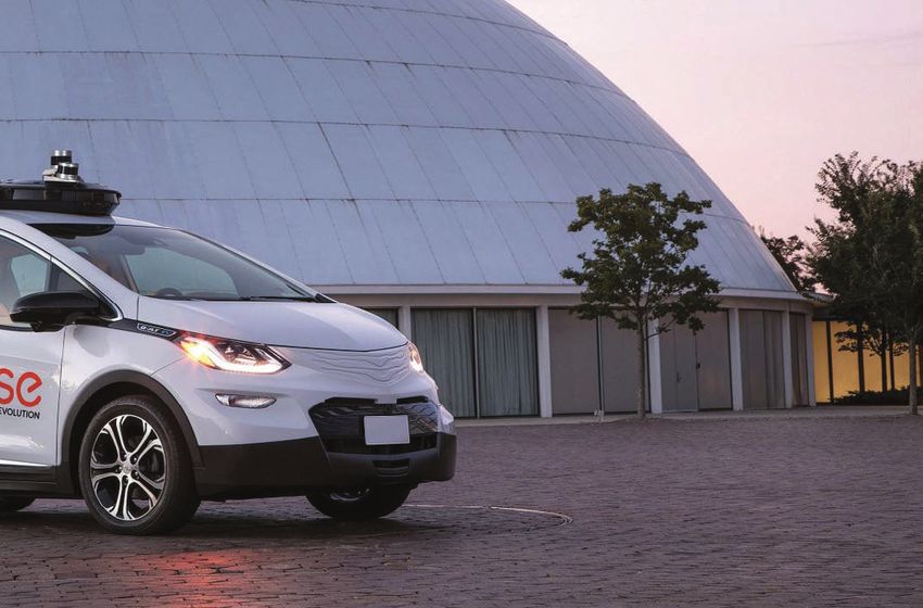
Volkswagen Group:
Leveraging VIRES VTD
to Design a Cooperative
Driver Assistance System
By Dr. Kai Franke, Development Online Driver
Assistance Systems, Volkswagen AG

                                               Virtual Test Drive | vires.com | 05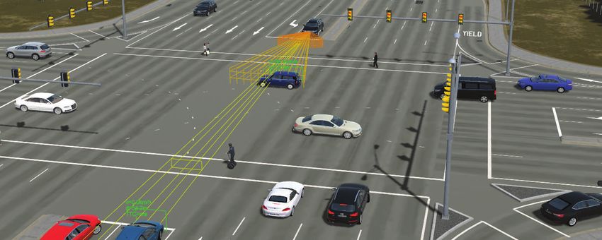
“A combination of ADTF, VTD,
                                                     and OMNet++ allows us to do a
                                                     host of experiments to test and
                                                          validate cooperative driver
                                                                assistance systems.”

                                                             the consideration of unequipped vehicle are some of
                                                             the key challenges for cooperative driving.

                                                             This article focuses on a test framework for CDAS,
                                                             which can be leveraged to master the complexity of
                                                             distributed driver assistance systems (DAS) during
                                                             the development process. A combination of ADTF
                                                             (the application prototyping framework within the
                                                             Volkswagen group), VTD (Figure 1, a simulation
                                                             tool-chain from VIRES GmbH) and OMNet++ (an
                                                             open-source component-based network simulator)
Figure 1. VIRES VTD is an open platform for developing       allows us to do a host of experiments to test and
Advanced Driver Assistance Systems                           validate cooperative driver assistance systems.

                                                             Simulation Framework

‘C
                                                             Since the development of CDAS requires at least two
            attention in recent years within automobiles.    interacting vehicles, the implementation and the
            In order to increase the quality of signals,
the availability and the perception range as well as to      framework for connected vehicles. Figure 2 gives an
decrease the latency and the probability of total failure,   overview of the proposed architecture used within
advanced perception systems consisting of camera,            this project (reference 1). The detailed description of
radar and lidar systems with vehicle-to-vehicle (V2V)        interfaces and functionality follows hereinafter.
communication are required. Moreover, V2V
communication enables advancements from individual           A. Application
to cooperative decision making. Advanced driver
assistant systems (ADAS), which determine their
                                                             planner implemented in ADTF (Automotive Data and
“cooperative behavior”, are capable of increasing the        Time triggered Framework) and a controller for each
total utility of a group of cooperative vehicles. However,   involved vehicle. There are three relevant interfaces
several technical issues have to be resolved on the way
                                                             environmental model and the current vehicle state
systems (CDAS) on our public streets. For example,           provided by the simulation gateway. The second
handling the misuse of the communication channel and         interface to the network enables the communication

                                                                                                   Virtual Test Drive | vires.com | 06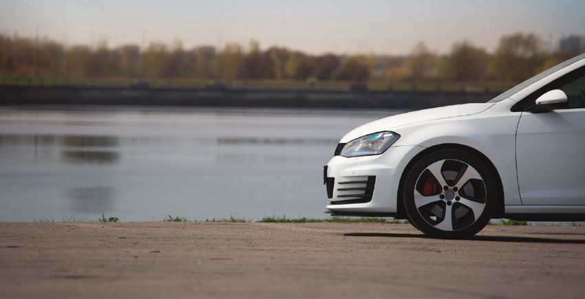
Figure 2. Overview of the VW simulation framework

between vehicles. The last interface to the simulation            The central component is the task control
gateway realizes the controllability of the vehicle.              coordinating additional modules with the help of the
                                                                  module manager. Additional modules are the
B. Simulation Gateway                                             scenario with roads and vehicle information, the

For each vehicle (here an example is shown for three              controlled vehicles and the Image Generator (IG).
                                                                  The virtual environment transmits its information via
among others two tasks: the modeling of the perception            Ethernet on the Real Time Data Bus (RDB)
(environment and vehicle state), and the reaction to              interface. Furthermore, the Simulation Control
controller outputs. The interface for the vehicle state           Protocol (SCP) interface provides a mechanism for
includes, but is not limited to, the velocity, the longitudinal   operating the simulation.
and lateral acceleration, and the steering wheel angle.
                                                                  D. Network
C. Virtual Environment
                                                                  The network simulation can emulate the
The software Virtual Test Drive (VTD) developed by                communication of the application via for example,
VIRES provides the virtual environment we used.                   ETSI ITS G5. In order to simulate the signal damping,
                                                                  the analog model uses information about line of sight
                                                                  and distances between the communicating vehicles.
                                                                  The RDB interface and the map of VTD (*.xodr
                                                                  format) contain the required information.

                                                                  Simulation Results

                                                                  A. Decentralized Decision Making

                                                                  An example of a merging scenario on a highway is
                                                                  chosen to demonstrate the usability of the decentralized
                                                                  decision making (see Figure 3). The red vehicle wants to
                                                                  merge onto the highway, while the two lanes are
Figure 3. Results of the planning methods for the merging
                                                                  blocked by a truck (yellow) and another vehicle (blue).
scenario of three vehicles                                        The lane width amounts to three meters each.

                                                                                                          Virtual Test Drive | vires.com | 07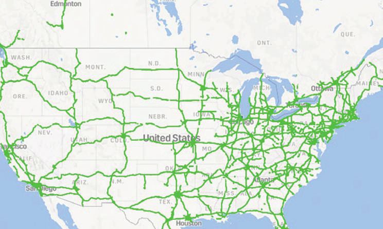
“The proposed
                                                                 simulation framework
                                                                      allows a flexible
Three different planning algorithms generate offers
                                                               modular combination of
for the merging scenario. It can be seen that the              software components.”
planning methods (a) and (b) recommend a lane
change for the truck, while method (c) makes the
truck stay in its lane. Planner (b) starts the lane
change later than planner (a). Planner (c) solves the

merging maneuver of the red vehicle behind the
truck. The diversity of the offers results from different
discretizations and different evaluation criteria. In
order to demonstrate the decentralized decision
making process, a cost function based on a fuzzy            of planner, controller, and vehicle dynamics. An
logic is applied, which enables a continuous                application for collision avoidance exemplarily
prioritization between comfort, driving enjoyment,          demonstrates the closed loop performance (Figure 4).

preferences of each vehicle. The truck focuses on           As an initial scenario, a driver starts an overtaking
                                                            maneuver on a rural road. The driver misjudges the
and the blue vehicle prioritizes comfort.                   situation and the danger of a collision with the

Each vehicle comes to a different evaluation or rating      detects the danger and starts/triggers the
of the offers, because of the varying preferences.          cooperative maneuver planning. The detection
The varying preferences can be caused by different          criterion could also be the time to collision (TTC). The
brands, different vehicle models (sedan, van or SUV),       TTC is calculated as the quotient of distance and
or by an online driver monitoring system. Table II          relative velocity. The calculated cooperative
shows the results of the evaluation of each plan by         maneuver plan targets the completion of the
each vehicle and the result of the two proposed             overtaking maneuver of the red vehicle and a
selection criteria. The selected solution (bold)            deceleration of the truck and the blue vehicle.
represents the compromise of the solution options.
Plan (c) is selected by the sum criterion and plan (a)
is selected by the squared sum criterion.                   longitudinal controller has a linear increasing controller
                                                            error. This is caused by a constant velocity error. A
B. Closed Loop Simulation                                   possible reason is that the longitudinal controller does

The closed loop or hardware-in-the-loop simulation          maneuver. In this case the vehicle decelerates
enables a study to evaluate the control error               stronger than planned. The lateral controller shows an
considering communication and calculation latencies         overshooting. The vehicle stays with 50 cm maximum

                                                                                                   Virtual Test Drive | vires.com | 08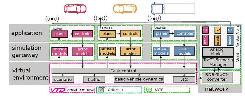
Figure 5. Results of closed loop simulation

controller error in a safe condition (stays on road, no   applications disable a development and later
collisions with obstacles). This error is caused by       validation without considering the multi-directional
latencies and systematic errors in the feed forward
controller. However, systematic errors, difference
between vehicle dynamics model and inverted model         components and considers modeling of perception,
in the feed forward controller, are made on purpose.      communication, and controlling of several vehicles in
A perfect vehicle dynamics model in the feed forward      a virtual environment.
controller is impossible in reality, because of for
example changing loads, changing wheel                    Reference
characteristics, and changing surface etc. Further
controller adaption will be done with the help of real    1. “A Cooperative Driver Assistance System:
                                                             Decentralization Process and Test Framework” by Kai

                                                             Jörn Günther, Proc. 7th Tagung
Conclusions                                                  Fahrerassistenzsysteme Conf., 2015.
                                                          2. Source: https://pdfs.semanticscholar.rg/6361/393b-
                                                             8c4067f857bf68f8ea7b79588eb19aba.pdf
A new CDAS (Cooperative Driver Assistance System)
imposes new requirements on simulation methods.
The high degree of connectivity and interaction of the

                                                                                                  Virtual Test Drive | vires.com | 09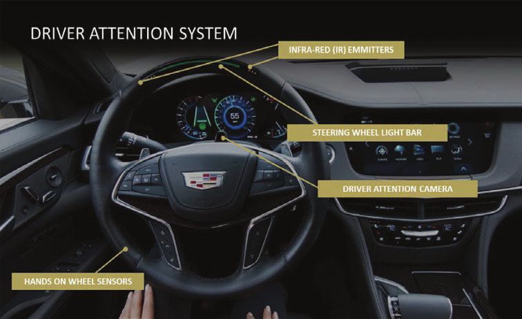
NATO: Leveraging
      Adams and Luciad
      to Assess Mobility
      Characteristics of a
      Military Ground Vehicle
      By Hemanth Kolera-Gokula,
      Product Marketing Manager, MSC Software

18 | Engineering Reality Magazine               Virtual Test Drive | vires.com | 10
Adams/Car Validated Model Complex Terramechanics • Drawbar
Parametric • Traverse
Vehicle Validation Simplified Terramechanics (with EDEM)
Model
Architecture
Rigid Road
• Drawbar
• Sand Climb
• Handling • Traverse
• Lane-change
Real-Time Model • Cornering
• Ride
• RMS roads
• Halfrounds
• Obstacles Uncertainty
Quatification
Virtual Test Drive
• Mapping
• Route Selection
(with Luciad)
Figure 1 Mobility modeling for the NG-NRMM program
T
he mobility of a ground vehicle can be the difference
between mission success and mission failure on the
battlefield. In today’s defense environment, there is a
need to create rapidly deployable, highly mobile vehicle
platforms that operate reliably across various terrain and road
types. Vehicle simulation capabilities for assessing performance
for different environmental conditions and operational scenarios
have increased significantly in recent years.
In support of the Next Generation NATO reference mobility
model (NG-NRMM) project for assessing existent CAE mobility
analysis capability different facets of the Hexagon product
portfolio were used to asses and visualize the mobility of the
Figure 2 FED-Alpha Vehicle Assemble in Adams
FED-Alpha, a Fuel Efficient Demonstrator vehicle (Figure 1).
Adams models was created and validated against real-world
calibration data by a team comprising of Eric Pesheck,
Venkatesan Jeganathan, Tony Bromwell, Aniruddh Matange
and Paspuleti Rahul Naidu to support this effort. These Alpha. Adams Car uses a template-based approach to model
validated models were then used to accurately predict vehicle building; Reusable parametric templates of sub-systems such as
performance under a variety of on- and off-road operational chassis, tires, powertrain etc. can be populated with vehicle data
scenarios. Select results from these investigations were and integrated to create a full vehicle assembly as shown in
integrated into Luciad, part of the Hexagon Geospatial Figure 2. Typical model data includes design hard points, part
portfolio, via a customized application for visualization and mass properties, and component compliance characteristics.
mobility mapping. Additionally, real-time compliance of the Adams Car allows detailed component representations, such as
Adams model to support various autonomous and “Hardware- flexibility, friction, or frequency-dependent behavior where
in-the-Loop” scenarios was demonstrated. warranted. The level of fidelity and detail employed in the model
was based on the simulation intent and available design data.
Creating and Validating the Adams Model
The accuracy of the model was validated by comparison
Adams Car, a solution vertical in the Adams portfolio focused on against data gathered from various vehicle test events. Metrics
the modeling and simulation of vehicle assemblies and sub- related to vehicle behavior, dynamics and ride quality were
systems was used to create a full-vehicle model of the FED- compared for model validation.
Virtual| Test
Volume IX - Summer 2019 Drive | vires.com| |19
mscsoftware.com 11Figure 3 Adams Model Validation against Test Data
Predicting Vehicle Performance Using the relationships, based on experimental measurements, to
Adams Model predict the response of deformable terrain to vehicle
operation. These methods are computationally efficient, and
The validated Adams model was then used to simulate various were used to assess vehicle performance for well-defined
vehicle events to evaluate vehicle performance and mobility. draw-bar and hill-climb analyses. In addition, these methods
These events consisted of both on and off road usage to mimic were applied to scanned terrain geometry for more
real battlefield scenarios. Typical military on-road evaluation generalized off-road performance analyses.
events such as double lane change, indicating limit handling
performance, half rounds, indicating ride quality, and step In addition, the computational efficiency of this method
climbs, indicating obstacle navigation ability, were stimulated, facilitated the support of stochastic analysis approaches,
with good agreement to test. where uncertainties due to variations in model and terrain
inputs were also accounted for, statistically. These stochastic
Evaluation of off-road performance is critical since simulations represented hundreds of potential soil
achievement of certain mission objectives could require characteristics, and allowed prediction of vehicle
operation over unprepared terrain. Of crucial importance in off performance over a statistical range of soil and terrain
road modeling are the representation of the terramechanics; properties and resultant development of confidence intervals
the soil properties and the interaction between the tire and for vehicle performance.
the soil surface. Simple and detailed models for the
description of the terramechanics were utilized in this Higher fidelity approaches, where the soil properties emerged
initiative. Simple terramechanics models use empirical from simulated particle interactions were also employed. This
was accomplished using a co-simulation between Adams and
EDEM, a Discrete Element Method (DEM) based simulation
offering from DEM solutions. In the DEM method, the material
WORKFLOW is represented by a collection of interacting particles with
simple shapes (typically based on circles and spheres). The
typical co-simulation workflow between Adams and EDEM is
as shown in Figure 3. Potential EDEM contact is defined for
designated vehicle parts. The displacement of these parts is
determined by Adams and provided to EDEM. EDEM then
1. Set-up EDEM simulation 2. Set-up Adams simulation determines the resultant reaction forces, which are passed
back to Adams.
Adams Using these approaches, tests such as a drawbar pulls, and
Co-Simulation
Interface sand-bed acceleration were simulated to gauge tractive
(ACSI)
3. Connect EDEM and behavior of the FED under various off-road scenarios. Though
4. Simulate! Adams via ACSI computationally intensive, these simulations were proved to
add significant fidelity and result in more accurate correlation
Figure 4 Adams EDEM Co-Simulation workflow to test results.
20 | Engineering Reality Magazine Virtual Test Drive | vires.com | 12Mobility Mapping in the loop (HIL) and ADAS applications, a reduced order,
real-time compliant variant of the full-fidelity model was
Leveraging the broader Hexagon portfolio (Figure 5), the Luciad created. The ability to derive vehicle dynamics modeling
Lightspeed technology from the Geospatial Business Unit was variants of varying fidelity, to support a specific simulation
used to project the FED Alpha mobility characteristics intent allows users to deploy a single modeling solution
predicted by Adams onto the test terrain at the Keewenaw without costly, error-prone model translations between
Research Center (KRC). The integration of Adams predictions various tools. Furthermore, with the Adams Real-Time
with geospatial mapping technology demonstrates the approach, the user has additional freedom to retain model
capability to visualize vehicle speed throughout a mapped features of interest. Typically, real-time vehicle performance
domain based upon a combination of soil, grade and predicted may be achieved with a few simplifications of select
vehicle performance data. Additionally, optimized routes can be component and connection representations, depending on
computed based on selected route endpoints. the analysis and integration requirements. In this case, only
the anti-roll bar model was simplified. The real-time model
Additional operational data such as side-slope predictions and was tested in the VTD (Virtual Test Drive) analysis environment
obstacle information can be incorporated into the above to demonstrate capability. In addition, the numerical accuracy
framework, thus creating a platform for comprehensive mobility and efficiency of this model was assessed relative to the
assessment on an actual terrain using simulated vehicle baseline full-vehicle performance.
performance data.
Adams has had a long standing presence in the area of
Real-Time Virtual Model Performance on-road analysis. This effort demonstrates how these models
can be extended using the broader Hexagon portfolio and
To demonstrate the applicability of the full fidelity Adams reused for off-road analysis in the context of road terrain
models used for mobility assessment, to adjacent Hardware representation, real time analysis and operational mapping.
INPUTS Learn more about Adams:
www.mscsoftware.com/adams
MAPPING, VISUALIZATION, ROUTE PLANNING ENVIRONMENT
Vehicle Capabilities
• Custom App in Lucy
Framework
• Custom Map Layers
• Generate Go/No-Go
Soil Data
• Custom Routing
Algorithm
Elevation
Figure 5 Mapping workflow, showing speed made good and route prediction
Virtual| Test
Volume IX - Summer 2019 Drive | vires.com| |21
mscsoftware.com 13Q&A
Autonomous
Vehicle Testing
With Christopher Kinser, General Motors,
Milford, Michigan, USA
E
ngineering Reality Magazine recently interviewed Chris Kinser from General
Motors, the Director of their Global Autonomous Driving Center in Michigan
and an industry expert in rapidly emerging sector of vehicles (AVs). He has
and his team in Milford is responsible for vehicle integration of several
General Motors’ advanced technology programs, including self-driving vehicles, as
well as automated driving and active safety technologies. Chris’s expertise in software,
controls systems and vehicle performance integration have been recognized with three
Boss Kettering Awards. Chris holds a Bachelor’s in Electrical Engineering from Kettering
University and a Master’s of Engineering from Rensselaer Polytechnic Institute, USA.
Volume X - Winter 2019 mscsoftware.com
Virtual| Test Drive | vires.com | | 9
14What does your role in General vehicles will be electric vehicles. Not
Motors involve and what is only are electric vehicles better for the
GM’s overall approach to the environment and quieter for city traffic,
fast-emerging Self-Driving but they allow for simpler integration
opportunity? of the advanced technologies required
for the cleanest and safest operation of
I am the Director of the Global autonomous vehicles. For example, an
Autonomous Driving Center at our Milford, all-electric vehicle has a more stable power
Michigan proving ground where I manage source and a faster responding propulsion
a large engineering team. We believe that system that provide it inherent advantages
autonomous technology will play a key role over its internal combustion counterparts.
in our vision of a world of zero crashes,
zero emissions and zero congestion
through the enormous potential benefits it Why did GM choose
holds for society in the form of increased Hexagon/MSC technology
safety and access to transportation. for its Autonomous Driving
strategy?
General Motors is in a unique leadership
position when it comes to developing and We see Hexagon as a company totally
deploying self-driving vehicles in that we devoted to the autonomous sector in its
are the only company to have everything business focus. Hexagon’s combination
from design, engineering, validation, and of sensor and scanning technologies
testing all under one roof. My team is works like Leica cameras, and its simulation
closely with teams all around the country on software suite like MSC’s VTD (Virtual
developing autonomous driving solutions. Test Drive) software, fill many of the
needs of the market. VTD is in the center
of a comprehensive GM simulation
What do you see as the big environment that we have developed with
challenges to Autonomous Hardware-in-the-Loop. We use VTD in
Mobility going mainstream in conjunction with software products like
the next 10 years? CarSim and Simulink (for control systems)
in our real time virtual automated driving
We are in the middle of a fundamental shift vehicle testing environment.
in how people and goods move through the
world. Autonomous mobility will certainly
play a huge part in that and at GM, we will What is your vision for GM
be guided by the needs of our customers. in the autonomous mobility
It is also one of the most difficult challenges space in say 5 years from
for automotive engineering. The biggest now?
challenge I see to Autonomous Mobility
going mainstream is getting all the systems It is still the early days of autonomous
necessary for self-driving vehicles to work mobility and we are excited by the
together seamlessly. Next time you’re opportunities for this technology to
behind the wheel, take a moment to reflect improve the world. In terms of engineering
on all the tasks you are performing to and development, we will continue to listen
drive the vehicle. Working on developing a to our customers and deliver advanced
system that can perform those same tasks mobility solutions that meet their needs.
is the engineering challenge of our lifetime.
That’s why at GM, we believe that a safe
self-driving vehicle should be built from the Which country or countries
ground up with seamless integration of the do you think will go fully
self-driving system. autonomous with cars first in
your opinion?
Will all autonomous cars be I can’t speak to the specifics of timing,
electric vehicles? but we have focused our shared
autonomous development on San
At GM, we believe that all autonomous Francisco and the United States.
10 | Engineering Reality Magazine Virtual Test Drive | vires.com | 15General Motors Advances
Virtual Autonomous
Driving & Active
Safety
By Chris Kinser, General Motors
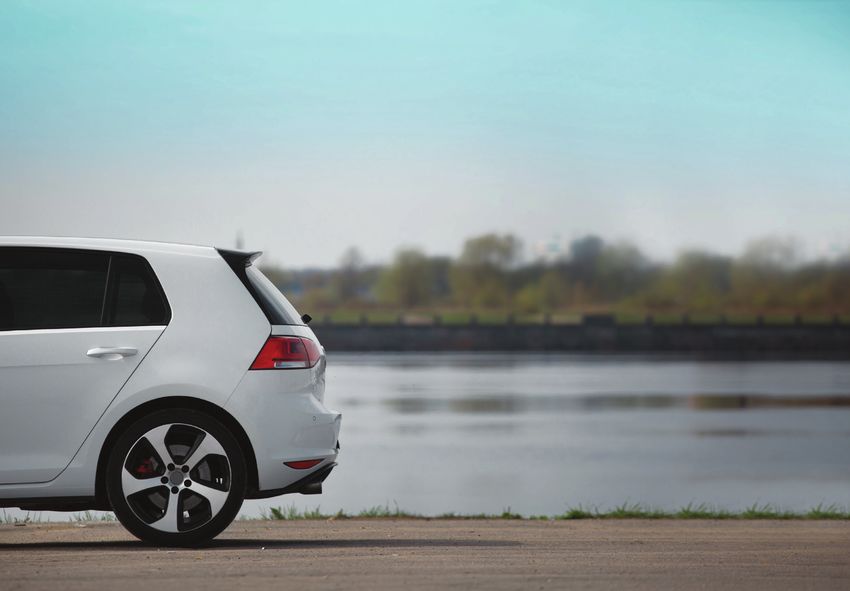
G
Figure 1: Cruise Autonomous Cars eneral Motors operates a total vehicle performance center at the Milford
Proving Ground in Michigan (Figure 2). The Global Autonomous Driving
Center is a subset of this work focused on developing active safety
features like advance park assist, lane keep assist, full-speed range
adaptive cruise, and Super Cruise. This work is guided by GM’s vision of
a future with zero crashes, zero emissions, and zero congestion. The mission of our team
is to provide smooth, capable driver assist systems that delight our customers.
GM’s Approach to Automated Driving
The industry standard scale for levels of autonomy (SAE) is helpful from an academic
perspective when discussing vehicles and their capabilities. However, when we begin
development of a new vehicle or system, we don’t start with a level in mind, but rather
with the use case and a set of features that we believe we can safely implement. It is this
focus on safety that guides us through the process.
General Motors is the only company that has everything from design, engineering
validation, and testing all under one roof. This is more than just designing and building
the vehicle. It also includes everything from in-house security and connectivity systems
to software development and high-resolution mapping. Having everything under one roof
puts us in a unique position to safely develop and deploy autonomous vehicle technology.
Super Cruise
Super Cruise is an advanced driver assistance feature that enables hands-free driving on
supported roads. It combines adaptive cruise control and lane-centering control with a driver
attention system (Figure 3) to allow you to drive with your hands off the wheel and eyes
on the road. Super Cruise is aimed at providing comfort and convenience in long-distance
travel and daily commutes. Customers receive updated maps on a regular basis (Figure 4).
Figure 2: General Motors operates a total
vehicle performance center at the Milford
Proving Ground in Michigan
Virtual
Volume X - Winter 2019 mscsoftware.com
| Test Drive | vires.com| |11
16Safety is
engineered
into every
step in Cruise’s
self-driving
vehicles Figure 3: General Motor’s Super Cruise
including design, Cadillac Driver Attention System
development,
manufacturing, Cruise Autonomous Vehicle
testing and (AV) Program
validation. In May 2016, GM completed the into every step in Cruise’s self-driving
acquisition of Cruise Automation a vehicles including design, development,
Silicon Valley startup with considerable manufacturing, testing and validation.
self-driving software development On a typical day, Cruise autonomous
expertise. Combined with our expertise in test vehicles safely execute 1,400 left
engineering and developing vehicles, our turns and our teams analyze all that data
teams began testing self-driving vehicles and apply learnings. Based on Cruise’s
in San Francisco, CA, Scottsdale, AZ experience of testing self-driving vehicles,
and Warren, MI. By September 2017, we every minute of testing in San Francisco
revealed our first self-driving test vehicle is about as valuable as an hour of testing
built from the start to operate on their in the suburbs because of the complex
own with no driver (1). Safety is engineered decisions being made.
Reference
‘How we built the first real self-driving car
(really)’, Kyle Vogt, Cruise, September 11, 2017
Blog Post: https://medium.com/cruise/how-
we-built-the-first-real-self-driving-car-really-
bd17b0dbda55
Figure 4: GM Super Cruise, before going to
production, required mapping every major
road in the U.S. and Canada
12 | Engineering Reality Magazine Virtual Test Drive | vires.com | 17Virtual Test Drive | vires.com | 18
AUT ONOMOUS

          Multi-Resolution
          Traffic Simulation
          for Connected Car Applications
          using VIRES VTD

          By AUDI AG: Andreas Kern
          Technical University of Munich: Manuel Schiller
          Institute of Transportation Systems: Daniel Krajzewicz
          VIRES, part of Hexagon: Marius Dupuis

                                                                   Virtual Test Drive | vires.com | 19
V
ehicular ad hoc networks available computing resources. This
(VANETs) have attracted a lot article presents an approach to solve this
of research attention over the trade-off by coupling multiple resolutions
last few years because they of traffic simulation to get highly accurate
have the potential to improve simulation results where they are needed,
traffic safety, efficiency and driver comfort. and simultaneously achieve an efficient
In fact, several ADAS (Advanced Driver simulation of large-scale scenarios of the
Assistance Systems) applications, such surrounding environment.
as cooperative driving and subsequently
automated driving, can only be achieved
through wireless communication between The Developed Multi-
the vehicles on the road. Resolution Traffic Simulation
Since those systems often exhibit safety- Microscopic Traffic Simulator: SUMO
critical features, rigorous testing and We chose to use Simulation of Urban
validation must be completed before their MObility (SUMO) as the traffic simulator
mass adoption. Although real road tests responsible for the simulation of the
using physical prototype vehicles offer the low-resolution area (LRA). SUMO is
highest degree of realism, the large amount a microscopic, space-continuous,
of resources needed to perform large-scale and time-discrete simulator. While it is
and extensive testing of vehicular networks employed in a wide range of research
renders their use impossible. Simulations domains, its most notable use is shown
are essential to validate the performance in a high number of research papers
of such solutions in large-scale virtual regarding VANET simulations. SUMO is
environments. Furthermore, simulation- well known for its high execution speed,
based evaluation techniques are invaluable as well as for its extensibility. SUMO is
for testing those complex systems in a wide ideally suited to simulate a high number
variety of dangerous and critical scenarios of vehicles residing in the LRA due to
without putting humans at risk. its efficiency, which is partly achieved
through its simplified driver model (which
In the automotive industry, the use of determines the path a vehicle will take).
simulation (Figure 1) is well established
in the development process of traditional Nanoscopic Traffic and Vehicle
driver assistance and active safety systems, Simulator: VIRES Virtual Test Drive
which primarily focus on the simulation of We employ the nanoscopic traffic and
individual vehicles with a very high level of vehicle simulator VIRES Virtual Test Drive
detail. When investigating and evaluating (VTD) for the simulation of the high-
the performance of ADAS based on resolution vehicles. VTD was developed
vehicular communication, this isolated
view of a single vehicle alone or a small
number of vehicles in the simulation is not
sufficient anymore. Potentially, every vehicle
equipped with wireless communication
technology could be coupled in a feedback
loop with the other road users participating
in the vehicular network, and therefore,
the number of influencers that need to be
considered is drastically increased.
These considerations lead to a trade-
off between accuracy in terms of the
simulation details for each vehicle and
scalability in terms of the number of
vehicles that can be simulated with the Figure 1: ADAS simulation
Virtual
Volume X - Winter 2019 mscsoftware.com
| Test Drive | vires.com| |69
20for the automotive industry as a virtual test been reached for SUMO and the condition
environment used for the development TVTD ≥ TVTD + SSUMO is therefore fulfilled, the
of ADAS and Autonomous Vehicles. Its state of the high-resolution vehicles is sent
focus lies on the interactive high-realism to SUMO through a gateway. This triggers
simulation of driver behaviour, vehicle the simulation of the next timestep in the
dynamics, and sensors. VTD is highly low-resolution model, and as a result, the
modular, so any standard component may positions of the low-resolution vehicles
be exchanged by a custom and potentially are passed back. These vehicles are now
more detailed implementation. Its standard classified, and, if applicable, the change
driver model is based on the intelligent of resolution is performed for individual
driver model; however, an external driver vehicles. When an exchange of a vehicle
model may be applied if necessary. The between the simulators happens, the
same concept applies to the vehicle previously mentioned inherent difference
dynamics simulation, where the standard in the underlying road network may cause
single-track model can be substituted by problems if a vehicle cannot be mapped
an arbitrarily complex vehicle dynamics based on its position in a specific lane due
model adapted for specific vehicles. Each to differences in accuracy. This is especially
simulated vehicle can be equipped with true for complex intersections which are
arbitrary simulated sensors, for example a modelled quite differently.
RADAR sensor, which is shown in Figure 2.
After all the resolution changes have been
Offline Pre-processing successfully completed, the simulation is
Figure 2: 3D visualization of a simulated
RADAR sensor in VIRES VTD To Enable Coupling unblocked again and the next timestep can
The two simulators rely on different data be simulated. This synchronization is very
formats representing the modelled road important to ensure reproducible simulation
network. In order to be able to run a results across multiple simulation runs.
co-simulation of both simulators, the
underlying data basis must match. VTD
uses the OpenDRIVE format to specify Dynamic Spatial Partitioning
the road network. This specification of The Simulated Area
models the road geometry as realistically
as possible by using analytical definitions. Our approach aims to couple traffic
SUMO on the other hand approximates the simulation models of different resolutions
road network geometry by line segments. at dynamic regions of interest. Contrary to
There are also differences in the modelling conventional traffic simulation, we are not
of intersections and lane geometries. interested in investigating a large number
To achieve a matching database, we of vehicles from a bird’s eye perspective,
convert the road network in an offline pre- but the focus is rather on a single vehicle
Figure 3: Dynamic partitioning of the processing step from OpenDRIVE to the (or a limited number of vehicles) which are
simulation area file format SUMO supports. used to conduct a test drive in the virtual
environment. This vehicle of interest has the
Online Coupling and Synchronization ADAS system under investigation onboard,
The coupling of the simulators at and is referred to as the EGO car. The
simulation runtime is based on the simulated measurements and sensor values
master-slave principle. Figure 4 shows are fed into the ADAS, and depending on its
this sequence of operations during a type and its use case, the respective ADAS
single simulation step, in which VTD and directly or indirectly influences the vehicle’s
SUMO can operate with different temporal state and behaviour.
resolutions without losing synchronization.
Based on this distance criterion, an area
SVTD is the length of a time step for the high- of interest is defined that centres around
resolution area (HRA), whereas SSUMO is the the EGO car, and in which the defined
length of a time step for the low-resolution simulative high-fidelity requirements
area (LRA). Typically, the nanoscopic must be fulfilled. Since the EGO car is
simulation is run at a higher frequency driving continuously through the virtual
than the microscopic one. TVTD and TSUMO environment, this area of interest is likewise
respectively denote the local simulation being moved along. We therefore partition
time in each simulator. At the beginning of the global area of the simulation dynamically
Figure 4: Comparison of simulation resolution each simulation step, a new timestep is into a high-resolution area (HRA) and a
switching simulated in VTD. If the next timestep has low-resolution area (LRA). Figure 3 shows
70 | Engineering Reality Magazine Virtual Test Drive | vires.com | 21a schematic view of the dynamic spatial
partitioning. There, the HRA is defined
as the area of a circle which is centred
around the EGO vehicle. Red vehicles
are within that circle and are therefore
simulated in high resolution by the involved
nanoscopic simulator, whereas the green
vehicles are outside of the circle and are VTD is highly modular, so any standard
consequently simulated in low resolution component may be exchanged by a
by a microscopic simulation. All vehicles
exist in the microscopic simulation, but in
custom and potentially more detailed
the nanoscopic simulation contains only implementation.
the high-resolution vehicles, and their
movements are applied to their proxy
counterparts in the microscopic simulator.
Due to the dynamic nature of road traffic,
the EGO car, the high-resolution vehicles
as well as the low-resolution vehicles
are permitted to move continuously. The
classification of the assigned resolution
mode is therefore performed after each
time step of the simulation. Vehicles the oncoming traffic flow. This artificial
for which the classification has led to a road was first modelled in the OpenDRIVE
change in resolution are transferred to format and was then converted to the
the appropriate simulator. This change of SUMO road network format.
resolution is possible in both directions at
every time step. However, since the HRA is We performed two series of experiments.
defined to be centred around the EGO car, In the first series, the nanoscopic traffic
it is always simulated in high resolution. simulator VTD was applied to the whole
simulated area. In the second series,
we used the described multi-resolution Figure 5: Hysteresis control of the simulation
In order to prevent vehicles which are close
resolution
to the boundary between HRA and LRA concept to partition the simulation area
from oscillating very frequently between between VTD and SUMO. We chose
the two resolution areas, a hysteresis a timestep of SVTD 20 ms for the high-
controller as depicted in Figure 5 is applied resolution area in VTD and a timestep of
in the classification process. As shown in SSUMO 1 s for the low-resolution area in the duration is around 12 ms, which is less
Figure 3, the two thresholds Rin and Rout SUMO. The hysteresis thresholds which than the timestep length of 20 ms and
are defined. A vehicle is transferred into define the dynamic area of interest were therefore yet fulfils the real-time constraint.
the high-resolution simulation only if its set to Rin 500 m and Rout 550 m. At around 150 vehicles, the duration
distance to the EGO car falls below the is beyond these 20 ms and real-time
value of Rin. The exchange back to the Performance Evaluation simulation is not possible anymore. With
low-resolution simulation is carried not out We measured the duration it takes to increasing vehicle count, the duration for
until the threshold Rout is exceeded. perform each simulation step over the each timestep also considerably increases
simulation period of 1,800 s, while the and reaches 180 ms at the end of the
number of vehicles was constantly being simulation period. This results in a factor
Simulation & Evaluation increased. Each series consists of five 15 computation time increase compared
separate simulation runs to account for to the amount of at the beginning of the
Scenario and Simulation Setup fluctuations in the measured execution simulation. The overall simulation took over
A synthetic scenario was created times. To illustrate the trends of the 120 min to complete, which is four times
for testing the coupling concept and measurements more clearly, the moving more than the simulated time.
evaluating its performance. It consists of average is also displayed in the following
a single straight road running west to east figures. Figure 7 shows the performance
with a length of 50 km and two lanes, one development of the multi-resolution
for each direction. Each lane is configured Figure 6 shows the performance simulation in the same simulation scenario
to have a constant inlet of 1,000 vehicles development of the nanoscopic simulation over the same simulation period. While the
per hour heading either east or west. The while increasing the simulated vehicle count total vehicle count is increased the same
EGO car is located near the start of the over the simulation period. The duration way as in the pure nanoscopic simulation,
road. It drives from west to east and is of each simulation step is almost constant the separately plotted nanoscopic vehicle
followed by a traffic flow, heading towards up to a count of 70 vehicles. Until then, count illustrates the number of cars
Virtual
Volume X - Winter 2019 mscsoftware.com
| Test Drive | vires.com| |71
22Figure 6: Simulation performance—nanoscopic simulation only Figure 7: Simulation performance: multi-resolution simulation
which are within the high-resolution area. on a dynamically-determined area of Reference
It shows that reducing the nanoscopic interest. The presented methodology
“Multi-resolution Traffic Simulation for Large-
model’s area of interest fulfils the aim of partitions the simulation area into a
Scale High-Fidelity Evaluation of VANET
reducing the overall simulation time. After variable, highly detailed region of interest Applications”, Manuel Schiller, Marius Dupuis,
a local maximum of 11 nanoscopic cars is represented by a nanoscopic model, Daniel Krajzewicz, Andreas Kern and Alois
reached, this count decreases slowly since with VIRES Virtual Test Drive (VTD), and Knoll, © 3rd SUMO Conference 2015 Berlin,
Germany
slower vehicles are left behind the faster the surrounding area simulated at low
moving EGO car. At around simulation resolution by a microscopic model. The
time 1,350 s, the two traffic flows from evaluation shows a dramatic reduction of
each end of the road meet in the middle computation time in comparison with a
of the road, which then increases the pure nanoscopic simulation of the same
nanoscopic vehicle count. However, simulation dimensions, which even makes
because the extent of the HRA is limited, real-time simulation possible. This divide-
the nanoscopic vehicle count does not and-conquer strategy enables accurate,
exceed a certain limit, which for the given realistic, and large-scale testing and
configuration is at around 27 vehicles. The validation of real implementations of driver
duration for the timesteps stays on average assistance systems based on vehicular
constant around 12 ms, so the overhead networks in a virtual environment. As
resulting from the coupling of the two the next step, we are investigating
simulators is negligible. The execution time the application of the multi-resolution
of the microscopic simulator is also shown simulation methodology for the other
to be negligible due to its less detailed, yet domains relevant for the simulation of
much more efficient, simulation model. The vehicular networks, namely network
overall simulation took less than 18 min simulation and application emulation,
to complete, so the simulation was faster to model the whole system across all
than real time by factor 1.66 and the real- domains efficiently at high fidelity.
time constraint was fulfilled throughout the
whole simulation period.
Conclusion
In this article, we proposed a concept
Open Standards Essential for Self Driving? Download our
for coupling traffic simulators of different
Free Whitepaper: www.mscsoftware.com/openstandards
simulation resolutions to achieve a multi-
resolution traffic simulation which focuses
72 | Engineering Reality Magazine Virtual Test Drive | vires.com | 23This divide-and-conquer
strategy enables accurate,
realistic, and large-scale
testing and validation of real
implementations of driver
assistance systems based on
vehicular networks in a
virtual environment.
Virtual Test Drive | vires.com | 24Achieving
Autonomous Driving
with Simulation & Testing
By Dr. Luca Castignani, Chief Autonomous
Driving Strategist, MSC Software
S
elf-driving is becoming more and more testing have we done so far? Waymo, the world’s
realistic. Every day, thousands of autonomous leading autonomous driving company in road testing,
vehicles (Figure 1) are being tested on the has accumulated an impressive 9 million miles in the
roads by companies like Waymo, Cruise, Uber, Tesla, past 9 years. However, even if we increase that effort
and some of those companies have accumulated by 10 fold, it would still take about 100 years for us
millions of miles of road testing data, enhancing and to complete the validation of one self-driving system,
validating their autonomous “brain”, with the hope that if we solely rely on road testing.
in the near future, full automation can be achieved.
As long as you only have to check a few use cases
When the Pumpkins Take a Stroll (in the range of tens), you can easily test them on
real roads. However, in order to assure safety for
Today, everyone understands the importance of road Autonomous Vehicles, the number of conditions to
testing for self-driving vehicles, and the industry is
spending a fortune on it. On an average, a fully
equipped autonomous vehicle can cost more than
half a million dollars, so a small fleet of 20 vehicles
would mean a 10-12 million dollars investment in the
hardware itself, to perform the road testing for
autonomous driving. However, is road testing really
enough to help us reach level 5 autonomy in the
foreseeable future?
To answer that question, first we need to
understand: how many miles of testing is required to
develop an autonomous driving system? The
commonly accepted number among the industry is
Figure 1. Autonomous Vehicle Testing Platform Developed
“one billion miles”. So how many miles of road by AutonomouStuff, Part of Hexagon
6 | Engineering Reality Magazine Virtual Test Drive | vires.com | 25materials (composites) analyses, CAE companies like
MSC Software (acquired by Hexagon AB in 2017)
have been providing industry leading simulation
attributes of every newly developed vehicle model.
Engineers have been using CAE to improve the
vehicle performance for a long time, so how is
autonomous driving simulation (Figure 3) different
than the traditional CAE simulation?
First of all, in an autonomous simulation environment,
Adams, Part of Hexagon
we need to capture more than the vehicle under
design (the so called “Ego Vehicle”). Different types
of participants need to be included in the scenario,
for example, other vehicles, pedestrians, cyclists,
be evaluated scales quickly to millions and there is animals (moose, deer, kangaroos) and so on.
no way to tackle it without simulations. For example:
What if you want to know how the car will behave Secondly, a realistic perception is crucial to
when the city decides to paint all the road signs in accurate simulation. Unlike the vehicle models in a
yellow instead of white? Or what happens when the traditional CAE environment, the “Ego Vehicle” in an
trees planted today grow to a size that prevents the autonomous testing model doesn’t always have a
driver from seeing the pedestrians? perfect understanding of its surroundings. Instead,
it only knows what its sensors perceive, therefore it
With simulation, it’s also possible to create outlier is important to accurately simulate those different
scenarios for testing. Think of workers carrying a types of sensors (cameras, RADAR, LiDARs…) and
large mirror while crossing the street. Think of also how they function especially in adverse
children dressed up as pumpkins, out for a walk on atmospheric conditions (sun glare, fog, snow, rain,
Halloween. Not many of these scenarios have been evening light…).
taken into consideration, but those are the realities.
These are just some examples that highlight how
How is Autonomous Driving Simulation autonomous driving simulation is very different than a
Different than the Traditional Vehicle traditional CAE car simulation, and for those same
Simulation? reasons, not every traditional CAE solution provider
Computer-aided engineering (CAE) simulation has simulation partner.
been a trusted tool leveraged by the automotive
industry for dozens of years now. From vehicle
handling & steering, ride & comfort (Figure 2), NVH,
durability, aerodynamics, controls validation, all the way Figure 3. Autonomous Driving Sensor Simulation Environment
to manufacturing process simulation and advanced by Vires VTD (Virtual Test Drive), Part of Hexagon
Virtual Test Drive | vires.com | 26Figure 4: Hexagon’s Complete Autonomous Driving Simulation & Testing Portfolio
A Comprehensive Strategy for (sensor fusion, object detection, path planning) or to
Autonomous Driving Simulation assess its performance in terms of safety, comfort
and Testing and efficiency.
Through a series of acquisitions with MSC Software B. Vehicle CAE Model
and VIRES VTD in 2017, AutonomouStuff in 2018,
along with indigenous domain expertise in sensors, Depending on the scenario that the simulation needs
smart city and positioning intelligence solutions, to address, having vehicle models with different level
Hexagon holds the leading edge in autonomous of complexity can be handy. For example, for a
driving validation (Figure 4). This includes solutions common scenario such as emergency braking on a
for these domains: Vehicle CAE Modeling, Sensor highway, a simplified model is preferred so a higher
Measurements and Modeling, 3D Environment number of scenario permutations can be verified in a
modeling, Scenario Testing, Data Management, AI given amount of time. For a more dynamic scenario
Driver and above all an open platform on which to that perhaps involves a swift lane change to avoid a
integrate these. crash, a higher fidelity Adams Car model with a
well-correlated suspension system is going to be
A. Virtual Test Drive (VTD) essential. Not to mention that within an autonomous
vehicle the riding comfort will become even more
VTD is an open platform for creation, configuration, critical to the passengers such as to not suffer
and animation of virtual environments for the testing motion sickness while reading your favorite book or
and validation of Autonomous Vehicles. It acts as the working with the laptop.
coordinator for the domain segments mentioned
above. It receives vehicle position and motions, C. Sensors and Sensor Models
rebuilds the 3D environment in real time (including
traffic and pedestrians), computes the sensor VTD has a complete set of sensors to replicate the
perception, calculates the movements of all physical sensors used in an autonomous vehicle:
surrounding vehicles and so on. This stream of data cameras (included infrared), LiDAR, RADAR and
can then be used to train the AI Driver at all levels ultrasonic sensor. Each sensor can be represented
8 | Engineering Reality Magazine Virtual Test Drive | vires.com | 27Figure 5. Creating Virtual 3D
Environment in VTD from Metrology
Road Measurements
F. Artificial Intelligence (AI) Driver
surfaces to simply capturing the basic sensor The AI Driver is the core of every autonomous system,
characteristics (in order to achieve the maximum and users can easily connect VTD to their own AI
Driver to carefully validate them under all conditions,
the variety of the sensor models, team VTD is also including sensor failure or misbehavior such as mud
working with the world-leading sensor manufacturers sputters covering a portion of a LiDAR. MSC Software
like Leica and NovAtel (all part of Hexagon). is also working with its sister company,
AutonomouStuff (both part of Hexagon), to connect
D. 3D Driving Environment AutonomouStuff’s AI Driver to VTD so partners of
AutonomouStuff can run their physical road tests and
A 3D virtual environment can be generated either virtual tests with exactly the same AI brain.
from inside VTD, or from scanning the actual roads.
Creating the environment inside VTD gives you In summary, today Hexagon owns many of the
maximum control over all the details, while simulation and testing assets necessary for
generating the 3D environment from measurements autonomous car projects: sensors and technology
(LiDAR/camera) is more realistic and much faster. to manage smart intermittent sampling, HD maps
With Hexagon’s new Leica Pegasus:2 mapping from Hexagon Geosystems, and a turnkey platform
platform and its connection with VTD (Figure 5), for autonomous vehicle development from
engineers are expected to speed up the “Road AutonomouStuff. Add in MSC Adams vehicle
Digitization” by a factor of 20 in the near future. modeling, VTD to recreate the external environment
E. Scenarios and Data Management SimManager, and there is a very compelling turnkey
autonomous vehicle solution toolset for both
With millions of scenarios to be evaluated at each simulation and testing awaiting both OEMs and
step of the autonomous vehicle development, there Start-ups around the world.
is simply no way to manage everything manually.
Indeed, Intel calculates that 1 Petabytes of data will
be generated each day by an autonomous vehicle.
That is where SimManager, the simulation
management platform of MSC, comes into play to
store the generated data and appropriately label
them for easy access at any stage. With such a
“needle in the haystack” (such as “extract all
simulations with rain”) is like child’s play and to
compute meaningful performance indexes (such as
“average time to collision”) becomes a no-brainer.
Virtual Test Drive | vires.com | 28BMW Group: Generation and
Validation of Sensor Models
for Automated Driving
Systems Using VIRES VTD
By Alexander Schaermann, Data Engineer, BMW Group
Timo Hanke, Data Engineer, BMW Group
Virtual Test Drive | vires.com | 29INTRODUCTION and true values, of the measurement and perception
performed by vehicle sensors.
D
ue to advancements in sensor technology and data
processing algorithms over recent years, great Sensor measurement models, on the other hand, are based on
progress has been made to enable automated driving a physical description of the measurement process, and they
systems to improve safety and comfort for the vehicle driver generate low-level measurement data based on the virtual
and occupants. Yet, due to the complexity of self-driving, one scene. Models of this type are commonly used for a variety of
of the main challenges remains in ensuring and validating the sensors in robotics research, while the measurement models
safe conduct of the automated driving systems for public use. for automotive sensors are only emerging.
Virtual worlds provide a suitable, safe and controlled In this article, we introduce a sensor measurement model for
environment to handle an important part of the required testing an automotive LiDAR sensor. The model is based on a ray
and validation efforts. A proper choice of scenarios as well as tracing approach for the simulation of the measurement
the generation of virtual sensor data that closely matches reality process. This enables the real-time generation of a LiDAR Point
are among the central requirements for the success of the virtual Cloud within the framework of an automotive driving simulator.
development approach. Virtual sensor data is generated by By directly comparing data from the real-world test drive to
means of sensor models that form a central component of the virtual data generated by the sensor model in a virtual
virtual environmental perception (Figure 1). This perception data environment, we are able to quantify the accuracy and validity
constitutes one of the main input streams for the decision of the sensor model using appropriate metrics.
making algorithms of an automated driving system. Hence, the
fidelity of the sensor model is a deciding factor for the viability SENSOR MEASUREMENT MODEL
and validity of virtual development and testing.
A. Real-time Ray Tracing in a Driving Simulator
Generally speaking, there are two types of sensor models:
We consider the scanning type of LiDAR sensor, which is
Sensor error models aim to reproduce the statistical typically used in the automotive industry. This type of sensor
characteristics of errors, i.e. deviations between the perceived determines distance by measuring the travel time of a laser pulse
reflected by a target surface. Its angular resolution is achieved by
means of scanning, i.e. by moving the transmitted laser beam as
well as the selective field of view of the optical detector array
successively over the sensor’s complete field of view. Most
commercially available systems at this time employ a
mechanically rotating mirror for the scanning task. The operating
principle of this type of sensor lends itself to a modeling
approach using ray tracing techniques. The virtual environment
for the proposed sensor model is provided by the Vires VTD
driving simulation software (Figure 2), which offers a ray tracing
framework based on the Nvidia OptiX ray tracing engine.
Figure 1. Virtual Sensor Models in VIRES VTD Environment
Experimental Vehicle Validation Simulation
Data Acquisition: Data Extraction: Simulation:
• Environment Model • Reference • Reference Scenario
• Reference .bag • Lidar Ref. • Sensor Models
• Lidar • OG
ROS Matlab Vires VTD
.mat
Validation: Environment Model:
• Metrics • OG
• Report .matÅ.bag
Matlab ROS
Figure 2. LiDAR Model Simulation in VIRES VTD Figure 3. Tool chain for sensor model validation
Virtual| Test
Volume IX - Summer 2019 Drive | vires.com| |15
mscsoftware.com 30You can also read