Numerical simulation of air flow in short metro ventilation shafts caused by a piston effect
←
→
Page content transcription
If your browser does not render page correctly, please read the page content below
MATEC Web of Conferences 305, 00050 (2020) https://doi.org/10.1051/matecconf/202030500050
SESAM 2019

 Numerical simulation of air flow in short metro
 ventilation shafts caused by a piston effect
 Nicolae Ilias 1 *, Omar Lanchava2, 3, and Giorgi Nozadze2
 1
 University of Petrosani, Department of mechanical engineering, 20 Universitaria, Petrosani,
 Romania
 2
 G. Tsulukidze Mining institute, Underground structures construction
 and mining technologies center, 7 Mindeli, Tbilisi, Georgia
 3
 Georgian Technical University, Department of occupational safety and emergency management, 77
 Kostava, Tbilisi, Georgia

 Abstract. Protecting the infrastructure of the metro from unauthorized
 actions with the help of ventilation openings of the systems is one of the
 main security problems of this type of transport. This article discusses the
 problem of the dynamics of distribution of the mass flow rate of ventilation
 air in a two-component system "tunnel - vertical ventilation shaft", due to
 the piston effect of a moving train. The dependence of the mass flow rate
 of ventilation air passing in both directions in short ventilation shafts (up to
 10 m), on the speed, location of the rolling stock and cross-sectional area
 of the ventilation shaft is investigated. It is shown, that at speeds of 10–20
 m / s of rolling stock and sections of the ventilation shaft of more than 4
 m2, the mass flow rate of air passing through the ventilation shaft must be
 taken into account with the mass flow rate of ventilation air in the transport
 tunnel for assessing the safety of the harmful aerosols. These processes can
 have a significant impact on the air quality of the underground
 infrastructure of the metro.

 1 Introduction
 Under the conditions of modern technological development, the most important task of the
 metro is to provide security measures in the context of growing environmental and terrorist
 threats. Through the vertical ventilation shafts, depending on the location of the trains, the
 effect of the piston caused by the movement of trains changes the direction of the air flow
 several times (at least 20 times per hour), which in certain cases can be considered as the
 possibility of distribution of uncontrolled air into the underground space. Therefore, there is
 the necessity to establish patterns of distribution air flows in the underground space using
 the methods of mathematical modeling. The modeling should be carried out taking into
 account the turbulence and inertia of the ventilation flow, as well as taking into account the
 different location of the train in the tunnels, the nature of its movement at different values
 of the cross section of the vertical shafts.
 ___________________________
 *
 Corresponding author: iliasnic@yahoo.com

© The Authors, published by EDP Sciences. This is an open access article distributed under the terms of the Creative Commons
Attribution License 4.0 (http://creativecommons.org/licenses/by/4.0/).
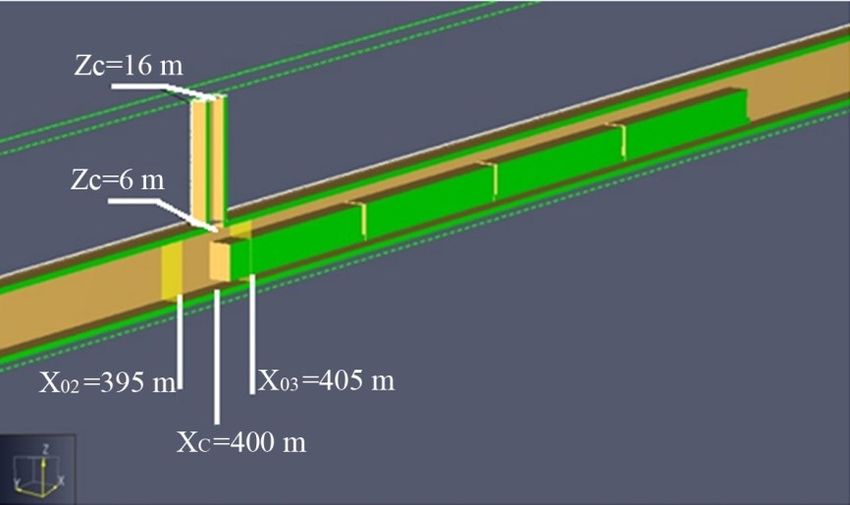
MATEC Web of Conferences 305, 00050 (2020) https://doi.org/10.1051/matecconf/202030500050
SESAM 2019

 As a rule, the aerodynamics of the piston effect is a complex multi-parameter problem.
 Consequently, the reliable determination of the aerodynamic resistance coefficient, which
 characterizes aerodynamics, meets with fundamental difficulties. To overcome the noted
 difficulties, in the present work it is assumed that similar processes take place in similar
 systems, and therefore using numerical and analytical methods, depending on the location
 of the train in the tunnel, the resistance coefficients are estimated, which can be interpreted
 as the first correlation. As it is known, the indicated coefficients are widely used in the
 traditional practice of aeromechanics.
 In modern scientific literature, many scientific papers have been devoted to the study
 the air flow caused by the piston effect of a moving train. In most works, the piston effect is
 considered as a positive factor in improving air exchange in the underground space. In work
 [1] the results of the study of air quality in underground structures of twenty countries of
 the world are considered.
 The issue of the spread of uncontrolled air flow through the ventilation shafts, as we
 know, was not considered in the works of other authors. In the papers [2-4] deals theoretical
 analysis of the piston effect and results of numerical modelling in subway tunnels. In the
 papers [5, 6] tables and graphs of changes in air flows generated by the piston effect are
 presented depending on the speed of the train and the degree of fill rate of the tunnel. In the
 paper [7] it is noted that the piston effect is characterized by two phases: non-stationary and
 stationary. The article also presents the method of mathematical modeling of the piston
 effect and illustrates the choice of the size of the simulation cells. The paper [8] focuses on
 the challenge of the air flow estimation by means of measurements and numeric analyses.
 In papers [9–11], the piston effect created by traffic has been considered and it is noted
 that this effect pushes air from the tunnel to the platform and the concentration of solid
 particles in the air increases as trains approach the platform. In work [12], problems of
 supplying fresh air to a metro station were considered, taking into account unorganized
 inflows caused by the influence of the piston effect, as well as temperature differences
 caused by the air conditioning. In the work [13], the effect of the piston is considered as an
 opportunity to save energy spent on airing the underground space.
 In the paper [14], as well as in [11] noted that particle generation in underground space
 occurs by mechanical wear at the brake–wheel and wheel–rail interfaces, where magnetic
 metallic flakes and splinters are released and undergo progressive atmospheric oxidation.

 2 Numerical Simulation Technique
 Below are presented the initial and boundary conditions for solving the task by means of
 the commercial software Pyrosim 2016:
 - Geometric parameters tunnel of metro are: length - 0 = 800 m; Area of cross section -
 0 = 20 m2; Perimeter - 0 = 18 m, Ventilation shaft is located in the central part of the
 transport tunnel, which is separated from the portal - = 0 /2; The shaft cross section
 is variable and takes values - = 1, 4, 9, 16 m2, and the vertical height of the shaft -
 ℎ = 10 m from the tunnel ceiling;
 - On the left portal of the tunnel there are the different meanings of excessive dynamic
 pressure ∆ = 10, 30, 50 Pa, while on the right portal are normal conditions - it means,
 that static pressure component does not change on the both portals;
 - The location of the train in the tunnel counted off from the left portal and takes value –
 = 202, 302, 351, 402, 502, 602 m. Train length - = 80 m, cross section of the

 train - St = 9 m2, tunnel fill factor - = ⁄ = 0.45;
 0
 - The solution of the proposed task is to define the air flow mass ratio in the tunnel
 characteristic cross sections, which location are in distance from the left portal - = 0,

 2
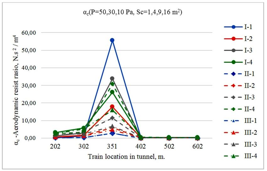
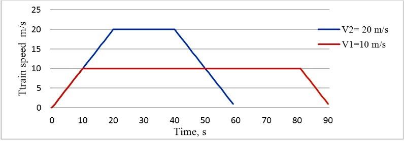
MATEC Web of Conferences 305, 00050 (2020) https://doi.org/10.1051/matecconf/202030500050
SESAM 2019

 395, 405, 800 m. Same time, the variable values of air mass exchanges for the central
 ventilation shaft in horizons are determined, with vertical distance = 6 m, 16 m from
 the tunnel bottom. The realization of the initial and boundary conditions of the task in
 the software is presented in Figures 1-2.

 Fig. 1. (A) Boundary conditions at the left portal of transport tunnel are: ΔP=10, 30, 50 Pa
 (B) Boundary condition at the right portal of transport tunnel are normal and Finite volume cell
 dimentions are 0.5 x 0.5 x 0.5 m

 Fig. 2. Air mass rate detectors location in tunnel near of ventilation shaft: 395 m, 400 m, 405 m from
 left portal and 6, 16 m from the bottom of tunnel

 The train movement velocity diagram is represented on the Fig. 3 for the two operating
 speed from the practice of Tbilisi metro exploitation. They are: V1 = 10 m/s, V2 = 20 m/s.

 3
MATEC Web of Conferences 305, 00050 (2020) https://doi.org/10.1051/matecconf/202030500050
SESAM 2019

 Fig. 3. Standard diagrams of train movement in the subway transport tunnel

 3 Results and discussion
 The results of modeling the reverse problem are presented as graphs on the Fig 4.

 Fig. 4. Dependence of air mass rate in the ventilation shaft based on the location of the rolling stock
 in the transport tunnel for the boundary conditions: I- 50 Pa, II-30 Pa, III -10 Pa and the shaft cross
 section areas: 1 - =1 m2; 2 - = 4 m2; 3 - = 9 m2; 4 - =16 m2

 The reversibility of the problem lies in the fact that the stream of air of varying
 intensity moves through tunnel and blows a stationary train. Consequently, the tunnel in
 these tasks is similar to the aerodynamic tube, in which studies are carried out on fixed
 models of transport.
 For the practical use of received results of numerical modeling by means of Basic Law
 of parallel networks have been calculated values of aerodynamic resistance coefficients (α)
 for investigated tunnels (vertical ventilation shaft and tunnel without and with train) by

 4
MATEC Web of Conferences 305, 00050 (2020) https://doi.org/10.1051/matecconf/202030500050
SESAM 2019

 results of modeling. Consequently, in presented paper have been calculated mass rate of air
 flows investigated by numerical modeling for the listed sites. Basic Law air flows in the
 parallel networks for our task will be takes followed form

 0 02 = 1 12 = 2 (1)

 Where 0 , 1 , is aerodynamic resistance of the listed sites of tunnel, N.s2/m8;
 0 , 1 , - mass part of the airflow, calculated in the cross sections of the listed sites, kg/s.
 Considering that

 0 02 ΔPk 0 02 ∆ ∝
 Δ = R 0 Q20 , 1 = = , = = and = (2)
 12 12 2 2 3

 Where ∝ - is the aerodynamic resist ratio of the ith section of the tunnel, N.s 2/m4; L i - the
 length of the ith section of the tunnel, m; Pi - the perimeter of the ith section of the tunnel, m;
 Si - the area of the ith section of the tunnel, m2.

 For the calculation of the aerodynamic resist ratio of the mentioned sections of tunnel
 were used formulas

 2∆ 03 3 3
 ∝0 =
 12 0 0
 , ∝1 = ∆ 2 1 11, ∝ = ∆ 2 (3)
 1 1

 Where ∝0 is aerodynamic resist ratio of tunnel part without train, N.s2/m4; ∝ 1 -
 aerodynamic resist ratio of tunnel part with train, N.s2/m4 and ∝ – aerodynamic resist ratio
 of ventilation shaft, N.s2/m4. For the calculation by formulas (3) there are an additional
 initial dates - = (1- 0 ) = 11 m2, = 80 m, = 0 + 1 = 20+12 = 32 m2, = 1, 4,
 9, 16 m2, = 4, 8, 12, 16 m, = 10 m.

 Below on the Fig. 5 are presented graphs of numerical calculation of aerodynamic
 resist ratio.
 Taking into account the nonstationarity of the piston effect, by the phases of
 acceleration and decceleration of the moving trains in the first correlation can be considered
 the duration of the non-stationary phase of the movement of the air flow. Depending on the
 results of the numerical modeling on the speed of movement in the subway transport tunnel
 (see Figure 3), it is possible to determine the duration of the process of suction of
 atmospheric air into the transport tunnel through the ventilation shaft
 0 −
 = − (4)
 2

 Formula (4) also provides for the fact that there is no practical process of suction
 atmospheric air into the transport tunnel through the ventilation shaft when the train closes
 perimeter of shafts and because of this, the drag coefficient seems to take values close to
 infinity. The duration of aerodynamic processes, depending on the presented two working
 speeds (V1 = 10 m / s, V2 = 20 m/s) and acceleration = 1.0 m/s2, calculated by the
 formula (4), gives the following time interval of 26 s <
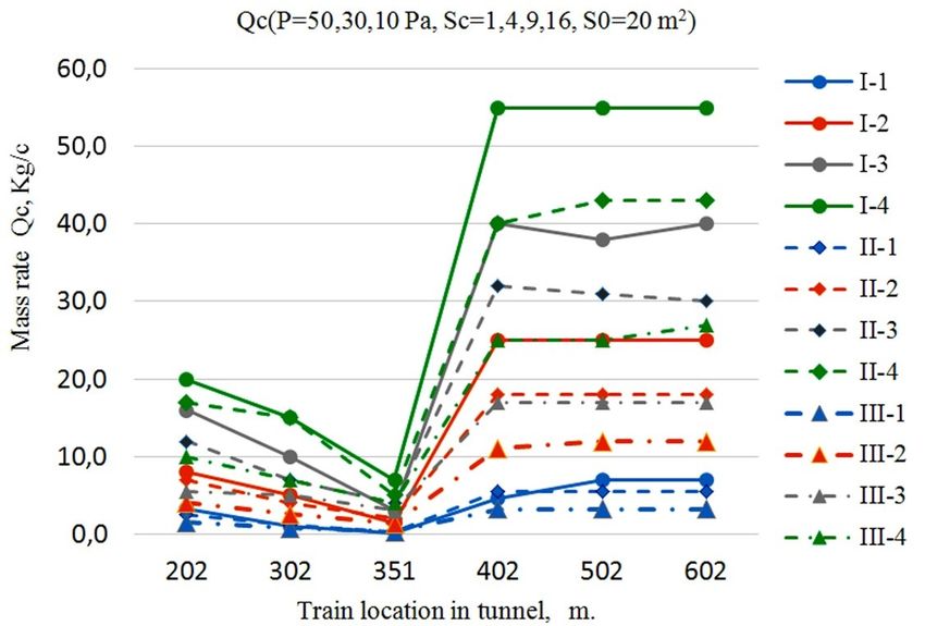
MATEC Web of Conferences 305, 00050 (2020) https://doi.org/10.1051/matecconf/202030500050
SESAM 2019

 Fig. 5. Dependence of αc – aerodynamic resist ratio in the ventilation shaft based on the location of
 the rolling stock in the transport tunnel for the boundary conditions: I- 50 Pa, II-30 Pa, III -10 Pa and
 the shaft cross section areas: 1 - = 1 m2; 2 - = 4 m2; 3 - = 9 m2; 4 - =16 m2

 The software for Numeric modeling use the finite volume method, where discrete
 volume units 0.5x0.5x0.5 m was selected by the recommendations of the Programmers,
 developed this software.
 Validation of numerical modeling in the research process has been checked by the
 storage law of mass rate for the parallel networks. In the given task, mass rate detektors
 were located in the cross sections corresponding to coordinates X = 395 m, X = 405, (X =
 400 m, Z = 6 m).

 =395 = =400 + =405 (5)

 Maximum relative error in the study process was 12.1%.

 Q 395−(Q400 +Q 405)
 ∆ = ∗ 100% = 12,1% (6)
 Q395

 Based on numerical modeling of the presented task, we can determine the minimum
 depression and the amount of the volume of suction of atmospheric air depending on the
 length of the metro tunnel and the location of the train. In the presented task there are
 evidence to neutralize the flow caused by the piston effect of moving train.
 The mass of the of suction of atmospheric air by the piston effect caused by the train
 movement in the transport tunnel can be calculated using the formula

 = (7)
 2

 6
MATEC Web of Conferences 305, 00050 (2020) https://doi.org/10.1051/matecconf/202030500050
SESAM 2019

 4 Conclusions
 As part of the proposed work, the validation of numerical method was carried out using the
 example of the law of conservation of air mass for parallel networks. The accuracy of the
 results is approximately 12.1%.
 Based on numerical modeling, it was established that due to the influence of the piston
 effect, an uncontrolled mass of air can flow into the underground space, the flow rate of
 which depends on the velocity and location of the train in the tunnel, as well as on the cross
 section area of the shaft. According to the last indicator, the marked consumption has a
 clearly defined minimum and its effect on the aerodynamics of the underground space
 should be taken into account if the shaft cross section area is more than 4 m2.
 Aerodynamic resistance coefficient for the vertical shaft as well as for the parts of
 tunnel with and without train can be determined by geometric data of the ventilation shaft
 and the location of the moving train in the transport tunnel taking into account the presented
 results.

 References
 1. B. Xu, J. Hao, Environment International 107, 33–46 (2017)
 2. O. Lanchava, N. Ilias, G. Nozadze, S. Radu, R. Moraru, Z. Khokerashvili, N. Arudashvili,
 Environmental Engineering and Management Journal 18(4), 865-872 (2019)
 3. O. Lanchava, G. Nozadze, Bulletin of the Georgian National Academy of Sciences 13(1), 38-44
 (2019)
 4. O. Lanchava, G. Nozadze, Proceedings of the The 10th International Multidisciplinary
 Symposium "Engineering Computational Technology 2018 - ECT 2018" (2018)
 5. O. Lanchava, G. Nozadze, Z. Khokerashvili, N. Arudashvili, Mining Journal 2(39), 37-45
 (2017, Tbilisi, in Georgian)
 6. O. Lanchava, N. Ilias, G. Nozadze, S. Radu, R. Moraru, Z. Khokerashvili, N. Arudashvili,
 Proceedings of 8th International Symposium “Occupational Health and Safety” SESAM 2017,
 342-352 (2017)
 7. O. Lanchava, G. Nozadze, Z. Khokerashvili, Proceedings of 9th International Conference
 “Contemporary problems of architecture and construction”, 390-392 (2017)
 8. C. Di Perna, A. Carbonari, R. Ansuini, M. Casals, Tunnelling and Underground Space
 Technology 42, 25–39 (2014)
 9. J. Wang, L. Zhao, D. Zhu, H.O. Gao, Y. Xie, H. Li, X. Xu, H. Wang, Transportation Research
 Part D47, 77–88 (2016)
 10. L. Mendes, M.I. Gini, G. Biskos, I. Colbeck, K. Eleftheriadis, Environmental Pollution 239, 82-
 94 (2018)
 11. T. Moreno, V. Martins, X. Querol, T. Jones, K. BéruBé, M.C. Minguillón, F. Amato, M.
 Capdevila, E. de Miguel, S. Centelles, W. Gibbons, Science of the Total Environment 505,
 367–375 (2015)
 12. Y. Zhang, X. Li, Journal of Wind Engineering & Industrial Aerodynamics 175, 384–390 (2018)
 13. L. Yang, Y, Zhang, J. Xia, Sustainable Cities and Society 37, 275–287 (2018)
 14. Z. Yang, X. Su, F. Ma, L. Yu, H. Wang, J. Wind Eng. Ind. Aerodyn. 147, 120–131 (2015)

 7
You can also read