ONE-STEP MICROWAVE-ASSISTED SYNTHESIS AND VISIBLE-LIGHT PHOTOCATALYTIC ACTIVITY ENHANCEMENT OF BIOBR/RGO NANOCOMPOSITES FOR DEGRADATION OF ...
←
→
Page content transcription
If your browser does not render page correctly, please read the page content below
materials
Article
One-Step Microwave-Assisted Synthesis and Visible-Light
Photocatalytic Activity Enhancement of BiOBr/RGO
Nanocomposites for Degradation of Methylene Blue
Kun-Yauh Shih *, Yen-Ling Kuan and En-Rui Wang

                                          Department of Applied Chemistry, National Pingtung University, Pingtung 90003, Taiwan;
                                          axw13671035@gmail.com (Y.-L.K.); transformersprime12345678@gmail.com (E.-R.W.)
                                          * Correspondence: sky@mail.nptu.edu.tw

                                          Abstract: In this study, bismuth oxybromide/reduced graphene oxide (BiOBr/RGO), i.e. BiOBr-G
                                          nanocomposites, were synthesized using a one-step microwave-assisted method. The structure of
                                          the synthesized nanocomposites was characterized using Raman spectroscopy, X-ray diffractometry
                                          (XRD), photoluminescence (PL) emission spectroscopy, scanning electron microscopy (SEM), trans-
                                          mission electron microscopy (TEM), Fourier-transform infrared spectroscopy (FTIR), and ultraviolet-
                                          visible diffuse reflection spectroscopy (DRS). In addition, the ability of the nanocomposite to degrade
                                          methylene blue (MB) under visible light irradiation was investigated. The synthesized nanocom-
                                          posite achieved an MB degradation rate of above 96% within 75 min of continuous visible light
                                irradiation. In addition, the synthesized BiOBr-G nanocomposite exhibited significantly enhanced

                                          photocatalytic activity for the degradation of MB. Furthermore, the results revealed that the separa-
Citation: Shih, K.-Y.; Kuan, Y.-L.;
                                          tion of the photogenerated electron–hole pairs in the BiOBr-G nanocomposite enhanced the ability
Wang, E.-R. One-Step
                                          of the nanocomposite to absorb visible light, thus improving the photocatalytic properties of the
Microwave-Assisted Synthesis and
                                          nanocomposites. Lastly, the MB photo-degradation mechanism of BiOBr-G was investigated, and the
Visible-Light Photocatalytic Activity
Enhancement of BiOBr/RGO
                                          results revealed that the BiOBr-G nanocomposites exhibited good photocatalytic activity.
Nanocomposites for Degradation of
Methylene Blue. Materials 2021, 14,       Keywords: photocatalytic activity; bismuth oxybromide; graphene; microwave-assisted synthe-
4577. https://doi.org/10.3390/            sis; nanocomposites
ma14164577

Academic Editors: Andrea Petrella
and Alina Pruna                           1. Introduction
                                                Since 1972, the principle and applications of photocatalysis have been extensively
Received: 8 July 2021
                                          investigated. Recently, with the increase in environmental protection awareness, photo-
Accepted: 11 August 2021
                                          catalysis has attracted significant attention for the treatment of environmental pollution
Published: 15 August 2021
                                          and the conversion of solar energy [1–3]. As an advanced oxidation process, photocatalysis
                                          generates electron–hole pairs via light irradiation of photocatalysts. This photocatalytic
Publisher’s Note: MDPI stays neutral
                                          degradation reaction can be attributed to the excitation of electron radiation in the va-
with regard to jurisdictional claims in
                                          lence band (VB) to the conduction band (CB) and the formation of holes with positive
published maps and institutional affil-
iations.
                                          charges in the VB. During photocatalysis, the adsorbed material further reacts with the
                                          electron and hole to produce numerous oxidized substances that can degrade some organic
                                          pollutants [4,5].
                                                Titanium dioxide (TiO2 ) is a traditional photocatalyst with high photocatalytic ac-
                                          tivities and low toxicity [6,7]. Currently, TiO2 is the most commonly used photocatalytic
Copyright: © 2021 by the authors.
                                          material owing to its low toxicity, which significantly limits its negative impact on the
Licensee MDPI, Basel, Switzerland.
                                          environment [8]. However, the large band gap of TiO2 (3.2 eV) limits its ability to effec-
This article is an open access article
                                          tively convert solar energy. This is because it can only be excited by ultraviolet (UV) light
distributed under the terms and
                                          (λ < 390 nm), which makes up only approximately 7% of the solar spectrum [9]. To increase
conditions of the Creative Commons
Attribution (CC BY) license (https://
                                          the effective utilization of solar energy, researchers have devoted tremendous efforts to de-
creativecommons.org/licenses/by/
                                          veloping a new photocatalyst that can perform photocatalysis in the visible light range and
4.0/).                                    clean the environment in an effective and environmentally friendly manner [10]. Bismuth

Materials 2021, 14, 4577. https://doi.org/10.3390/ma14164577                                             https://www.mdpi.com/journal/materials
Materials 2021, 14, 4577                                                                                           2 of 14

                           oxyhalides (BiOX, X = Cl, Br, and I) have attracted increased attention for the visible light
                           photocatalytic degradation of organic pollutants [11,12]. Liu et al. [13] combined BiOI with
                           BiOCl or BiOBr to prepare BiOI/BiOCl, which exhibited a methyl orange (MO) removal
                           of 78% after 150 min visible light irradiation. In addition, Meng et al. [14] utilized Pd
                           surface-modified BiOBr nanoparticles to degrade phenol and found that the nanoparticles
                           exhibited a 100% phenol removal after 300 min visible light irradiation. However, the re-
                           combination of the photogenerated electrons and holes of BiOX reduces the photocatalytic
                           activity of the catalyst [15]. The high electron and hole recombination rates of BiOX have
                           restricted its further application. [16,17].
                                Graphene is a well-known special material globally [18]. The lifetime of the electron–
                           hole pairs of a photocatalyst can be enhanced by adding graphene materials to the pho-
                           tocatalyst. This is because the high conductivity of graphene reduces charge recombi-
                           nation [19]. Consequently, graphene-based photocatalysts have attracted tremendous
                           attention owing to their photocatalytic efficiency. For example, Liang et al. [20] synthesized
                           NiFe2 O4 -reduced graphene oxide (RGO) nanocomposites and found that these materials
                           exhibited 99.1% methylene blue (MB) removal under 180 min UV irradiation. In addition,
                           Liu et al. [21] prepared an RGO-wrapped TiO2 hybrid and found that the catalyst exhibited
                           100% MB removal under 150 min UV irradiation. Furthermore, Patil et al. [22] synthesized
                           BiVO4 /Ag/rGO hybrid architectures and found that the catalyst exhibited approximately
                           90% MB dye removal.
                                Several methods, such as ultrasonication, hydrothermal method, solvent heat method,
                           and the sol-gel method, are used for the synthesis of photocatalysts. In a previous study,
                           an H3 PW12 O40 /TiO2 composite photocatalyst was prepared using a high-intensity ul-
                           trasonication method at a low temperature (80 ◦ C). The H3 PW12 O40 /TiO2 photocata-
                           lyst exhibited a 95% MB degradation rate under 90 min solar irradiation [23]. In addi-
                           tion, Vadivel et al. [24] synthesized an Sm-BiOBr/rGO composite photocatalyst using a
                           solvothermal method by utilizing methanol as the solvent. The synthesized photocatalyst
                           exhibited promising potential for the degradation of various hazardous chemicals and or-
                           ganic pollutants. Behera et al. [25] synthesized a series of ZnFe2 O4 @RGO nanocomposites
                           using hydrothermal and calcination methods and investigated their applications for the
                           degradation of ciprofloxacin. Farhadian et al. [26] synthesized N, S-doped TiO2 (NST), N,
                           S-doped ZnO (NSZ), and their composites with chitosan (NST/CS, NSZ/CS) using the
                           sol gel-hydrothermal method. They found that NST/CS exhibited the highest tetracycline
                           degradation efficiency of 91% under 20 min visible light exposure. Chamjangali et al. [27]
                           prepared nanoflower-like Ag-ZnO photocatalysts using a photoreduction and solution
                           precipitation method and investigated their application for the photocatalytic degradation
                           of MO and MB. Kumar et al. [28] synthesized Ag/TiO2 by dispersing Ag nanoparticles
                           into ethanol under sonication, after which TiO2 was added to the ethanol solution. The
                           synthesized catalyst exhibited the photocatalytic degradation of MB under UV-C light irra-
                           diation. Liang et al. [29] synthesized magnetic Fe3 O4 @BiOI@AgI spheres using a multi-step
                           process. The synthesized spheres exhibited excellent visible light driving activity against
                           RhB, BPA, and E. coli cells. Sanaa et al. [30] synthesized yBiOBr-(1−y)BHO heterojunction
                           using hydrothermal synthesis and solution mixing methods, and the heterojunction exhib-
                           ited enhanced visible-light photocatalytic properties. Some researchers have synthesized
                           nanocomposites by combining BiOBr and graphene and investigated their potential for the
                           degradation of organic pollutants in wastewater. Jiang et al. [31] synthesized BiOBr-RGO
                           nanocomposites using the hydrothermal method, and they found that the nanocomposites
                           exhibited 100% nitrobenzene degradation after 360 min visible light irradiation. These
                           studies indicate that the introduction of RGO to BiOBr could enhance its visible-light pho-
                           tocatalytic activity. Janani et al. [32] synthesized a magnetic RGO–BiOBr (MRGO–BiOBr)
                           composite by subjecting MRGO and BiOBr to ultrasonication separately for 30 min, after
                           which they were mixed together under magnetic stirring for 24 h. The effects of parameters,
                           such as catalytic dose and initial dye concentration, were investigated under visible light
Materials 2021, 14, 4577 3 of 14
irradiation. The results revealed that the composite exhibited 76.24% MB dye removal after
120 min visible light irradiation.
However, the large energy consumption and long reaction time of these methods have
limited their further application. To overcome these challenges, in this study, we employed
a simple, efficient, time-saving, and environmentally friendly, one-step synthesis method
for the synthesis of photocatalyst nanocomposites. The fabrication of nanomaterials using
microwaves is an environmentally friendly and cost-effective method. In addition, the
microwave-assisted method can obtain high-purity products, improve product yields,
and increase reproducibility [33]. In this study, BiOBr, a photocatalyst with visible light
photocatalytic ability, was selected and combined with RGO to synthesize a BiOBr/RGO
(BiOBr-G) photocatalyst. Furthermore, the microwave-assisted method was employed
to synthesize BiOBr-G within short durations, and the photocatalytic activity of these
nanomaterials was investigated. In addition, the crystal structure, morphology, functional
groups, absorption spectra, and photocatalytic mechanism were investigated using various
methods. The photocatalytic activity of the nanocomposites was investigated by evalu-
ating their MB degradation ability. BiOBr and BiOBr-G photocatalysts were successfully
synthesized, and their pollutant degradation abilities were investigated. Lastly, their effects
on electron–hole pair separation were also discussed.
2. Materials and Methods
2.1. The Materials Used
Bismuth nitrate Bi(NO3 )3 ·5H2 O was obtained from Sigma-Aldrich (St. Louis, MO,
USA). Potassium bromide (KBr) and natural graphite powder (99.99%, metals basis) were
purchased from Alfa Aesar (Haverhill, MA, USA). All of the chemicals used in the study
were of analytical grade. The aqueous solutions were prepared using deionized (DI) water.
2.2. Preparation of Graphene Oxide
In this study, GO was synthesized from graphite powder using the modified Hummers
method [34]. Briefly, 70 mL of concentrated sulfuric acid (Japan Chemicsl Industries Co.
Ltd, Shimizu-ku, Japan ) was placed in an ice bath and cooled to 5 ◦ C. Subsequently,
graphite powder, NaNO3 , and KMnO4 were added into the flask and stirred evenly for 2 h.
Thereafter, 300 mL of DI water and 10 mL of 30% hydrogen peroxide were added to the
solution to stop the reaction. Subsequently, the solution was subjected to suction filtration,
after which the product was placed in 500 mL of 5% hydrochloric acid and stirred 30 min to
remove the remaining metal ions. Thereafter, the HCl solution was removed and washed
with DI water several times until the pH of the GO suspension was neutral. Lastly, the
suspension was filtrated and dried in an oven for 12 h at 70 ◦ C to obtain the GO powders.
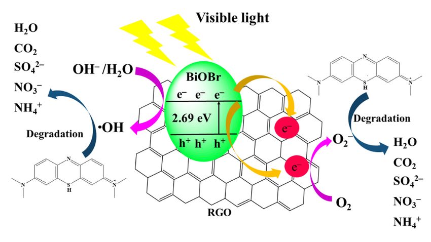
2.3. Synthesis of the BiOBr-G Nanocomposites
BiOBr-G nanocomposites with various GO weight percentages were synthesized
using the microwave-assisted method. Briefly, 0.4608 g Bi(NO3 )3 ·5H2 O was dissolved
in 25 mL of ethylene glycol, after which the mixture was dispersed in an ultrasonic bath
for 15 min. Simultaneously, GO powders were dissolved in 10 ml of ethylene glycol,
after which the mixture was subjected to magnetic stirring for 30 min. Subsequently,
0.2380 g of KBr was added to the Bi(NO3 )3 ·5H2 O solution, after which the mixture was
stirred at room temperature for 0.5 h. Thereafter, the GO solution was carefully added
to the afore-mentioned solution, and the solution was stirred continuously for 30 min.
Subsequently, the mixture was transferred into a 50 mL Teflon-lined vessel, and the mixture
was maintained at 90 ◦ C for 15 min. The precipitates were collected by centrifugation and
washed three times with DI water and ethanol. Thereafter, the precipitates were dried in an
oven at 80 ◦ C overnight. For comparison, pure BiOBr and RGO were also prepared using a
similar process. The BiOBr-G nanocomposites with RGO content of 0.5, 1, and 5 wt% were
labeled as BiOBr-G0.5, BiOBr-G1, and BiOBr-G5, respectively. The schematic illustration of
the synthesis process is shown in Figure 1.Materials 2021, 14, x FOR PEER REVIEW 4 of 15
°C overnight. For comparison, pure BiOBr and RGO were also prepared using a similar 148
Materials 2021, 14, 4577 process. The BiOBr-G nanocomposites with RGO content of 0.5, 1, and 5 wt% were labeled4 of 149
14
as BiOBr-G0.5, BiOBr-G1, and BiOBr-G5, respectively. The schematic illustration of the 150
synthesis process is shown in Figure 1. 151
152
Figure 1. Schematic illustration of the synthesis process of the BiOBr-G nanomaterial. 153
Figure 1. Schematic illustration of the synthesis process of the BiOBr-G nanomaterial. 154
2.4. Photocatalytic Activity
The photocatalytic
2.4. Photocatalytic Activity efficiency of the BiOBr-Gs nanocomposites was investigated. The 155
photocatalytic reactions of the nanocomposites were investigated using a PCX50B Discover
The photocatalytic efficiency of the BiOBr-Gs nanocomposites was investigated.
multi-channel photoreactor (Perfect Light Technology Ltd, Beijing, China). A 5 W white The 156
photocatalytic reactions of
light Light-emitting the lamp
diode nanocomposites
was used aswere investigated
the light source tousing
providea PCX50B Dis- with
visible light 157
covera multi-channel photoreactor (Perfect Light Technology Ltd, Beijing,
wavelength of above 420 nm. The MB used in this study was a model pollutant that China). A 5 W 158
whitemust
lightbe
Light-emitting diode lamp was used as the light source to provide
removed. To prepare the sample used for the photocatalytic analysis, 30 mg of visible light 159
with as-prepared
a wavelength of above 420 nm. The MB used in this study was a model
samples was weighed into a quartz flask, after which 50 mL of 2 × 10 M MB pollutant that
− 5 160
mustsolution
be removed. To prepare
was added. the sample
Subsequently, the used for was
solution the stirred
photocatalytic
in the darkanalysis, 30 mg
for 10 min of 161
to achieve
as-prepared samples was weighed into a quartz flask, after which 50 ml of
adsorption–desorption equilibrium, after which the solution was subjected to irradiation. 2×10 −5 M MB 162
solution was added. Subsequently, the solution was stirred in the dark for
The photocatalytic reaction was carried out under visible light irradiation for 75 min, and 10 min to 163
achieve adsorption–desorption equilibrium, after which the solution was
3 mL of the as-prepared solution was collected every 15 min. The collected MB solutions subjected to ir- 164
radiation. The photocatalytic reaction was carried out under visible
were centrifuged (14,000 RPM, 3 min) to remove the sample powder. The degradationlight irradiation for 165
75 min,
of MBandwas
3 mL of the as-prepared
evaluated by measuring solution was collectedabsorption
the characteristic every 15 min.of MB Thesolution
collected 166
at 664
MB solutions
nm usingwere centrifuged
a CT-2200 UV-vis(14000 RPM, 3 min) to
spectrophotometer remove theCo.
(ChromTech sample powder.
Ltd; Apple The MN,
Valley, 167
degradation of MB
USA). After was evaluated
measurement, thebycollected
measuring the characteristic
samples were re-injectedabsorption of MB solu-
to the quartz flask, and 168
tion at
the664 nm using acondition
experimental CT-2200 wasUV-vis spectrophotometer (ChromTech Co. Ltd; Apple 169
maintained.
Valley, MN, TheUSA ). After
removal measurement,
efficiency the collected
of the target pollutantsamples were re-injected
was determined using theto thefollow-
170
quartzingflask, and the experimental condition was maintained.
equation: 171
The removal efficiency of the target pollutant was Ct determined using the following 172
Removal (%) = 1 − × 100% (1)
equation: C0 173
C and concentration of MB at time t, respectively.
where C0 and Ct are the initial concentration
Removal % 1− 100% (1)
C
2.5. Characterization
where C0 and Ct are the initial concentration and concentration of MB at time t, respec- 174
The as-synthesized BiOBr-G nanocomposites were synthesized using a microwave
tively. 175
(Flexiwave T660, Milestone srl, Sorisole, Italy). The crystal structure of the as-synthesized
nanocomposites was analyzed using powder X-ray diffraction (XRD, D8A25 eco, BRUKER
2.5. Characterization 176
Co. Ltd, Billerica, MA, USA) with CuKα X-ray radiation (λ = 1.5418 Å) operated at 40 kV
and 25 mA. The morphology of the particles was observed using transmission electron
microscopy (TEM, Hitachi H-7500, Tokyo, Japan) at an accelerating voltage of 80 kV. The
surface morphology of the samples was investigated using scanning electron microscopy
(SEM, Jeolism -6930, Tokyo, Japan) equipped with a system of energy-dispersive spec-Materials 2021, 14, 4577 5 of 14
troscopy (EDS, INCAx act, Munich, Germany). The photoluminescence (PL, Hitachi
F-7000, Tokyo, Japan) spectra of the samples were obtained using a Hitachi F-7000 (Tokyo,
Japan) spectrometer at an emission wavelength of 300 nm. The Raman spectra were
determined using a Princeton Instruments Acton SP2500 (Acton, MA, USA) monochro-
matic/photographic spectrometer equipped with a nitrogen-cooled CCD detector and a
Spec-10 system. The light absorption properties of the samples were investigated using
UV−vis diffuse reflectance spectroscopy (DRS, JASCO IBXL0005-V770-EA, JASCO, Tokyo,
Japan). The chemical state of the composites was measured using Fourier-transform in-
frared spectrometer (FT-IR, JASCO FT/IR-6700, JASCO, Tokyo, Japan). A multi-channel
photochemical reaction system (Perfect Light Technology Ltd, PCX-50B, Beijing, China)
was used during the photocatalytic reaction experiment. The MB concentration was mea-
sured using a CT-2200 ultraviolet-visible (UV-Vis) spectrophotometer (ChromTech Co. Ltd.;
Apple Valley, MN, USA).
3. Results
3.1. Characterization of BiOBr and BiOBr-G
3.1.1. XRD Analysis
The GO, RGO, BiOBr, and the BiOBr-G nanocomposites synthesized using the microwave-
assisted method were analyzed using XRD (Figure 2). The XRD pattern of the GO exhibited
a distinct strong reflex at 2θ = 12.6◦ , corresponding to the (001) crystal plane of GO. In ad-
dition, notable peaks were observed in the XRD pattern of the RGO at 2θ = 25.0◦ and 43.1◦ ,
corresponding to the RGO (002) and (102) crystal plane, respectively [35]. However, the (001)
crystal plane of GO was not observed in the XRD pattern of the RGO, confirming the suc-
cessful reduction of GO by the microwave-assisted method. The XRD patterns of BiOBr and
BiOBr-G nanocomposites were consistent with the standard card number of pure tetragonal
phase BiOBr (JCPDS 09-0393) [36]. The main peaks of the XRD pattern were observed at
2θ = 10.9◦ , 25.3◦ , 31.7◦ , 32.3◦ , 39.3◦ , 46.3◦ , and 57.2◦ , corresponding to the (001), (101), (102),
(110), (112), (200), and (212) crystal planes, respectively [37]. However, the (001) crystal plane
of GO was not observed in the XRD patterns of all the BiOBr-G samples, confirming
Materials 2021, 14, x FOR PEER REVIEW the
6 of 15
successful reduction of GO. Furthermore, the typical diffraction peaks of RGO at 2θ = 25.0◦
and 43.1◦ were not observed in the XRD patterns of the BiOBr-G nanocomposites, which
could be attributed to the relatively low diffraction peak intensity of RGO [38].
218
219
220
221
222
223
224
225
Figure 2. The XRD spectra of GO, RGO, BiOBr, and BiOBr-G samples (Black arrow show a standard
Figure 2. The09-0393
card JCPDS XRD spectra
of pure of GO, RGO, BiOBr, and BiOBr-G samples (Black arrow show a 226
BiOBr).
standard card JCPDS 09-0393 of pure BiOBr). 227
3.1.2.Raman
3.1.2. RamanSpectrum
Spectrum 228
Figure 3 shows the Raman spectrum of GO, RGO, and BiOBr-G. Two notable bands,
Figure 3 shows the Raman spectrum of GO, RGO, and BiOBr-G. Two notable bands, 229
the D and G bands, were observed in the Raman spectra of GO and RGO, respectively. The
the D and G bands, were observed in the Raman spectra of GO and RGO, respectively. 3 230
D band corresponded to the k-point phonon mode, which could be attributed to the sp
The D band corresponded to the k-point phonon mode, which could be attributed to the 231
defects in the carbon material, such as vacancies and edge effect. The G band could be
sp3 defects in the carbon material, such as vacancies and edge effect. The G band could be 232
attributed to the sp2 carbon atoms vibration model [39,40]. The D and G bands of GO were 233
observed at 1348 cm−1 and 1587 cm−1, respectively. In addition, the D and G bands of RGO 234
were observed at 1343 cm−1 and 1572 cm−1, respectively. However, no notable peak was 235
observed in the Raman spectrum of BiOBr. In addition, two bands were observed in the 236Figure 3 shows the Raman spectrum of GO, RGO, and BiOBr-G. Two notable bands, 229
the D and G bands, were observed in the Raman spectra of GO and RGO, respectively. 230
The D band corresponded to the k-point phonon mode, which could be attributed to the 231
sp3 defects in the carbon material, such as vacancies and edge effect. The G band could be 232
attributed to the sp2 carbon atoms vibration model [39,40]. The D and G bands of GO were 233
Materials 2021, 14, 4577 6 of 14
observed at 1348 cm−1 and 1587 cm−1, respectively. In addition, the D and G bands of RGO 234
were observed at 1343 cm−1 and 1572 cm−1, respectively. However, no notable peak was 235
observed in the Raman spectrum of BiOBr. In addition, two bands were observed in the 236
2 carbon atoms vibration model
Raman spectrum
attributed of sp
to the BiOBr-G at 1365 and 1601 cm−1. The D band
[39,40]. ThetoDGand
band intensity
G bands ratio
of GO were237
observed(Iat − 1 −1 , respectively. In addition, the D and G bands of RGO
of BiOBr-G D/I1348 cm was
G = 0.99) andslightly
1587 cmlower than that of the pure GO (ID/IG = 1.01). This 238
were observed at 1343 cmsp−13 and 1572 cm−1 , respectively. However, no notable peak was
confirms the decrease in the domain of the carbon atoms in BiOBr-G and the increase 239
in the production of the graphene sp2ofstructure
observed in the Raman spectrum BiOBr. Ininaddition,
BiOBr-G.two bands were
According to theobserved in the240
literature,
Raman spectrum of BiOBr-G at 1365 and 1601 cm −1 . The D band to G band intensity ratio
these results correspond to the high electron transport rate of BiOBr-G [41,42]. In addition, 241
the of
ID/IBiOBr-G
G value of(IDBiOBr-G
/IG = 0.99) waswas slightly
higher than lower
that than that(Iof
of RGO D/Ithe
G = pure
0.89),GO (ID /IG =that
indicating 1.01).
theThis242
confirms the decrease in the 3 domain of the carbon atoms in BiOBr-G and the increase
spdefects
RGO loaded with BiOBr has more than RGO. The shift of the D and G band in the 243
in theRaman
BiOBr-G production of the
spectrum graphenethat
confirmed sp2thestructure in BiOBr-G. According
microwave-assisted to the literature,
synthesis achieved both 244
these results correspond to the high electron
the reduction of GO and the formation of Bi-OBr-G [24,43]. transport rate of BiOBr-G [41,42]. In addition, 245
the ID /IG value of BiOBr-G was higher than that of RGO (ID /IG = 0.89), indicating that the246
RGO loaded with BiOBr has more defects than RGO. The shift of the D and G band in the247
BiOBr-G Raman spectrum confirmed that the microwave-assisted synthesis achieved both248
the reduction of GO and the formation of Bi-OBr-G [24,43]. 249
250
251
252
253
254
255
256
257
258
259
Figure 3. Raman spectra of the GO, RGO, BiOBr, and BiOBr-G nanocomposites. ID / IG is the ratio of
the integrated intensities of the D and G bands.
3.1.3. FTIR Spectroscopy
The FT-IR spectra of BiOBr and BiOBr-G nanocomposites are shown in Figure 4. A
notable band was observed in the FT-IR spectra of the BiOBr nanosheets at 514 cm−1 ,
which could be attributed to the typical symmetric A2u type of the Bi–O bond vibrations.
In addition, a similar band was observed in the FT-IR spectra of the BiOBr-G nanocom-
posite [44,45]. Furthermore, a wider absorption band was observed in the FT-IR spectra
of these samples at 3404 cm−1 , which could be attributed to the O–H stretching mode of
adsorbed water or hydroxyl groups [46,47]. Moreover, the BiOBr-G sample exhibited the
typical FT-IR spectrum of BiOBr-G. This indicates that the addition of GO to BiOBr during
the microwave-assisted synthesis had no effect on the crystal structure of BiOBr [48].
3.1.4. Morphological Characterization
Figure 5a,b show the SEM image of BiOBr and BiOBr-G nanocomposites. The pure
BiOBr exhibited a thin flake structure with a two-dimensional relatively smooth surface,
which was assembled to flower-like microstructures [49]. However, the BiOBr-G nanocom-
posite exhibited a spherical structure formed by the assembly of smaller and denser
nanosheets. This indicates that the addition of RGO affected the crystallization process of
BiOBr and destroyed the existing micro-flower nanostructure of BiOBr, thus increasing the
dispersion and photocatalytic activity of BiOBr-G [50]. Furthermore, TEM was conducted
to investigate the structural characteristics of the BiOBr and BiOBr-G nanocomposites,
and the results are shown in Figure 5c, d. As shown in Figure 5c, BiOBr exhibits a thin
sheet stacked structure with a flat surface, which is consistent with the SEM results and
observation [51]. After the addition of RGO, the particle size of BiOBr reduced significantly,
and the dispersion on the wrinkled RGO increased. This indicated the successful prepara-3.1.3. FTIR Spectroscopy 262
The FT-IR spectra of BiOBr and BiOBr-G nanocomposites are shown in Figure 4. A 263
notable band was observed in the FT-IR spectra of the BiOBr nanosheets at 514 cm−1, which 264
could be attributed to the typical symmetric A2u type of the Bi–O bond vibrations. In ad- 265
Materials 2021, 14, 4577 7 of 14
dition, a similar band was observed in the FT-IR spectra of the BiOBr-G nanocomposite 266
[44,45]. Furthermore, a wider absorption band was observed in the FT-IR spectra of these 267
samples at 3404 cm−1, which could be attributed to the O–H stretching mode of adsorbed 268
water
tion or
ofhydroxyl
BiOBr-G.groups
This is[46,47].
because Moreover, the BiOBr-G
RGO effectively sample exhibited
controlled thesize
the crystal typical FT- and
of BiOBr 269
IRprevented
spectrum the
of BiOBr-G. This indicates that the addition of GO to BiOBr during the
agglomeration of nanoparticles [52]. In addition, after the addition of RGO, mi- 270
crowave-assisted synthesis had no effect on the crystal structure of BiOBr [48].
the surface area of the BiOBr-G nanocomposite in contact with dye increased compared271 to
that of pure BiOBr owing to its smaller particle size. Consequently, the electron transfer
272
and photocatalytic activity of BiOBr were significantly enhanced [53].
273
274
275
276
277
278
279
280
Materials 2021, 14, x FOR PEER REVIEW 8 of 15
281
Figure 4. The FTIR spectrum of BiOBr and BiOBr-G nanocomposites.
Figure 4. The FTIR spectrum of BiOBr and BiOBr-G nanocomposites. 282
3.1.4. Morphological Characterization 283
Figure 5a, b show the SEM image of BiOBr and BiOBr-G nanocomposites. The pure 284
BiOBr exhibited a thin flake structure with a two-dimensional relatively smooth surface, 285
which was assembled to flower-like microstructures [49]. However, the BiOBr-G nano- 286
composite exhibited a spherical structure formed by the assembly of smaller and denser 287
nanosheets. This indicates that the addition of RGO affected the crystallization process of 288
BiOBr and destroyed the existing micro-flower nanostructure of BiOBr, thus increasing 289
the dispersion and photocatalytic activity of BiOBr-G [50]. Furthermore, TEM was con- 290
ducted to investigate the structural characteristics of the BiOBr and BiOBr-G nanocompo- 291
sites, and the results are shown in Figure 5c, d. As shown in Figure 5c, BiOBr exhibits a 292
thin sheet stacked structure with a flat surface, which is consistent with the SEM results 293
and observation [51]. After the addition of RGO, the particle size of BiOBr reduced signif- 294
icantly, and the dispersion on the wrinkled RGO increased. This indicated the successful 295
preparation of BiOBr-G. This is because RGO effectively controlled the crystal size of Bi- 296
OBr and prevented the agglomeration of nanoparticles [52]. In addition, after the addition 297
of RGO, the surface area of the BiOBr-G nanocomposite in contact with dye increased 298 301
compared to that of pure BiOBr owing to its smaller particle size. Consequently, the elec- 299
Figure5.5.SEM
SEM imagesofof(a)
(a)BiOBr
BiOBrand
and (b)BiOBr-G.
BiOBr-G.TEM
TEMimages
imagesofof(c)
(c)BiOBr
BiOBrand
and(d)
(d) BiOBr-G. 302
tron transfer andimages
Figure photocatalytic activity(b)
of BiOBr were significantly enhanced [53]. BiOBr-G. 300
3.1.5.
3.1.5.UV-Vis
UV-visDiffuse
DiffuseReflectance
ReflectanceSpectra
Spectra 303
Figure
Figure 6a shows the UV-Vis diffusereflectance
6a shows the UV-Vis diffuse reflectancespectra
spectra(DRS)
(DRS)results
resultsofofBiOBr
BiOBrand
and 304
BiOBr-G nanocomposites. As shown in the image, both BiOBr and BiOBr-G
BiOBr-G nanocomposites. As shown in the image, both BiOBr and BiOBr-G exhibit exhibit a
a wide 305
wide and high absorption in the visible light range. In addition, the absorption peak of
and high absorption in the visible light range. In addition, the absorption peak of BiOBr 306
BiOBr was observed at 445 nm. After adding RGO, the BiOBr-G absorption edge slightly
was observed at 445 nm. After adding RGO, the BiOBr-G absorption edge slightly red- 307
red-shifted to 462 nm. The optical band gap (Eg ) of the BiOBr and BiOBr-G composites was
shifted to 462 nm. The optical band gap (Eg) of the BiOBr and BiOBr-G composites was 308
obtained using the Tauc relation, as follows [54]:
obtained using the Tauc relation, as follows [54]: 309
n/2n/2
= A(hν
αhναhν − E−g )Eg)
= A(hν (2)
(2)
whereAAisisa constant,
where a constant, which
which depends
depends on on
the the transition
transition probability;
probability; h isPlanck
h is the the Planck con-
constant; 310
νstant;
is theνfrequency
is the frequency
of light;ofαlight;
is theαabsorption
is the absorption coefficient;
coefficient; and n isand n ison
based based on the
the transi- 311
transition
tion property
property of the of the semiconductor
semiconductor [55].example,
[55]. For For example,
n = 2ncorresponds
= 2 corresponds to indirect
to the the indi- 312
rect transition of the semiconductor, whereas n = 1/2 corresponds to the direct transition 313
of the semiconductor. Previous studies have reported that the n of BiOBr is 2, indicating 314
that the transition property of BiOBr is indirect [56]. The plot of (αhν)1/2 vs. the photon 315
energy is shown in Fig. 6b. As shown in the image, the Eg value of the BiOBr and BiOBr- 316obtained using the Tauc relation, as follows [54]: 309
αhν = A(hν − Eg)n/2 (2)
where A is a constant, which depends on the transition probability; h is the Planck con- 310
Materials 2021, 14, 4577 stant; ν is the frequency of light; α is the absorption coefficient; and n is based on the 8 of 14311
transition property of the semiconductor [55]. For example, n = 2 corresponds to the indi- 312
rect transition of the semiconductor, whereas n = 1/2 corresponds to the direct transition 313
of the semiconductor. Previous studies have reported that the n of BiOBr is 2, indicating 314
transition of the semiconductor, whereas n = 1/2 corresponds to the direct transition of
that the transition property of BiOBr is indirect [56]. The plot of (αhν)1/2 vs. the photon 315
the semiconductor. Previous studies have reported that the n of BiOBr is 2, indicating
energy is shown in Fig. 6b. As shown in the image, the Eg value of the BiOBr and BiOBr- 316
that the transition property of BiOBr is indirect [56]. The plot of (αhν)1/2 vs. the photon
G nanocomposites are 2.83 and 2.69 eV, respectively. The Eg value of the BiOBr is similar 317
energy is shown in Fig. 6b. As shown in the image, the Eg value of the BiOBr and BiOBr-G
to the previous study [24]. 318
nanocomposites are 2.83 and 2.69 eV, respectively. The Eg value of the BiOBr is similar to
319
the previous study [24].
320
321
322
323
324
325
326
327
328
329
330
Materials 2021, 14, x FOR PEER REVIEW 9 of 15 331
332
333
Figure 6. (a) Diffuse Figure 6. (a)spectra
reflectance Diffuse(DRS)
reflectance spectra
and (b) Tauc(DRS)
plots and (b)BiOBr
of the Tauc plots of the BiOBr
and BiOBr-G and BiOBr-G nano-
nanocomposites. 335
334
composites. 336
3.1.6. PL Analysis
3.1.6. PL Analysis 337
The PL spectra of BiOBr and BiOBr-G were obtained to investigate their electron–hole
The PL spectra
recombination of BiOBrWith
properties. and BiOBr-G
an increasewereinobtained to investigate
the PL intensity their electron–
of a sample, 338
its photon
hole recombination properties. With an increase in the PL intensity of a sample,
separation rate decreases, thus increasing the electron–hole pair recombination. Conse-its photon 339
separation rate decreases, thus increasing the electron–hole pair recombination.
quently, this reduces the photocatalytic activity of the sample [57]. Figure 7 shows the Conse- 340
quently, this reduces the photocatalytic activity of the sample [57]. Figure
PL spectrum of the as-synthesized BiOBr and BiOBr-G nanocomposites at an exciting 7 shows the PL 341
spectrum of the as-synthesized BiOBr and BiOBr-G nanocomposites at an exciting
wavelength (λex ) of 300 nm. The highest peaks of BiOBr and BiOBr-G were observed at wave- 342
length (λex) of 300 nm. The highest peaks of BiOBr and BiOBr-G were observed at 468 nm. 343
468 nm. However, the PL spectral intensity of the pure BiOBr was significantly stronger
However, the PL spectral intensity of the pure BiOBr was significantly stronger than that 344
than that of BiOBr-G. With an increasing in the RGO content, the intensity of the BiOBr-G
of BiOBr-G. With an increasing in the RGO content, the intensity of the BiOBr-G emission 345
emission peak decreased, indicating that the addition of RGO enhanced the separation
peak decreased, indicating that the addition of RGO enhanced the separation of carriers. 346
of carriers. These results confirmed that photoelectrons moved from BiOBr to RGO and
These results confirmed that photoelectrons moved from BiOBr to RGO and that RGO 347
that RGO facilitated the suppression of the electron–hole pair recombination [58]. This
facilitated the suppression of the electron–hole pair recombination [58]. This indicates that 348
indicates that a higher quantum efficiency can be achieved during photocatalytic reactions
a higher quantum efficiency can be achieved during photocatalytic reactions by utilizing 349
by utilizing the hierarchical structure of BiOBr-G.
the hierarchical structure of BiOBr-G. 350
351
352
353
354
355
356
357
358
359
360
361
362
363
364
365
366
367
Figure 7. PL spectra of the as-synthesized samples. λ is the wavelength of fluorescence excitation.
Figure 7. PL spectra of the as-synthesized samples. λex isexthe wavelength of fluorescence excitation 368
3.2. Photocatalytic Activity 369
To investigate the photocatalytic properties of the fabricated samples, the MB degra- 370
dation properties of commercial TiO2 (P25), BiOBr, and each BiOBr-G sample under visi- 371
ble light were investigated (Figure 8a). The results revealed that the pure MB did not ex- 372Materials 2021, 14, 4577 9 of 14
3.2. Photocatalytic Activity
To investigate the photocatalytic properties of the fabricated samples, the MB degra-
dation properties of commercial TiO2 (P25), BiOBr, and each BiOBr-G sample under visible
light were investigated (Figure 8a). The results revealed that the pure MB did not exhibit
self-degrading properties under visible light; however, the addition of the photocatalyst
significantly improved the removal efficiency [59]. The order of MB removal percentage of
each material was: TiO2 P25 (29.74%) < BiOBr (67.25%) < BiOBr-G0.5 (71.37%) < BiOBr-G1
(90.80%) < BiOBr-G5 (96.41%). The photocatalytic activity of P25 under visible light was
lower than those of the other samples, which could be attributed to the fact that the band
gap of P25 is higher than that of BiOBr and BiOBr-Gs. This indicates that the P25 sample
exhibited the lowest MB removal rate compared to the other samples. In addition, the
photocatalytic activity of all the BiOBr-G nanocomposites was significantly higher than that
of BiOBr. These findings are consistent with the PL spectra in Figure 7. Furthermore, the
photoelectron–hole pair separation efficiency of the BiOBr-G sample was higher than that
of the BiOBr sample, and it also exhibited an optimum photocatalytic activity performance.
Materials 2021, 14, x FOR PEER REVIEW 10 of 15
The addition of RGO to BiOBr significantly enhanced the photocatalytic activity of BiOBr,
with the optimum RGO concentration being 5 wt%. In addition, the photo-induced electron
transfer rate from the BiOBr surface to the RGO surface increased with an increase in the
RGO loading,
induced electronthus increasing
transfer the the
rate from photocatalytic
BiOBr surface activity
to theofRGO
the BiOBr-G nanocomposite.
surface increased with 386
anThe prepared
increase photocatalyst
in the RGO loading, follows the first-order
thus increasing kinetic model (Figure
the photocatalytic activity8b), which
of the can be
BiOBr-G 387
expressed using
nanocomposite. theprepared
The followingphotocatalyst
equation [60]:follows the first-order kinetic model (Figure 388
8b), which can be expressed using the following equation [60]: 389
C C0 = kt
−ln− ln=Ckt (3)
(3)
C t
where
wherek k andandt are thethe
t are raterate
constant andand
constant lighting time,time,
lighting respectively. The kThe
respectively. values of P25,of
k values 390
BiOBr, BiOBr-G0.5,
P25, BiOBr, BiOBr-G1,
BiOBr-G0.5, and BiOBr-G5
BiOBr-G1, are 0.00426,
and BiOBr-G5 0.0090, 0.0313,
are 0.00426, 0.0090,0.0370,
0.0313,and 0.0392
0.0370, and 391
min −1, respectively.
0.0392 The increase
min−1 , respectively. Theinincrease
the k value
in theof kBiOBr-G
value ofcompared
BiOBr-G to that of BiOBr
compared in-of
to that 392
dicates
BiOBrthe short-term
indicates degradation
the short-term of MB dye.
degradation of MBIn addition, the BiOBr-G5
dye. In addition, nanocomposite
the BiOBr-G5 nanocom- 393
exhibited the optimum photocatalytic effect, which was 4.36 times
posite exhibited the optimum photocatalytic effect, which was 4.36 times higher higher than that
thanof Bi-of
that 394
OBr. This result indicates that the addition of graphene to BiOBr significantly
BiOBr. This result indicates that the addition of graphene to BiOBr significantly improved improved 395
the
thephotocatalytic
photocatalytic efficiency
efficiency ofofBiOBr
BiOBr[61]. Table
[61]. Table 1 shows
1 shows the
thecomparison
comparison ofof
the MB
the MB re-re- 396
moval
movaland andrate
rateconstant
constantofofBiOBr-G5
BiOBr-G5to to those
those of different materials
materialsinvestigated
investigatedininprevious
previ- 397
ous studies.
studies. TheThe MB-removal
MB-removal percentageofofBiOBr-G5
percentage BiOBr-G5was wassimilar
similartotothat
thatofofother
othermaterials;
materi- 398
als; however,
however, thethe rate
rate constant
constant of BiOBr-G5
of BiOBr-G5 waswas higher
higher thanthan those
those of the
of the other
other materials.
materials. This 399
This result
result illustrates
illustrates the the enhanced
enhanced MB-removal
MB-removal efficiency
efficiency of BiOBr-G5.
of BiOBr-G5. 400
401
402
Figure 8. (a) Photocatalytic degradation of MB by P25, BiOBr, and BiOBr-Gs. (b) Photocatalytic kinetic of P25, BiOBr,
and BiOBr-Gs. Figure 8. (a) Photocatalytic degradation of MB by P25, BiOBr, and BiOBr-Gs. (b) Photocatalytic 403
kinetic of P25, BiOBr, and BiOBr-Gs. 404
Table 1. MB removal rate and kinetic constant of various catalysts reported in previous studies. 405
Rate Con-
atalyst MB Removal (%) References
stant (min−1)Materials 2021, 14, 4577 10 of 14
Table 1. MB removal rate and kinetic constant of various catalysts reported in previous studies.
Atalyst MB Removal (%) Rate Constant (min−1 ) References
BiOBr-G5 96.41 0.0392 This work
NiFe2 O4 -RGO 99.1 0.0199 [20]
Ag-ZnO ~100 — [27]
Ag/TiO2 36~90 0.001~0.008 [28]
BG-6 100 0.0087 [31]
NiFe0.5 Nd1.5 O4 93.4 — [62]
MnFe2 O4 -graphene ~99 0.0097 [63]
WO3 /g-C3 N4 95 0.01897 [64]
Fe2 TiO5 ~100 0.016 [65]
T-BVO-600 98.93 0.0184 [66]
3.3. Photocatalytic Mechanisms
Figure 9 shows the photocatalysis mechanism of BiOBr-G under visible light irradia-
tion. The excitation of the electrons (e− ) of the VB into the CB under visible light irradiation
leads to the generation of electron–hole pairs. The ECB and EVB of BiOBr were evaluated
using the equation below [67]:
EVB = χ − Ee + 0.5Eg (4)
Materials 2021, 14, x FOR PEER REVIEW 12 of 15
ECB = EV − Eg (5)
434
Thephotocatalytic
Figure9.9.The
Figure photocatalyticmechanism
mechanismdiagram.
diagram. 435
According to the DRS measurements, Ee is 4.5 eV, and it represents the energy of free
4. Conclusions 436
electrons on the hydrogen scale. In addition, EVB and ECB correspond to the edge potentials
In summary, in this study, BiOBr-G nanocomposites were successfully synthesized 437
of VB and CB, respectively. From the DRS results, χ is semiconductor electronegativity.
using a facile one-step microwave-assisted method and characterized by XRD, Raman, 438
The χ of BiOBr was 6.17 eV, and the Eg of BiOBr-G was 2.69 eV. Using the afore-mentioned
FTIR, SEM, TEM, UV-vis DRS, and PL. The XRD analysis confirmed the successful syn- 439
equation, the EVB and ECB of BiOBr are approximately 3.02 and 0.33 eV, respectively [68].
thesis of GO, RGO, BiOBr, and all the BiOBr-G nanocomposites. However, the RGO dif- 440
The VB position of BiOBr is above OH− /•OH (2.38 eV to Normal Hydrogen Electrode,
fraction peak was not observed in the XRD pattern of BiOBr-G. In electron-hole
NHE) and H2 O/•OH (2.72 eV to NHE) [69]. The photogenerated addition, D and G bands
of BiOBr can 441
were observed− in the Raman spectrum of the BiOBr-G nanocomposites,
oxidize OH and H2 O to the •OH free radicals, and •OH can degrade the MB molecules. indicating the 442
grapheneThe structure
RGO exhibitsof the
ansynthesized nanocomposite.
extremely efficient Furthermore,
electron collection a Bi–O vibrational
and separation structure. 443
peak was observed in the FT-IR spectra of BiOBr and Bi-OBr-G. The
After the charge separation of BiOBr, the excited electrons were transferred SEM and TEM results
to the RGO 444
revealed that the presence of RGO in the BiOBr-G nanocomposites prevented
surface, thus decreasing the rate of electron–hole recombination [70]. Photogenerated the nano- 445
particles’
electronsagglomeration
reacted with and reduced the
O2 molecules particle size.
adsorbed In addition,
on the thethe
surface of band
RGOgaptoofproduce
BiOBr- 446
GOwas lower than
− radicals. that of BiOBr, indicating
− that the addition of RGO to BiOBr
Simultaneously, the OH and H2 O reacted with the holes in the VB, thus enhanced 447
2
the photocatalytic
generating activity of
•OH radicals. BiOBr.
The RGOThe PL results
nanosheets revealedthe
enhanced that BiOBr-G exhibited
electron–hole higher
pair separation 448
quantum efficiency during the photocatalytic process compared to BiOBr. The photocata- 449
lytic activity of the as-synthesized nanocomposites under visible light irradiation was in- 450
vestigated. BiOBr-G5 exhibited the optimum photocatalytic activity, and the removal per- 451
centage of MB achieved more than 96% in 75 min. The prepared photocatalyst follows the 452
first-order kinetic model, and the rate constant of BiOBr-G5 (0.0392 min−1) was higher than 453Materials 2021, 14, 4577 11 of 14
and also increased the adsorption of reactants owing to π–π interactions and electrostatic
force effects. In addition, the high surface area of RGO facilitated the adsorption of MB
and the active oxides (O2 − and •OH radicals), thus enhancing the contact probability with
radical and dye molecules and enhancing the photocatalytic activity of the catalyst. Finally,
the MB molecules were degraded by O2 − and •OH radicals, thus producing non-toxic
small molecules (H2 O, CO2 , SO4 2− , NO3 − , and NH4 + ). This photocatalytic process can be
represented using the following chemical equation [20,71].
BiOBr + hν → e− (BiOBr) + h+ (BiOBr) (6)
e − + O2 → O2 − (7)
h+ + OH− /H2 O → •OH (8)
h+ / O2 − / •OH + C16 H18 N3 ClS → H2 O + CO2 + SO4 2− + NO3 − + NH4 + (9)
4. Conclusions
In summary, in this study, BiOBr-G nanocomposites were successfully synthesized us-
ing a facile one-step microwave-assisted method and characterized by XRD, Raman, FTIR,
SEM, TEM, UV-vis DRS, and PL. The XRD analysis confirmed the successful synthesis
of GO, RGO, BiOBr, and all the BiOBr-G nanocomposites. However, the RGO diffraction
peak was not observed in the XRD pattern of BiOBr-G. In addition, D and G bands were
observed in the Raman spectrum of the BiOBr-G nanocomposites, indicating the graphene
structure of the synthesized nanocomposite. Furthermore, a Bi–O vibrational peak was
observed in the FT-IR spectra of BiOBr and Bi-OBr-G. The SEM and TEM results revealed
that the presence of RGO in the BiOBr-G nanocomposites prevented the nanoparticles’
agglomeration and reduced the particle size. In addition, the band gap of BiOBr-G was
lower than that of BiOBr, indicating that the addition of RGO to BiOBr enhanced the photo-
catalytic activity of BiOBr. The PL results revealed that BiOBr-G exhibited higher quantum
efficiency during the photocatalytic process compared to BiOBr. The photocatalytic activity
of the as-synthesized nanocomposites under visible light irradiation was investigated.
BiOBr-G5 exhibited the optimum photocatalytic activity, and the removal percentage of
MB achieved more than 96% in 75 min. The prepared photocatalyst follows the first-order
kinetic model, and the rate constant of BiOBr-G5 (0.0392 min−1 ) was higher than those of
the other materials. These results were also superior to those of various catalysts reported
in previous studies. The BiOBr-G nanocomposite synthesized in this study is an efficient,
cost-effective, and environmentally friendly photocatalyst, with promising potential for
wastewater treatment.
Author Contributions: K.-Y.S. conceptualized the idea and designed the experiments; Y.-L.K. per-
formed the experiments; K.-Y.S., Y.-L.K., and E.-R.W. analyzed the data; K.-Y.S. funding acquisition;
K.-Y.S., Y.-L.K., and E.-R.W. explained and visualized the data and wrote the manuscript. All authors
have read and agreed to the published version of the manuscript.
Funding: This work was financially supported by the National Pingtung University of Taiwan (Grant
No. NPTU-110-002 and Grant No. NPTU-110-009).
Institutional Review Board Statement: Not applicable.
Informed Consent Statement: Not applicable.
Data Availability Statement: All the data are available within the manuscript.
Conflicts of Interest: The authors declare no conflict of interest.Materials 2021, 14, 4577 12 of 14
References
1. Wang, Y.; Long, Y.; Yang, Z.; Zhang, D. A novel ion-exchange strategy for the fabrication of high strong BiOI/BiOBr heterostructure
film coated metal wire mesh with tunable visible-light-driven photocatalytic reactivity. J. Hazard. Mater. 2018, 351, 11–19.
[CrossRef]
2. Guo, L.; Han, X.; Zhang, K.; Zhang, Y.; Zhao, Q.; Wang, D.; Fu, F. In-Situ Construction of 2D/2D ZnIn2 S4 /BiOCl Heterostructure
with Enhanced Photocatalytic Activity for N2 Fixation and Phenol Degradation. Catalysts 2019, 9, 729. [CrossRef]
3. Das, T.K.; Ganguly, S.; Bhawal, P.; Mondal, S.; Das, N.C. A facile green synthesis of silver nanoparticle-decorated hydroxyapatite
for efficient catalytic activity towards 4-nitrophenol reduction. Res. Chem. Intermed. 2017, 44, 1189–1208. [CrossRef]
4. Wang, B.; An, W.; Liu, L.; Chen, W.; Liang, Y.; Cui, W. Novel Cu2S quantum dots coupled flower-like BiOBr for efficient
photocatalytic hydrogen production under visible light. RSC Adv. 2014, 5, 3224–3231. [CrossRef]
5. Wang, D.; Liu, L.; Wang, Y.; Fan, C.; Huang, W. A new insight on the role of CQDs in driving BiOBr into broader-spectrum-
response: Dual function of up-conversion and photosensitization effect. Chem. Phys. Lett. 2020, 747, 137340. [CrossRef]
6. Qu, X.; Liu, M.; Li, L.; Wang, R.; Sun, H.; Shi, L.; Du, F. BiOBr flakes decoration and structural modification for CdTe/TiO2
spheres: Towards water decontamination under simulated light irradiation. Mater. Sci. Semicond. Process. 2019, 93, 331–338.
[CrossRef]
7. Lv, J.; Hu, Q.; Cao, C.; Zhao, Y. Modulation of valence band maximum edge and photocatalytic activity of BiOX by incorporation
of halides. Chemosphere 2018, 191, 427–437. [CrossRef]
8. Zhang, D.; Li, J.; Wang, Q.; Wu, Q. High {001} facets dominated BiOBr lamellas: Facile hydrolysis preparation and selective
visible-light photocatalytic activity. J. Mater. Chem. A 2013, 1, 8622–8629. [CrossRef]
9. Dashairya, L.; Sharma, M.; Basu, S.; Saha, P. SnS2/RGO based nanocomposite for efficient photocatalytic degradation of toxic
industrial dyes under visible-light irradiation. J. Alloy Compd. 2019, 774, 625–636. [CrossRef]
10. Shivakumara, C.; Saraf, R.; Halappa, P. White luminescence in Dy 3+ doped BiOCl phosphors and their Judd–Ofelt analysis. Dye.
Pigment. 2016, 126, 154–164. [CrossRef]
11. Zhao, Z.Y.; Dai, W.W. Structural, Electronic, and Optical Properties of Eu-Doped BiOX (X = F, Cl, Br, I): A DFT+U Study. Inorg.
Chem 2014, 53, 13001–13011. [CrossRef]
12. Zhang, S.; Yang, J. Microwave-Assisted Synthesis of BiOCl/BiOBr Composites with Improved Visible-Light Photocatalytic
Activity. Ind. Eng. Chem. Res. 2015, 54, 9913–9919. [CrossRef]
13. Liu, Y.; Xu, J.; Wang, L.; Zhang, H.; Xu, P.; Duan, X.; Sun, H.; Wang, S. Three-Dimensional BiOI/BiOX (X = Cl or Br) Nanohybrids
for Enhanced Visible-Light Photocatalytic Activity. Nanomaterials 2017, 7, 64. [CrossRef] [PubMed]
14. Meng, X.; Li, Z.; Chen, J.; Xie, H.; Zhang, Z. Enhanced visible light-induced photocatalytic activity of surface-modified BiOBr
with Pd nanoparticles. Appl. Surf. Sci. 2018, 433, 76–87. [CrossRef]
15. Vadivel, S.; Paul, B.; Maruthamani, D.; Kumaravel, M.; Vijayaraghavan, T.; Hariganesh, S.; Pothu, R. Synthesis of yttrium doped
BiOF/RGO composite for visible light: Photocatalytic applications. Mater. Sci. Energy Technol. 2019, 2, 112–116. [CrossRef]
16. Gao, J.; Gao, Y.; Sui, Z.; Dong, Z.; Wang, S.; Zou, D. Hydrothermal synthesis of BiOBr/FeWO4 composite photocatalysts and their
photocatalytic degradation of doxycycline. J. Alloy Compd. 2018, 732, 43–51. [CrossRef]
17. Liu, T.; Wang, Y. Synergistic effect of iodine doping and platinum loading on boosting the visible light photocatalytic activity of
BiOBr. Inorg. Chem. Commun. 2020, 114, 107846. [CrossRef]
18. Ganguly, S.; Das, P.; Bose, M.; Das, T.K.; Mondal, S.; Das, A.K.; Das, N.C. Sonochemical green reduction to prepare Ag
nanoparticles decorated graphene sheets for catalytic performance and antibacterial application. Ultrason. Sonochemistry 2017, 39,
577–588. [CrossRef]
19. Gomez-Ruiz, B.; Ribao, P.; Diban, N.; Rivero, M.; Ortiz, I.; Urtiaga, A. Photocatalytic degradation and mineralization of
perfluorooctanoic acid (PFOA) using a composite TiO2 −rGO catalyst. J. Hazard. Mater. 2018, 344, 950–957. [CrossRef]
20. Liang, J.; Wei, Y.; Zhang, J.; Yao, Y.; He, G.; Tang, B.; Chen, H. Scalable Green Method to Fabricate Magnetically Separable
NiFe2O4-Reduced Graphene Oxide Nanocomposites with Enhanced Photocatalytic Performance Driven by Visible Light. Ind.
Eng. Chem. Res. 2018, 57, 4311–4319. [CrossRef]
21. Liu, J.; Wang, Z.; Liu, L.; Chen, W. Reduced graphene oxide as capturer of dyes and electrons during photocatalysis: Surface
wrapping and capture promoted efficiency. Phys. Chem. Chem. Phys. 2011, 13, 13216–13221. [CrossRef]
22. Patil, S.S.; Mail, M.G.; Hassan, M.A.; Patil, D.R.; Kolekar, S.S.; Ryu, S.W. One-Pot in Situ Hydrothermal Growth of BiVO4/Ag/rGO
Hybrid Architectures for Solar Water Splitting and Environmental Remediation. Sci. Rep. 2017, 7, 8404. [CrossRef] [PubMed]
23. Lee, J.; Dong, X.; Dong, X. Ultrasonic synthesis and photocatalytic characterization of H3PW12O40/TiO2 (anatase). Ultrason.
Sonochem. 2010, 17, 649–653. [CrossRef] [PubMed]
24. Vadivel, S.; Keerthi, P.; Vanitha, M.; Muthukrishnaraj, A.; Balasubramanian, N. Solvothermal synthesis of Sm-doped BiOBr/RGO
composite as an efficient photocatalytic material for methyl orange degradation. Mater. Lett. 2014, 128, 287–290. [CrossRef]
25. Behera, A.; Kandi, D.; Mansingh, S.; Martha, S.; Parida, K. Facile synthesis of ZnFe2O4@RGO nanocomposites towards
photocatalytic ciprofloxacin degradation and H2 energy production. J. Colloid Interface Sci. 2019, 556, 667–679. [CrossRef]
26. Farhadian, N.; Akbarzadeh, R.; Pirsaheb, M.; Jen, T.-C.; Fakhri, Y.; Asadi, A. Chitosan modified N, S-doped TiO2 and N, S-doped
ZnO for visible light photocatalytic degradation of tetracycline. Int. J. Biol. Macromol. 2019, 132, 360–373. [CrossRef] [PubMed]Materials 2021, 14, 4577 13 of 14
27. Arab Chamjangali, M.; Bagherian, G.; Javid, A.; Boroumand, S.; Farzaneh, N. Synthesis of Ag-ZnO with multiple rods (multi-
pods) morphology and its application in the simultaneous photo-catalytic degradation of methyl orange and methylene blue.
Spectrochim. Acta A Mol. Biomol. Spectrosc. 2015, 150, 230–237. [CrossRef]
28. Kumar, R.; Rashid, J.; Barakat, M. Zero valent Ag deposited TiO2 for the efficient photocatalysis of methylene blue under UV-C
light irradiation. Colloid Interface Sci. Commun. 2015, 5, 1–4. [CrossRef]
29. Liang, J.; Liu, F.; Li, M.; Liu, W.; Tong, M. Facile synthesis of magnetic Fe3O4@BiOI@AgI for water decontamination with visible
light irradiation: Different mechanisms for different organic pollutants degradation and bacterial disinfection. Water Res. 2018,
137, 120–129. [CrossRef]
30. Shenawi-Khalil, S.; Uvarov, V.; Fronton, S.; Popov, I.; Sasson, Y. A Novel Heterojunction BiOBr/Bismuth Oxyhydrate Photocatalyst
with Highly Enhanced Visible Light Photocatalytic Properties. J. Phys. Chem. C 2012, 116, 11004–11012. [CrossRef]
31. Jiang, T.; Li, J.; Sun, Z.; Liu, X.; Lu, T.; Pan, L. Reduced graphene oxide as co-catalyst for enhanced visible light photocatalytic
activity of BiOBr. Ceram. Int. 2016, 42, 16463–16468. [CrossRef]
32. Janani, S.; Sudha Rani, K.S.; Ellappan, P.; Miranda, L.R. Photodegradation of methylene blue using magnetically reduced
graphene oxide bismuth oxybromide composite. J. Environ. Chem. Eng. 2016, 4, 534–541.
33. Kumar, A.; Kuang, Y.; Liang, Z.; Sun, X. Microwave chemistry, recent advancements, and eco-friendly microwave-assisted
synthesis of nanoarchitectures and their applications: A review. Mater. Today Nano 2020, 11, 100076. [CrossRef]
34. Muzyka, R.; Kwoka, M.; Sm˛edowski, Ł.; Díez, N.; Gryglewicz, G. Oxidation of graphite by different modified Hummers methods.
New Carbon Mater. 2017, 32, 15–20. [CrossRef]
35. Gupta, B.; Kumar, N.; Panda, K.; Kanan, V.; Joshi, S.; Visoly-Fisher, I. Role of oxygen functional groups in reduced graphene oxide
for lubrication. Sci. Rep. 2017, 7, srep45030. [CrossRef]
36. Li, S.; Chen, J.; Jiang, W.; Liu, Y.; Ge, Y.; Liu, J. Facile construction of flower-like bismuth oxybromide/bismuth oxide formate
p-n heterojunctions with significantly enhanced photocatalytic performance under visible light. J. Colloid Interface Sci. 2019, 548,
12–19. [CrossRef]
37. Allagui, L.; Chouchene, B.; Gries, T.; Medjahdi, G.; Girot, E.; Framboisier, X.; Amara, A.B.H.; Balan, L.; Schneider, R. Core/shell
rGO/BiOBr particles with visible photocatalytic activity towards water pollutants. Appl. Surf. Sci. 2019, 490, 580–591. [CrossRef]
38. Chen, P.; Xing, X.; Xie, H.; Sheng, Q.; Qu, H. High catalytic activity of magnetic CuFe2O4/graphene oxide composite for the
degradation of organic dyes under visible light irradiation. Chem. Phys. Lett. 2016, 660, 176–181. [CrossRef]
39. Gurushantha, K.; Anantharaju, K.S.; Renuka, L.; Sharma, S.C.; Nagaswarupa, H.P.; Prashantha, S.C.; Vidya, Y.S.; Nagabhushana,
H. New green synthesized reduced graphene oxide-ZrO2 composite as high performance photocatalyst under sunlight. RSC Adv.
2017, 7, 12690–12703. [CrossRef]
40. Jiao, X.; Qiu, Y.; Zhang, L.; Zhang, X. Comparison of the characteristic properties of reduced graphene oxides synthesized from
natural graphites with different graphitization degrees. RSC Adv. 2017, 7, 52337–52344. [CrossRef]
41. Chen, J.; Xiao, X.; Wang, Y.; Lu, M.; Zeng, X. Novel AgI/BiOBr/reduced graphene oxide Z-scheme photocatalytic system for
efficient degradation of tetracycline. J. Alloy. Compd. 2019, 800, 88–98. [CrossRef]
42. Xu, G.; Li, M.; Wang, Y.; Zheng, N.; Yang, L.; Yu, H.; Yu, Y. A novel Ag-BiOBr-rGO photocatalyst for enhanced ketoprofen
degradation: Kinetics and mechanisms. Sci. Total Environ. 2019, 678, 173–180. [CrossRef] [PubMed]
43. Mishra, A.; Singh, V.K.; Mohanty, T. Coexistence of interfacial stress and charge transfer in graphene oxide-based magnetic
nanocomposites. J. Mater. Sci. 2017, 52, 7677–7687. [CrossRef]
44. Tu, X.; Luo, S.; Chen, G.; Li, J. One-Pot Synthesis, Characterization, and Enhanced Photocatalytic Activity of a BiOBr-Graphene
Composite. Chem. Eur. J. 2012, 18, 14359–14366. [CrossRef]
45. Cui, Z.; Song, H.; Ge, S.; He, W.; Liu, Y. Fabrication of BiOCl/BiOBr hybrid nanosheets with enhanced superoxide radical
dominating visible light driven photocatalytic activity. Appl. Surf. Sci. 2019, 467–468, 505–513. [CrossRef]
46. Zhang, Z.; Ge, X.; Zhang, X.; Duan, L.; Li, X.; Yang, Y.; Lü, W. A sea cucumber-like BiOBr nanosheet/Zn2GeO4 nanorod
heterostructure for enhanced visible light driven photocatalytic activity. Mater. Res. Express 2017, 5, 015009. [CrossRef]
47. Siddiqui, S.; Siddiqui, Z.N. Synthesis and catalytic evaluation of PVP–CeO2/rGO as a highly efficient and recyclable heteroge-
neous catalyst for multicomponent reactions in water. Nanoscale Adv. 2020, 2, 4639–4651. [CrossRef]
48. Ma, J.; Ding, J.; Yu, L.; Li, L.; Kong, Y.; Komarneni, S. BiOCl dispersed on NiFe–LDH leads to enhanced photo-degradation of
Rhodamine B dye. Appl. Clay Sci. 2015, 109–110, 76–82. [CrossRef]
49. Geng, A.; Meng, L.; Han, J.; Zhong, Q.; Li, M.; Han, S.; Mei, C.; Xu, L.; Tan, L.; Gan, L. Highly efficient visible-light photocatalyst
based on cellulose derived carbon nanofiber/BiOBr composites. Cellul. 2018, 25, 4133–4144. [CrossRef]
50. Sarwan, B.; Acharya, A.D.; Kaur, S.; Pare, B. Visible light photocatalytic deterioration of polystyrene plastic using supported
BiOCl nanoflower and nanodisk. Eur. Polym. J. 2020, 134, 109793. [CrossRef]
51. Xu, J.; Meng, W.; Zhang, Y.; Li, L.; Guo, C. Photocatalytic degradation of tetrabromobisphenol A by mesoporous BiOBr: Efficacy,
products and pathway. Appl. Catal. B: Environ. 2011, 107, 355–362. [CrossRef]
52. Wu, S.; Wang, P.; Cai, Y.; Liang, D.; Ye, Y.; Tian, Z.; Liu, J.; Liang, C. Reduced graphene oxide anchored magnetic ZnFe2O4
nanoparticles with enhanced visible-light photocatalytic activity. RSC Adv. 2014, 5, 9069–9074. [CrossRef]
53. Pan, Y.; Wu, D. The rGO/BiOBr/Bi4 O5 Br2 Composites with Stacked Nanosheets for Ciprofloxacin Photodegradation under
Visible Light Irradiation. Z. Anorg. Allg. Chem. 2019, 645, 1153–1160. [CrossRef]You can also read