OPERATOR'S MANUAL MODEL #100402 2000W Dual Fuel Inverter Generator Patent Pending - netdna-ssl.com
←
→
Page content transcription
If your browser does not render page correctly, please read the page content below
OPERATOR'S MANUAL
MODEL #100402
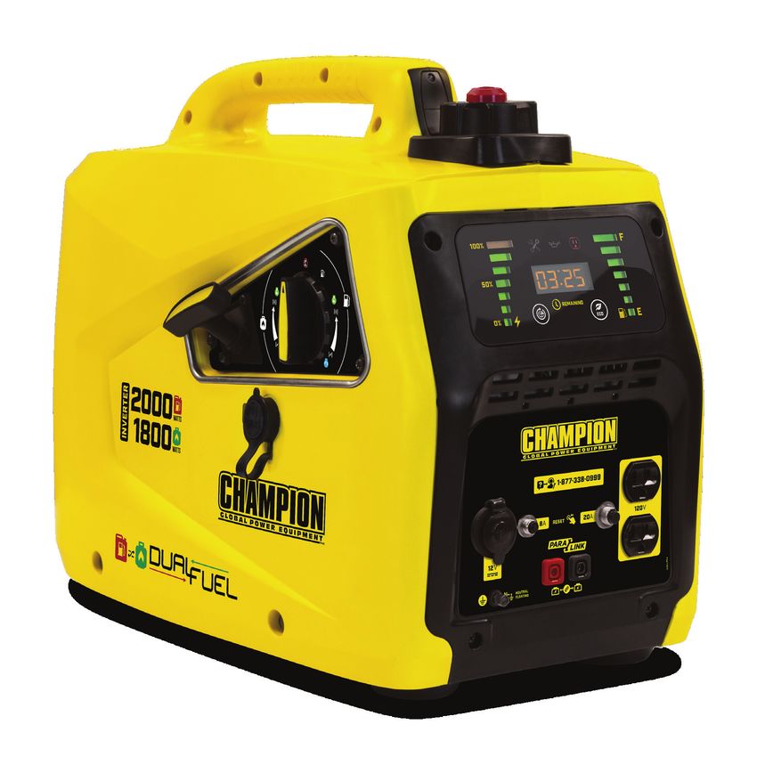
2000W Dual Fuel Inverter Generator
Patent Pending
REGISTER YOUR PRODUCT ONLINE
at championpowerequipment.com
or visit championpowerequipment.com
READ AND SAVE THIS MANUAL. This manual contains important safety precautions which should be read and understood before operating the product.
Failure to do so could result in serious injury. This manual should remain with the product.
Specifications, descriptions and illustrations in this manual are as accurate as known at the time of publication, but are subject to change without notice.
This product is rated in accordance with PGMA (Portable Generator Manufacturers’ Association) standard PGMA G300 (Standard for Testing and Validating
Performance of Portable Generators).
Made in China - REV 20190524 Champion Power Equipment, Inc., Santa Fe Springs, CA USA100402 - 2000W Dual Fuel Inverter Generator Table of Contents
TABLE OF CONTENTS Maintenance.............................................. 22
Cleaning the Generator......................................... 23
Introduction................................................. 3 Changing the Engine Oil........................................ 23
Safety Definitions........................................ 3 Cleaning and Adjusting the Spark Plug(s)................. ..... 23
Cleaning the Air Filter...................................... ..... 24
Important Safety Instructions..................... 4
Cleaning the Spark Arrestor............................... ..... 24
Fuel Safety....................................................... 6
Replacing Fuel Light Batteries.................................. 24
Safety Symbols................................................... 7
Adjusting the Governor..................................... ..... 25
Operation Symbols............................................... 8
Maintenance Schedule.......................................... 25
Quickstart Label Symbols....................................... 9
Safety Labels.................................................... 10 Storage...................................................... 26
Short Term Storage (up to 1 year).............................. 26
Controls and Features................................ 11
Long Term Storage (more than 1 year)......................... 26
Generator........................................................ 11
Removing from Storage......................................... 27
Power Panel..................................................... 12
Outlet Panel..................................................... 13 Specifications............................................ 28
FCC Statement.................................................. 14 Generator Specifications........................................ 28
Engine Specifications........................................... 28
Assembly.................................................... 15
Oil Specifications................................................ 28
Unpacking....................................................... 15
Fuel Specifications.............................................. 28
Add Engine Oil................................................... 15
Spark Plug Specifications....................................... 28
Add Fuel: Gasoline.............................................. 16
Valve Specifications............................................. 28
Add Fuel: Propane (LPG)........................................ 17
Temperature Specifications................................ ..... 28
Grounding....................................................... 17
Parts Diagram...................................................29
Operation.................................................... 18 Parts List........................................................30
Generator Location.............................................. 18 Engine Parts Diagram...................................... ..... 32
Grounding....................................................... 18 Engine Parts List........................................... .....33
Surge Protection................................................ 18 Wiring Diagram..................................................35
Starting the Engine: Gasoline................................... 18
Starting the Engine: Propane (LPG)............................ 19
Troubleshooting...................................... ... 36
Connecting Electrical Loads.................................... 20 Warranty*.................................................. 37
Do Not Overload Generator..................................... 20 Warranty Qualifications......................................... 37
Eco (Economy) Mode............................................ 21 Repair/Replacement Warranty............................. ..... 37
12V DC Automotive Style Outlet................................ 21 Do Not Return The Unit To The Place Of Purchase............ 37
Parallel Operation............................................... 22 Warranty Exclusions............................................ 37
Stopping the Engine............................................. 22 Other Exclusions................................................ 37
Limits of Implied Warranty and Consequential Damage.. ..... 37
Contact Information............................................. 37
2100402 - 2000W Dual Fuel Inverter Generator Introduction
INTRODUCTION SAFETY DEFINITIONS
Congratulations on your purchase of a Champion Power The purpose of safety symbols is to attract your attention to
Equipment (CPE) product. CPE designs, builds, and supports possible dangers. The safety symbols, and their explanations,
all of our products to strict specifications and guidelines. With deserve your careful attention and understanding. The safety
proper product knowledge, safe use, and regular maintenance, warnings do not by themselves eliminate any danger. The
this product should bring years of satisfying service. instructions or warnings they give are not substitutes for proper
accident prevention measures.
Every effort has been made to ensure the accuracy and
completeness of the information in this manual at the time
of publication, and we reserve the right to change, alter and/ DANGER
or improve the product and this document at any time without DANGER indicates a hazardous situation which,if not
prior notice. avoided, will result in death or serious injury.
Since CPE highly values how our products are designed,
manufactured, operated and are serviced, and also highly
WARNING
value your safety and the safety of others, we would like you to
take the time to review this product manual and other product WARNING indicates a hazardous situation which, if not
materials thoroughly and be fully aware and knowledgeable avoided, could result in death or serious injury.
of the assembly, operation, dangers and maintenance of the
product before use. Fully familiarize yourself, and make sure
others who plan on operating the product fully familiarize CAUTION
themselves too, with the proper safety and operation CAUTION indicates a hazardous situation which, if not
procedures before each use. Please always exercise common avoided, could result in minor or moderate injury.
sense and always err on the side of caution when operating
the product to ensure no accident, property damage, or injury
occurs. We want you to continue to use and be satisfied with NOTICE
your CPE product for years to come.
NOTICE is used to address practices not related to physical
When contacting CPE about parts and/or service, you will injury.
need to supply the complete model and serial numbers of your
product. Transcribe the information found on your product’s
nameplate label to the table below
CPE TECHNICAL SUPPORT TEAM
1-877-338-0999
MODEL NUMBER
100402
SERIAL NUMBER
DATE OF PURCHASE
PURCHASE LOCATION
3100402 - 2000W Dual Fuel Inverter Generator Important Safety Instructions
IMPORTANT SAFETY INSTRUCTIONS DANGER
WARNING Rotating parts can entangle hands, feet, hair, clothing and/
or accessories. Traumatic amputation or severe laceration
Cancer and Reproductive Harm – www.P65Warnings. can result.
ca.gov
Keep hands and feet away from rotating parts.
Tie up long hair and remove jewelry.
DANGER
Operate equipment with guards in place.
Generator exhaust contains carbon monoxide, a colorless,
odorless, poison gas. Breathing carbon monoxide will cause DO NOT wear loose-fitting clothing, dangling drawstrings or
nausea, dizziness, fainting or death. If you start to feel dizzy items that could become caught.
or weak, get to fresh air immediately.
OPERATE GENERATOR OUTDOORS ONLY IN A WELL WARNING
VENTILATED AREA. Operation of this equipment may create sparks that can
DO NOT operate the generator inside any building, including start fires around dry vegetation.
garages, basements, crawlspaces and sheds, enclosure or
A spark arrestor may be required. The operator should
compartment, including the generator compartment of a
contact local fire agencies for laws or regulations relating to
recreational vehicle.
fire prevention requirements.
DO NOT allow exhaust fumes to enter a confined area
through windows, doors, vents or other openings.
DANGER
DANGER Generator produces powerful voltage.
Using a generator indoors CAN KILL YOU IN MINUTES. DO NOT touch bare wires or receptacles.
Generator exhaust contains carbon monoxide. This is a DO NOT use electrical cords that are worn, damaged or
poison you cannot see or smell. frayed. Use Champion electrical cords only for proper
application.
NEVER use inside a home or garage, EVEN IF doors and
windows are open. DO NOT operate generator in wet weather.
ONLY use OUTSIDE and far away from windows, doors, DO NOT allow children or unqualified persons to operate or
and vents. service the generator
Use a ground fault circuit interrupter (GFCI) in damp areas
and areas containing conductive material such as metal
decking.
Connection to your home’s electrical system requires a
listed 30A transfer switch installed by a licensed electrician
and approved by the local authority having jurisdiction. The
Install battery-operated carbon monoxide alarms or plug-in connection must isolate the generator from the utility power
carbon monoxide alarms with battery back-up according to and must comply with all applicable laws and electrical
the manufacturer’s instructions. codes.
WARNING
Sparks can result in fire or electrical shock.
When servicing the generator:
Disconnect the spark plug wire and place it where it cannot
contact the plug or any other metal object.
DO NOT check for spark with the plug removed.
Use only approved spark plug testers.
4100402 - 2000W Dual Fuel Inverter Generator Important Safety Instructions
WARNING CAUTION
Running engines produce heat. Severe burns can occur on Improper treatment or use of the generator can damage it,
contact. Combustible material can catch fire on contact. shorten its life and void your warranty.
DO NOT touch hot surfaces. Use the generator only for intended uses.
Avoid contact with hot exhaust gases. Operate only on level surfaces.
Allow equipment to cool before touching. DO NOT expose generator to excessive moisture, dust,
or dirt.
Maintain at least 3 ft. (91.4 cm) of clearance on all sides to
ensure adequate cooling. DO NOT allow any material to block the cooling slots.
Maintain at least 5 ft. (1.5 m) of clearance from combustible If connected devices overheat, turn them off and disconnect
materials. them from the generator.
DO NOT use the generator if:
WARNING –– Electrical output is lost
Rapid retraction of the starter cord will pull hand and arm –– Equipment sparks, smokes or emits flames
towards the engine faster than you can let go. Unintentional –– Equipment vibrates excessively
startup can result in entanglement, traumatic amputation or
laceration. Broken bones, fractures, bruises or sprains could
result. WARNING
When starting engine, pull the starter cord slowly until Medical and life support uses.
resistance is felt and then pull rapidly to avoid kickback.
In case of emergency, call 911 immediately.
DO NOT start or stop the engine with electrical devices
NEVER use this product to power life support devices or life
plugged in and turned on.
support appliances.
NEVER use this product to power medical devices or
CAUTION medical appliances.
Exceeding the generator’s running capacity can damage the Inform your electricity provider immediately if you or anyone
generator and/or electrical devices connected to it. in your household depends on electrical equipment to live.
DO NOT overload the generator. Inform your electrical provider immediately if a loss of power
would cause you or anyone in your household to experience
DO NOT tamper with the governed speed.
a medical emergency.
DO NOT modify the generator in any way.
CAUTION
Start the generator and allow the engine to stabilize before
connecting electrical loads.
Connect electrical equipment in the off position, and then
turn them on for operation.
Turn electrical equipment off and disconnect before
stopping the generator.
5100402 - 2000W Dual Fuel Inverter Generator Important Safety Instructions
Fuel Safety DO NOT pump gasoline directly into the generator at the gas
station. Use an approved container to transfer the fuel to the
DANGER generator.
DO NOT overfill the gasoline tank.
GASOLINE, GASOLINE VAPORS AND PROPANE (LPG) ARE
HIGHLY FLAMMABLE AND EXPLOSIVE. Always keep gasoline away from sparks, open flames, pilot
lights, heat and other sources of ignition.
Fire or explosion can cause severe burns or death.
DO NOT light or smoke cigarettes.
Gasoline and gasoline vapors: When starting the generator:
–– Gasoline is highly flammable and explosive. DO NOT attempt to start a damaged generator.
–– Gasoline can cause a fire or explosion if ignited. Make certain that the gasoline cap, air filter, spark plug, fuel
lines and exhaust system are properly in place.
–– Gasoline is a liquid fuel but it’s vapors can ignite.
Allow spilled gasoline to evaporate fully before attempting to
–– Gasoline is a skin irritant and needs to be cleaned up
start the engine.
immediately if spilled on skin or clothes.
Make certain that the generator is resting firmly on level
–– Gasoline has a distinctive odor, this will help detect potential
ground.
leaks quickly.
When operating the generator:
–– In any petroleum gas fire, flames should not be extinguished
unless by doing so the fuel supply valve can be turned OFF. DO NOT move or tip the generator during operation.
This is because if a fire is extinguished and a supply of DO NOT tip the generator or allow fuel or oil to spill.
fuel is not turned OFF, then an explosion hazard could be
created. When transporting or servicing the generator:
–– Gasoline expands or contracts with ambient temperatures. Make certain that the fuel valve is in the OFF position and the
Never fill the gasoline tank to full capacity, as gasoline gasoline tank is empty.
needs room to expand if temperatures rise. For LPG compatible models, be sure that the LPG cylinder is
LPG: disconnected and stored securely away from the generator.
–– LPG is highly flammable and explosive. Disconnect the spark plug wire.
–– LPG is under pressure and can cause a fire or explosion if When storing the generator:
ignited. Store away from sparks, open flames, pilot lights, heat and
–– LPG is heavier than air and can settle in low places while other sources of ignition.
dissipating. Do not store generator, gasoline or LPG cylinders near furnaces,
–– LPG has a distinctive odor added to help detect potential water heaters, or any other appliances that produce heat or
leaks quickly. have automatic ignitions.
–– In any petroleum gas fire, flames should not be extinguished WARNING
unless the fuel supply valve is turned OFF. This is because if
a fire is extinguished and a supply of fuel is not turned OFF, Never use a gasoline container, gasoline tank, LPG
then an explosion hazard could be created. connector hose, LPG cylinder or any other fuel item that is
damaged or appears damaged.
–– When exchanging LPG cylinders, be sure the cylinder valve
is of the same type.
–– Always keep the LPG cylinder in an upright position.
–– LPG will burn skin if it comes in contact with it. Keep any
and all LPG away from skin at all times.
When adding or removing gasoline:
Turn the generator off and let it cool for at least two minutes
before removing the gasoline cap. Loosen the cap slowly to
relieve pressure in the tank.
Only fill or drain gasoline outdoors in a well-ventilated area.
6100402 - 2000W Dual Fuel Inverter Generator Important Safety Instructions
Safety Symbols
Some of the following symbols may be used on this product. Please study them and learn their meaning. Proper interpretation of
these symbols will allow you to more safely operate the product.
SYMBOL MEANING
Read Operator’s Manual. To reduce the risk of injury, user must read and understand operator’s
manual before using this product.
Clearance. Keep all objects at least 5 feet from this machine. Heat from the muffler and exhaust
gas can ignite combustible objects.
Ground. Consult with local electrician to determine grounding requirements before operation.
Electric Shock. Failure to use in dry conditions and to observe safe practices can result in electric
shock. Improper connections to a building can allow current to backfeed into utility lines, creating an
electrocution hazard. A transfer switch must be used when connecting to a building.
Fire/Explosion. Fuel and its vapors are extremely flammable and explosive. Fire or explosion can
cause severe burns or death. Operation of this equipment may create sparks that can start fires
around dry vegetation. A spark arrestor may be required. The operator should contact local fire
agencies for laws or regulations relating to fire prevention requirements.
Hot Surface. To reduce the risk of injury or damage, avoid contact with any hot surface.
Open Flame Alert. Fuel and its vapors are extremely flammable and explosive. Keep fuel away from
smoking, open flames, sparks, pilot lights, heat, and other ignition sources.
Wet Conditions Alert. Do not expose to rain or use in damp locations.
7100402 - 2000W Dual Fuel Inverter Generator Important Safety Instructions
Operation Symbols
Some of the following symbols may be used on this product. Please study them and learn their meaning. Proper interpretation of
these symbols will allow you to more safely operate the product.
SYMBOL MEANING SYMBOL MEANING
Engine START Maintenance Required Indicator
Engine RUN Low Oil Level Indicator
Engine STOP Receptacle Status
STOP or OFF Circuit Breaker Reset: Push
Run out of fuel. Stopping the
Ground Terminal
generator.
Neutral Floating. Neutral circuit IS
Gasoline fuel selection / Fuel Level NOT electrically connected to the
frame/ground of the generator.
Propane fuel selection / Propane
Parallel Connection(s)
fuel port
Power Output. Percentage of
available power from generator being
used.
Remaining Fuel Time
Overload Reset Switch
Economy Mode Switch
ECO
8100402 - 2000W Dual Fuel Inverter Generator Important Safety Instructions
Quickstart Label Symbols
Some of the following symbols may be used on this product. Please study them and learn their meaning. Proper interpretation of
these symbols will allow you to more safely operate the product.
1 2A 3A 4 5 6 7 1 2A 3
1663-L-OP-A
b
c +
2B
10W-30 2B 3B
+
LPN 1663-L-OP Colors
Starting the Engine Rev
Size
A
256 x 48 mm
Stopping the EngineK CG1 376 152 186 W
Artwork Notes Revision Changes
1. Turn off and unplug all connected electrical loads.
3mm corner radius; 2mm safe margin; white to be ---
printed shown in 50% process magenta
DANGER This artwork belongs to Champion Power Equipment. The contents are confidential and privileged and shall not be disclosed to or used by or for
outside parties without the explicit consent of Champion Power Equipment.
2. Fuel Valve
Move generator outside and far away from windows,
2a. If operating on gasoline, turn the fuel vent lever to the
doors and intake ventilation covers.
“OFF” position.
1. Check oil level. 2b. If operating on LPG, close the valve on the LPG tank.
Recommended oil is 10W-30. 3. Turn the EZ Start dial to the “STOP” position.
2. Add fuel.
2a. If operating on gasoline, check gasoline level.
When adding gasoline, use a minimum octane rating of
85 and an ethanol content of 10% or less by volume.
2b. If operating on propane, connect propane tank.
Open valve on propane tank.
3. Fuel Selector
3a. Turn EZ Start dial to the right for gasoline operation.
Then turn the fuel vent lever to the “ON” position.
3b. Turn EZ Start dial to the left for LPG operation.
4. Move EZ Start dial to “CHOKE” position.
5. Pull the recoil cord.
6. Move the EZ Start dial to “RUN” position.
7. Plug in desired device.
9100402 - 2000W Dual Fuel Inverter Generator Important Safety Instructions
Safety Labels
These labels warn you of potential hazards that can cause serious injury. Read them carefully.
If a label comes off or becomes hard to read, contact Technical Support Team for possible replacement.
C
A B
D
Top Muffler Side
LABEL DESCRIPTION
Using a generator indoors CAN KILL NEVER use inside ONLY use OUTSIDE
DANGER YOU IN MINUTES. Generator exhaust a home or garage, and far away from
contains carbon monoxide. This is a EVEN IF doors and windows, doors,
poison you cannot see or smell. windows are open. and vents.
El uso de un generador en interiores PUEDE MATARLO EN MINUTOS. El escape del generador contiene monóxido de carbono.
A PELIGRO Éste es un veneno que no se puede ver ni oler. NUNCA lo use dentro del hogar ni el garaje, INCLUSO SI las puertas y ventanas CO Danger
están abiertas. Úselo SÓLO a la INTEMPERIE lejos de ventanas, puertas, y orificios de ventilación.
Utiliser un générateur à l’intérieur PEUT VOUS TUER EN QUELQUES MINUTES. L’échappement du générateur contient du
DANGER monoxyde de carbone. Il s’agit d’un poison que vous ne pouvez ni voir ni sentir. Ne l’utilisez JAMAIS dans la maison ou le garage
1308-L-SF-B
MÊME SI les portes et les fenêtres sont ouvertes. Utilisez-le UNIQUEMENT À L’EXTÉRIEUR, loin des fenêtres, portes et trappes
de ventilation.
LPN 1308-L-SF Colors
Rev B
B Size 204x 46 mm K 485 --- --- ---
Safety Icons
Artwork Notes Revision Changes
3mm corner radius; 2mm safe margin; white to be B: Updated size match DF generator
printed shown in 50% process magenta
1161-L-SF-A
This artwork belongs to Champion Power Equipment. The contents are confidential and privileged and shall not be disclosed to or used by or for
outside parties without the explicit consent of Champion PowerLPN
Equipment.
1161-L-SF Colors
UNLEADED FUEL Rev A
ONLY. Minimum octane rating
of 85. Maximum 10% ethanol.
Size 121 x 40 mm K 485 2945 109 ---
C GASOLINA REGULAR SOLAMENTE. 85 octanos
Fuel
1032-L-OP-A
Artwork Notes Revision Changes
como mínimo. Máximo de etanol de 10%.
3mm corner radius; 2mm safe margin; white to be
printed shown in 50% process magenta
---
ESSENCE SANS PLOMB SEULEMENT. Indice
d’octane minimal de 85. Maximum 10 % d'éthanol.
This artwork belongs to Champion Power Equipment. The contents are confidential and privileged and shall not be disclosed to or used by or for
outside parties without the explicit consent of Champion Power Equipment.
DO NOT TOUCH! Exhaust gases, muffler
WARNING and engine components are extremely HOT
and cause burns.
Operation
LPN of1032-L-OP
this equipment may create sparks that can start fires
Colors
around dry vegetation. A spark arrestor may be required. The
operator should contact local fire agencies for laws and regulations
Rev to fire
relating A prevention requirements. If installed, clean every 100
hours or every season.
Size 78 x 20 mm K 109 --- --- ---
¡NO TOCAR! Los gases de escape, el silenciador y los compnonentes
ADVERTENCIA del motor están extremadamente CALIENTES y causan quemaduras.
D Artwork Notes
operador debe comunicarse
La operación de este equipo puede producir Revision Changes
chispas que pueden
provocar incendios alrededor de la vegetación seca. Un supresor de chispas puede que sea necesario. El Hot Surface
3mm corner radius; 2mm safe margin con las agencias locales de ---bomberos para las leyes y reglamentos relativos
a los requisitos de prevención de incendios. Si está instalado, limpie cada 100 horas o cada temporada.
NE PAS TOUCHER! Les gaz d’échappement, le silencieux et les
AVERTISSEMENT pièces du moteur sont extrêmement CHAUDS et peuvent causer
This artwork belongs to Champion Power Equipment. Thedes contents are confidential and privileged and shall not be disclosed to or used by or for
brûlures.
outside parties without Cet
the équipement
explicit consent
peut of Champion Power et
Equipment.
1310-L-SF-A
créer des étincelles provoquer un incendie dans la végétation sèche. Un
pare-étincelles peut être requis. L’opérateur doit communiquer avec le service d’incendie local pour
connaître les lois et les règlements en matière de prévention des incendies. Si elle est installée,
nettoyez toutes les 100 heures ou chaque saison.
LPN 1310-L-SF Colors
Rev A
Size 88 x 56 mm K 152 --- --- ---
Artwork Notes Revision Changes
3mm corner radius; 2mm safe margin; white to be ---
printed shown in 50% process magenta
This artwork belongs to Champion Power Equipment. The contents are confidential and privileged and shall not be disclosed to or used by or for
outside parties without the explicit consent of Champion Power Equipment.
10100402 - 2000W Dual Fuel Inverter Generator Controls and Features
CONTROLS AND FEATURES
Read this operator’s manual before operating your generator. Familiarize yourself with the location and function of the controls and
features. Save this manual for future reference.
Generator
9 8
1
7
10
6
2
11
5
3 4
1. Carrying Handle – Used to lift or carry the unit. 7. Fuel Cap – Remove to add fuel.
2. Recoil Starter – Used to manually start the engine. 8. Fuel Lever Vent – Turn this valve to the “ON” position to
supply air to the tank.
3. LPG Inlet – Used to connect LPG fuel source to generator.
9. Fuel Fill Assist LED – Push-button LED used to illuminate
4. EZ Start Dial – Used to start and stop the generator. When
the gasoline fill area
operating by propane, this switch will NOT stop the engine.
10. Maintenance Cover
5. Outlet Panel – See “Outlet Panel” section.
11. Muffler
6. Power Panel – See “Power Panel” section.
11100402 - 2000W Dual Fuel Inverter Generator Controls and Features
Power Panel
2 3 4
100% F
1 50%
00:00 5 8
REMAINING
0% ECO
E
6 7
1. Power Output – Percentage of available power from 5. LED Display
generator being used.
5a. Flashing Blue – Total run time (first 5 seconds after
2. Maintenance Indicator unit started).
2a. Off – No service required. 5b. Amber – Remaining fuel run time or “LPG” in LPG
2b. Yellow – Service required per Maintenance Schedule. mode.
3. Low Oil Level Indicator 6. AC Overload Reset Button – Used to re-energize
receptacles after overload fault and reset maintenance
3a. Off – Oil level OK. schedule.
3b. Yellow – Oil level low. Unit will shut down or not start 6a. OFF – Systems normal.
until oil is at required level.
6b. Yellow – Maintenance required.
4. Receptacle Status
6c. Blinking Red – Overload fault.
4a. Green – All systems OK.
7. Economy Mode Switch – Enables/disables automatic idle
4b. Red – Nearing overload but receptacle still has power. control.
4c. Flashing Red – Overload fault and receptacle has no 7a. OFF – Economy mode OFF.
power.
7b. Green – Economy mode ON.
8. Fuel Level Indicator – Amount of fuel remaining.
12100402 - 2000W Dual Fuel Inverter Generator Controls and Features
Outlet Panel
B
A
2
3
1
1. Ground Terminal – Consult an electrician for local
RECEPTACLES
grounding regulations.
12V DC, 8 Amp (Automotive)
2. Circuit Breakers (Push Reset) – Protects the generator
z
May be used to supply electrical power for
against electrical overloads. A
operation of 12 Volt DC, 8 Amp electrical
3. Parallel Outlets – Used for parallel operation (parallel kit loads.
sold separately). (2×) 120V AC, 20A (NEMA 5-20R)
A
May be used to supply electrical power for
B
operation of 120 Volt AC, 20 Amp, single
phase, 60 Hz electrical loads.
*Warning: Do not operate a device while it is plugged into the 12V DC outlet.
Prolonged exposure to engine exhaust can cause serious injury or death. While
charging a device do no place on the exhaust side of the generator. Extreme
heat caused by exhaust can damage the device, and cause a potential fire
hazard.
13100402 - 2000W Dual Fuel Inverter Generator Controls and Features
FCC Statement Parts Included
1. This device complies with Part 15 of the FCC Rules. Accessories
Operation is subject to the following two conditions: Oil Funnel............................................................................... 1
1a. This device may not cause harmful interference. 2.3 ft. (0.7 m) LPG Hose with Regulator.................................. 1
1b. This device must accept any interference received, Dual 2.4A Port USB Adapter................................................... 1
including interference that may cause undesired
operation.
2. Changes or modifications not expressly approved by the
party responsible for compliance could void the user’s
authority to operate the equipment.
NOTICE
This equipment has been tested and found to comply with
the limits for a Class B digital device, pursuant to Part 15
of the FCC Rules. These limits are designed to provide
reasonable protection against harmful interference in a
residential installation. This equipment generates uses and
can radiate radio frequency energy and, if not installed
and used in accordance with the instructions, may cause
harmful interference to radio communications. However,
there is no guarantee that interference will not occur in a
particular installation. If this equipment does cause harmful
interference to radio or television reception, which can be
determined by turning the equipment off and on, the user is
encouraged to try to correct the interference by one or more
of the following measures:
–– Reorient or relocate the receiving antenna.
–– Increase the separation between the equipment and
receiver.
–– Connect the equipment into an outlet on a circuit
different from that to which the receiver is connected.
Consult dealer or an experienced radio/TV technician for help.
14100402 - 2000W Dual Fuel Inverter Generator Assembly
ASSEMBLY
This unit ships from our factory without oil. It must be properly
serviced with fuel and oil before operation.
If you have any questions regarding the assembly of your
generator, call our Technical Support Team at 1-877-338-0999.
Please have your serial number and model number available.
Unpacking
1. Set the shipping carton on a solid, flat surface.
2. Remove everything from the carton except the generator.
3. Using the carrying handles of the unit, carefully remove
the generator from the box (two people lifting is
recommended). 3. Remove oil fill cap/dipstick to add oil.
4. Using a funnel, add up to 0.4 qt. (0.4 L) of oil (not included)
Add Engine Oil and replace oil fill cap/dipstick. DO NOT OVERFILL.
5. Check engine oil level daily and add as needed.
CAUTION
DO NOT attempt to crank or start the engine before it has
been properly filled with the recommended type and amount
of oil. Damage to the generator as a result of failure to MAX
follow these instructions will void your warranty. OIL DIP STICK
MIN
NOTICE
The generator rotor has a sealed, pre-lubricated ball bearing
that requires no additional lubrication for the life of the bearing. NOTICE
Once oil has been added, a visual check should show oil
NOTICE about 1-2 threads from running out of the fill hole.
The recommended oil type is 10W-30 automotive oil. If using the dipstick to check oil level, DO NOT screw in the
dipstick while checking.
Recommended Engine Oil Type
10W-30 NOTICE
5W-30 10W-40 Check oil often during the break-in period. Refer to the
Maintenance section for recommended service intervals.
5W-30 Synthetic
°F -20 0 20 40 60 80 100 120
°C -28.9 -17.8 -6.7 4.4 15.6 26.7 37.8 48.9 CAUTION
Ambient temperature
The engine is equipped with a low oil shut-off and will stop
when the oil level in the crankcase falls below the threshold
1. Place the generator on a flat, level surface. level.
2. Remove the maintenance cover.
15100402 - 2000W Dual Fuel Inverter Generator Assembly
NOTICE CAUTION
The first 5 hours of run time are the break-in period for the Use regular unleaded gasoline with a minimum octane
unit. During the break in period stay at or below 50% of the rating of 85 and an ethanol content of 10% or less by
running watt rating and vary the load occasionally to allow volume.
stator windings to heat and cool. Adjusting the load will also
cause engine speed to vary and help seat piston rings. After DO NOT mix oil and gasoline.
the 5 hour break-in period, change the oil. Fill tank to approximately ¼ in. (6.4 mm) below the top of
the tank to allow for gasoline expansion.
NOTICE DO NOT pump gasoline directly into the generator at the
pump. Use an approved container to transfer the gasoline to
Weather will affect engine oil and engine performance. the generator.
Change the type of engine oil used based on weather
DO NOT fill tank indoors.
conditions to suit the engine needs.
DO NOT fill tank when the engine is running or hot.
NOTICE DO NOT overfill the tank.
DO NOT light cigarettes or smoke when filling the tank.
Synthetic oil may be used after the 5 hour initial break-
in period. Using synthetic oil does not increase the
recommended oil change interval. Full synthetic 5W-30 oil WARNING
will aid in starting in cold ambient100402 - 2000W Dual Fuel Inverter Generator Assembly
Add Fuel: Propane (LPG) CAUTION
1. Confirm the EZ Start dial is in the OFF position.
Do not allow children to tamper or play with the LPG cylinder
2. If using a new propane cylinder, remove the plastic cap or hose connections.
from the cylinder valve.
3. Attach the LPG hose assembly (included) to the propane
CAUTION
cylinder valve and hand tighten.
Use approved LPG cylinders equipped with an OPD
4. Remove the rubber boot covering the propane connection
(overfilling prevention device) valve. Always keep the
port on the inverter.
cylinder in a vertical position with the valve on top and
5. Align the plastic finger on the male hose fitting on the installed at ground level on a flat surface. Cylinders must
LPG hose assembly with the slot below the female quick not be installed near any heat source and should not be
connect coupling on the inverter. exposed to sun, rain, and dust. When transporting and
6. Insert the hose fitting into the quick connect coupling and storing, turn off the cylinder valve and generator LPG valve,
push in until you hear a “click” and the outside collar of the and disconnect the cylinder. Plug the outlet, usually by a
quick connect coupling moves forward. plastic protective cap, if one is available. Keep cylinders
away from heat and ventilated when in a vehicle.
WARNING
If there is a strong smell of LPG: Close valve on the cylinder.
Check all connections for leaks by wetting the fittings
with a solution of soap and water. Bubbles which appear
or bubbles which grow indicate that a leak exists. Do not
smoke or light a cigarette, or check for leaks using a match,
open flame source or lighter. Contact a qualified technician
to inspect and repair an LPG system if a leak is found,
before using the generator.
7. Check all connections for leaks by wetting the fittings with
a solution of soap and water. Bubbles which appear or Grounding
bubbles which grow indicate that a leak exists. If a leak
exists at a fitting then turn off the valve on the cylinder Your generator must be properly connected to an appropriate
and tighten the fitting. Turn the valve back on and recheck ground to help prevent electric shock.
the fitting with the soap and water solution. If the leak
continues or if the leak is not at a fitting then do not use WARNING
the generator and contact customer service. Failure to properly ground the generator can result in
electric shock.
NOTICE
–– The LPG hose included with this unit works with A ground terminal connected to the frame of the generator has
standard 20 and 30 pound LPG tanks. been provided (see Controls and Features for terminal location).
For remote grounding, connect of a length of heavy gauge
–– Verify the requalification date on the cylinder has not
(12 AWG minimum) copper wire between the generator ground
expired.
terminal and a copper rod driven into the ground. We strongly
–– All new cylinders must be purged of air and moisture recommend that you consult with a qualified electrician to
prior to filling. Used cylinders that have not been plugged ensure compliance with local electrical codes.
or kept closed must also be purged.
–– The purging process should be done by an LPG supplier.
(cylinders from an exchange supplier should have been
purged and filled properly already).
–– Always position the cylinder so the connection between
the cylinder valve and generator inlet won’t cause sharp
bends or kinks in the LPG hose.
17100402 - 2000W Dual Fuel Inverter Generator Operation
OPERATION Grounding
A ground terminal connected to the frame of the generator has
Generator Location been provided (see Controls and Features for terminal location).
NEVER operate the generator inside any building, including Neutral Floating*
garages, basements, crawlspaces and sheds, enclosure or –– Neutral circuit IS NOT electrically connected to the frame/
compartment, including the generator compartment of a ground of the generator.
recreational vehicle. Please consult your local authority. In
–– The generator (stator winding) is isolated from the frame
some areas, generators must be registered with the local
and from the AC receptacle ground pin.
utility. Generators used at construction sites may be subject
to additional rules and regulations. Generators should be on –– Electrical devices that require a grounded receptacle pin
a flat, level surface at all times. (Even while not in operation) connection will not function if the receptacle ground pin is
Generators must have at least 5 ft. (1.5 m) of clearance from not functional.
all combustible material. In addition to clearance from all Neutral Bonded to Frame*
combustible material, generators must also have at least 3 ft.
(91.4 cm) of clearance on all sides to allow for adequate cooling, –– Neutral circuit IS electrically connected to the frame/ground
maintenance and servicing. Generators should never be started of the generator.
or operated in the back of a SUV, camper, trailer, in the bed of –– The generator system ground connects lower frame
a truck (regular, flat or otherwise), under staircases/stairwells, cross-member below the alternator. The system ground is
next to walls or buildings, or in any other location that will not connected to the AC neutral wire.
allow for adequate cooling of the generator and/or the muffler. * See your model's control panel for specified type of grounding.
DO NOT contain generators during operation. Allow generators
to properly cool before transport or storage.
Surge Protection
Install battery-operated carbon monoxide alarms or plug-in
carbon monoxide alarms with battery back-up in your home Electronic devices, including computers and many
according to the manufacturer’s instructions. programmable appliances use components that are designed
to operate within a narrow voltage range and may be affected
Place the generator in a well-ventilated area. DO NOT place the by momentary voltage fluctuations. While there is no way to
generator near vents or intakes where exhaust fumes could prevent voltage fluctuations, you can take steps to protect
be drawn into occupied or confined spaces. Carefully consider sensitive electronic equipment.
wind and air currents when positioning generator.
–– Install UL1449, CSA-listed, plug-in surge suppressors on the
Failure to follow proper safety precautions may void outlets feeding your sensitive equipment.
manufacturer’s warranty. Surge suppressors come in single- or multi-outlet styles.
They’re designed to protect against virtually all short-
WARNING duration voltage fluctuations.
Do not operate or store the generator in rain, snow, or wet
weather. Starting the Engine: Gasoline
Using a generator or electrical appliance in wet conditions, 1. Make certain the generator is on a flat, level surface.
such as rain or snow, or near a pool or sprinkler system, 2. Disconnect all electrical loads from the generator. Never
or when your hands are wet, could result in electrocution. start or stop the generator with electrical devices plugged
in or turned on.
WARNING 3. Turn the fuel cap vent lever to the “ON” position.
During operation the muffler and exhaust fumes produced
will become hot. If adequate cooling and breathing space
are not supplied, or if the generator is blocked or contained,
temperatures can become extremely heated and may lead
to fire.
18100402 - 2000W Dual Fuel Inverter Generator Operation
4. Turn EZ Start dial clockwise to the full CHOKE position.
NOTICE
For gas starting in cold ambient 30°C (86°F): Rotate the EZ Start dial to 75% of the
full choke position for only one pull of the recoil starter. If
generator does not start after first pull, rotate the dial to the
RUN position for the next three pulls. Too much choke leads
do spark plug fouling and engine flooding. This will cause
the engine not to start.
19100402 - 2000W Dual Fuel Inverter Generator Operation
6. Move the EZ Start dial to the “RUN” position. Connecting Electrical Loads
Let the engine stabilize and warm up for a few minutes after
starting.
Plug in and turn on the desired 120 or 240 (if applicable) Volt AC
- -
single phase, 60 Hz electrical loads.
–– DO NOT connect 3-phase loads to the generator.
+ +
–– DO NOT connect 50 Hz loads to the generator.
–– DO NOT overload the generator.
7. Pull the starter cord slowly until resistance is felt and then WARNING
pull rapidly.
Connecting a generator to your electric utility company’s
NOTICE power lines or to another power source may be against
the law. In addition this action, if done incorrectly, could
Accumulation of frost on LPG cylinder and regulators is damage your generator and appliances and could cause
common during operation and normally is not an indication serious injury or even death to you or a utility worker who
of a problem. As LPG vaporizes and travels from the cylinder may be working on nearby power lines. If you plan to run a
to the generator engine it expands. The amount of frost portable electric generator during an outage, please notify
that forms can be affected by the size of the cylinder, the your electric utility company immediately and remember to
amount of LPG being used, the humidity of the air and other plug your appliances directly into the generator. Do not plug
operating conditions. the generator into any electric outlet in your home. Doing
In unusual situations this frost may eventually restrict so could create a connection to the utility company power
the flow of LPG to the generator resulting in deteriorating lines. You are responsible for ensuring that your generator’s
performance. For example, if the cylinder temperature is electricity does not feed back into the electric utility power
reduced to a very low level then the rate at which the LPG lines.
vaporizes is also reduced and may not provide sufficient If the generator will be connected to a building electrical
flow to the engine. This is not an indication of a problem system, consult your local utility company or a qualified
with the generator but only a problem with the flow of LPG electrician. Connections must isolate generator power from
from the cylinder. If generator performance seems to be utility power and must comply with all applicable laws and
deteriorating at the same time that ice formation is observed codes.
on tank valve, hose or regulator then some actions may be
taken to eliminate this symptom.
In these rare situations it can be helpful to reduce or Do Not Overload Generator
eliminate the cold fuel system effects by doing one of the Capacity
following:
Follow these simple steps to calculate the running and starting
–– Exchanging fuel cylinders to allow the first cylinder to watts necessary for your purposes:
warm up, repeating as necessary.
1. Select the electrical devices you plan on running at the
–– Placing the cylinder at the end of the generator near same time.
the handle, where engine fan air flows out from the
generator. This air is slightly heated by flowing over the 2. Total the running watts of these items. This is the amount
engine. The cylinder should not be placed in the path of of power you need to keep your items running.
the muffler outlet. 3. Identify the highest starting wattage of all devices
–– The cylinder can be temporarily warmed by pouring identified in step 1. Add this number to the number
warm water over the top of the cylinder. calculated in step 2. Starting wattage is the extra burst
of power needed to start some electric driven equipment.
Following the steps listed under “Power Management” will
guarantee that only one device will be starting at a time.
20100402 - 2000W Dual Fuel Inverter Generator Operation
Power Management 12V DC Automotive Style Outlet
Use the following formula to convert voltage and amperage to The 12V DC outlet(s) can be used with the supplied accessories
watts: and other commercially available 12V DC automotive style
Volts × Amps = Watts plugs. The DC output is unregulated and can damage some
products. Confirm the input voltage range of your item is at
To prolong the life of your generator and attached devices,
least 12-24V DC. When using the DC outlet turn the Eco Mode
follow these steps to add electrical load:
switch to the “OFF” position.
1. Start the generator with no electrical load attached
2. Allow the engine to run for several minutes to stabilize. WARNING
3. Plug in and turn on the first item. It is best to attach the Do not operate a device while it is plugged in to the 12V DC
item with the largest load first. outlet.
4. Allow the engine to stabilize. Prolonged exposure to engine exhaust can cause serious
5. Plug in and turn on the next item. injury or death.
6. Allow the engine to stabilize.
7. Repeat steps 5-6 for each additional item.
CAUTION
While charging a device do not place on the exhaust side of
NOTICE the generator. Extreme heat caused by exhaust can damage
the device, and cause a potential fire hazard.
Never exceed the specified capacity when adding loads to
the generator.
Battery Charging
1. Before connecting the battery charging cable (not included)
Eco (Economy) Mode to a battery that is installed in a vehicle, disconnect the
vehicle battery ground cable from the negative (–) battery
The Eco Mode switch can be activated to turn on economy
terminal.
control in order to minimize fuel consumption and noise while
operating the unit during times of reduced electrical output. Eco 2. Plug the battery charging cable into the 12V DC receptacle
Mode allows the engine speed to idle during periods of non-use. of the generator.
The engine speed returns to normal when an electrical load is 3. Connect the red (+) battery charger lead to the red (+)
connected. When the economy switch is off, the engine runs at battery terminal.
normal speed continuously. 4. Connect the black (–) battery charger lead to the black (–)
battery terminal.
5. Start the generator.
Important: The 12V DC output is unregulated and may damage
other 12V DC products. When using the 12V DC outlet, turn the
Economy mode switch to the “OFF” position.
CAUTION
Do not start the vehicle while the battery charging cable is
connected and the generator is running. It will not give the
battery a boost of power. The vehicle or the generator may
be damaged. Charge only vented wet lead acid batteries.
CAUTION
Other types of batteries may burst, causing personal injury
For periods of high electrical load or momentary or damage.
fluctuations, the Eco Mode should be off.
NOTICE
Be sure all electric devices including the lines and plug
connections are in good condition before connection to the
generator.
21100402 - 2000W Dual Fuel Inverter Generator Maintenance
Parallel Operation
The Champion model 100402 is parallel ready and can be
operated in parallel with another Champion unit to increase
the total available electrical power. A Champion model
100468 parallel kit (optional equipment) is required for parallel - -
operation. For a list of compatible models or to order a parallel
kit, please call customer service at 1-877-338-0999 or visit + +
www.championpowerequipment.com.
Detailed instructions for parallel kit installation and operation
of the connected generators are provided in the parallel kit
owner’s manual. NOTICE
If the generator will not be used for a period of two (2) weeks
Stopping the Engine or longer, please see the Storage section for proper engine
Gasoline and fuel storage.
1. Turn off and unplug all electrical loads. Never start or stop
the generator with electrical devices plugged in or turned
on. MAINTENANCE
2. Let the generator run at no-load for several minutes to Make certain that the generator is kept clean and stored
stabilize internal temperatures of the engine and generator. properly. Only operate the unit on a flat, level surface in a clean,
3. Turn the EZ Start dial counterclockwise to the STOP dry operating environment. DO NOT expose the unit to extreme
position. conditions, excessive dust, dirt, moisture or corrosive vapors.
NOTICE
When the Maintenance Indicator light is yellow, service is
required per the Maintenance Schedule Section. To reset
the Maintenance Indicator Light, hold down the AC Overload
- -
Reset Button for 3 seconds. (See Power Panel section under
+ +
Controls and Features.)
WARNING
Never operate a damaged or defective generator.
Important: Always ensure that the EZ Start dial and fuel vent
on the fuel cap are in the “OFF” position when the generator is
not in use. WARNING
Propane Improper maintenance will void your warranty.
1. Turn off and unplug all electrical loads. Never start or stop
the generator with electrical devices plugged in or turned NOTICE
on.
Maintenance, replacement, or repair of emission control
2. Let the generator run at no-load for several minutes to
devices and systems may be performed by any non-road
stabilize internal temperatures of the engine and generator.
engine repair establishment or individual.
3. Close the fuel valve on the propane cylinder.
4. Turn the EZ Start dial clockwise to the STOP position. The owner/operator is responsible for all periodic maintenance.
Complete all scheduled maintenance in a timely manner.
Correct any issue before operating the generator.
For service or parts assistance, contact our
Technical Support Team at 1-877-338-0999.
22100402 - 2000W Dual Fuel Inverter Generator Maintenance
Cleaning the Generator NOTICE
CAUTION Once oil has been added, a visual check should show oil
about 1-2 threads from running out of the fill hole. If using
DO NOT spray engine with water. the dipstick to check oil level, DO NOT screw in the dipstick
Water can enter the generator through the cooling slots and while checking.
damage the generator windings. It can also contaminate the
fuel system.
Cleaning and Adjusting the Spark Plug(s)
1. Use a damp cloth to clean exterior surfaces of the 1. Remove the maintenance cover.
generator.
2. Use a soft bristle brush to remove dirt and oil.
3. Use an air compressor (25 PSI) to clear dirt and debris
from the generator.
4. Inspect all air vents and cooling slots to ensure that they
are clean and unobstructed.
To prevent accidental starting, remove the spark plug wire
before performing any service. Make sure spark plug wire end
does not rest on any metal parts.
2. Remove the spark plug wire from the spark plug.
Changing the Engine Oil
3. Use a spark plug socket tool (not included), or a
Change oil when the engine is warm. Refer to the oil 13/16 in. (21 mm) socket (not included) to remove the plug.
specification to select the proper grade for your operating
environment. 4. Inspect the electrode on the plug. It must be clean and not
worn to produce the spark required for ignition.
1. Set the generator on top of a work bench or table.
5. Make certain the spark plug gap is
2. Remove the maintenance cover. 0.024-0.028 in. (0.6-0.7 mm).
3. Remove the oil filler cap.
4. Tilt the generator on its side and allow the oil to drain
completely. SPARK PLUG GAP
5. Add oil according to “Add Engine Oil” on Assembly
section. DO NOT OVERFILL. Oil not included for routine
maintenance.
6. Refer to the spark plug types in Specifications when
replacing the plug.
MAX 7. Firmly re-install the plug.
MIN OIL DIP STICK 8. Attach the spark plug wire to the spark plug.
9. Reinstall the maintenance cover.
6. Reinstall the maintenance cover.
7. Dispose of used oil at an approved waste management
facility.
23100402 - 2000W Dual Fuel Inverter Generator Maintenance
Cleaning the Air Filter
6. Replace the spark arrestor if it is damaged.
7. Position the spark arrestor on the muffler and attach by
reversing the steps from above.
1. Remove the maintenance cover.
2. Locate the air filter plastic cover. Remove the screw using CAUTION
a Phillips head screwdriver.
Failure to clean the spark arrestor will result in degraded
3. Remove the foam element. engine performance.
4. Wash in liquid detergent and water. Squeeze thoroughly dry
in a clean cloth. NOTICE
5. Saturate in clean engine oil.
Federal and local laws and administrative requirements
6. Squeeze in a clean, absorbent cloth to remove all excess indicate when and where spark arrestors are required.
oil. When ordered, spark arrestors are required for operation
7. Place the filter in the assembly. of this generator in National Forest lands. In California,
this generator must not be used on any forest-covered
8. Reattach the air filter cover. land, brush-covered land, or grass-covered land unless the
9. Reinstall the maintenance cover and tighten the cover engine is equipped with a spark arrestor.
screw securely.
Cleaning the Spark Arrestor Replacing Fuel Light Batteries
1. Allow the engine to cool completely before servicing the 1. Use a small screwdriver to disassemble the upper cover.
spark arrestor.
2. Remove the 4 screws holding the cover plate on the
muffler side of the generator.
3. Remove the clamp(C) and cap(B) which retain the spark
arrestor(A) to the muffler.
B C
A NOTICE
There is a notch on both sides to allow access with a
screwdriver.
4. Remove the spark arrestor screen.
5. Carefully remove the carbon deposits from the spark
arrestor screen with a wire brush.
24100402 - 2000W Dual Fuel Inverter Generator Maintenance
2. Move the round copper cover plate and remove the battery Adjusting the Governor
cells.
WARNING
Tampering with the factory set governor will void your
warranty.
The air-fuel mixture is not adjustable. Tampering with
the governor can damage your generator and your
electrical devices and will void your warranty. Contact our
Technical Support Team at 1-877-338-0999 for all other
service and/or adjustment needs.
Maintenance Schedule
3. Keep the small spring attached to the copper pillar and
place the compressed spring back into the bottom of the Follow the service intervals indicated in the following
assembly. maintenance schedule.
Service your generator more frequently when operating in
NOTICE adverse conditions.
The compressed spring will have the small end facing Contact our Technical Support Team at 1-877-338-0999
outward. to locate the nearest CPE certified service dealer for your
generator or engine maintenance needs.
4. Place new battery cells (2 × LR1130) back into the
EVERY 8 HOURS OR DAILY
assembly with negative (−) pole facing upwards and
positive (+) facing towards the compressed spring. Move Check oil level
the round copper cover plate to cover and touch the button Clean around air intake and muffler
cell.
FIRST 5 HOURS
Change oil
EVERY 50 HOURS OR EVERY SEASON
Clean air filter
Change oil if operating under heavy load or in hot
environments
EVERY 100 HOURS OR EVERY SEASON
5. Insert the small spring back into the pocket of the upper Change oil
cover and press the upper cover into place to complete the
Clean/adjust spark plug
installation.
Check/adjust valve clearance*
Clean spark arrestor
Clean fuel tank and filter*
EVERY 250 HOURS
Clean combustion chamber*
EVERY 3 YEARS
Replace fuel line*
* To be performed by knowledgeable, experienced owners or CPE certified
service centers.
25You can also read