Sartorius Explosion-protected Weigh Cells
←
→
Page content transcription
If your browser does not render page correctly, please read the page content below

Installation Instructions

Sartorius
Explosion-protected Weigh Cells
Models WZA...-NX

                                  98648-020-60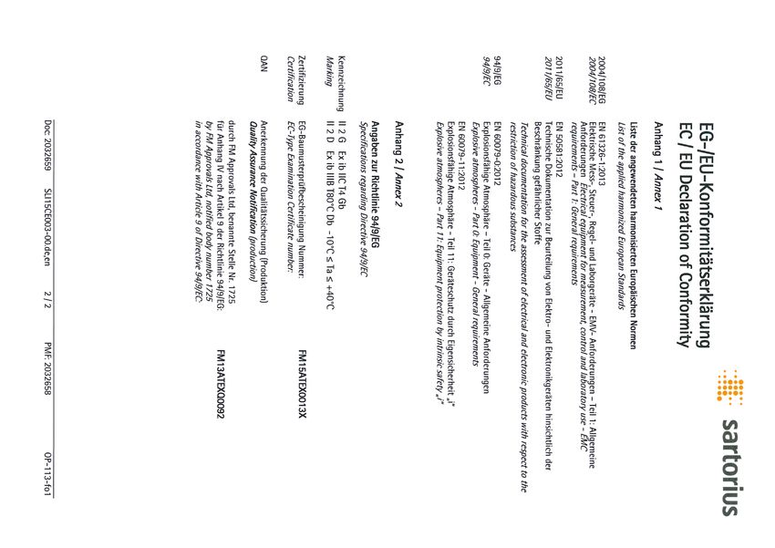
Contents User Information Warnings and Safety
Precautions
User Information. . . . . . . . . . . . . . . 2 Warning / Danger Symbols Safety Precautions
−− For Europe (EU):
Warnings and Safety Precautions. . 2 These notes identify hazards The weigh cell meets the requirements
which have a high probability of for Group II, Category 2 equipment in
General View of the Equipment. . . . 4 resulting in death or serious accordance with EC Directive 94/9/EC
physical injury if not avoided. in accordance with FM EC type-exami-
Installation . . . . . . . . . . . . . . . . . . . 5 nation certificate FM 15ATEX0013X and
Storage and Shipping Conditions . . . 5 These notes identify hazards that is certified in accordance with EC-type
Incoming Inspection. . . . . . . . . . . . . 5 can result in moderate or mild examination certificate FM 15ATEX0013X
Equipment Supplied. . . . . . . . . . . . . 5 injuries if not avoided. and the Certificate of Conformity IECEx
Ambient Conditions. . . . . . . . . . . . . 5 FMG 16.0045X.
Components Attached These notes identify hazards
to the Load Receptor . . . . . . . . . . . . 5 associated with the risk of −− For U.S. and Canada:
Connecting an Optional Display material damage. The weigh cell meets the “Hazardous
and Control Unit . . . . . . . . . . . . . . . 5 location electrical equipment per US and
Explanation of Symbols Canadian Requirements” in accordance
Conditions for Installation . . . . . . . . 6
Connecting an Equipotential with FM17US0299X, FM17CA0151X and
This symbol identifies useful the associated Control Drawing.
Bonding Conductor . . . . . . . . . . . . . 7
information and tips.
Connecting the Weigh Cell
to AC Power. . . . . . . . . . . . . . . . . . . 7 −− The weigh cell may be used in Zone 1,
Leveling the Load Receptor. . . . . . . . 8 The following symbols are used in these 2, 21 or 22 hazardous areas or Class 1,
Leveling the Weigh Cell . . . . . . . . . . 9 instructions: Division 1 or 2 hazardous locations (gas
ttindicates required steps. and dust explosion hazards). Please
Operation yydescribes what happens after you have make sure the currently valid regula-
Notes on Analytical Weighing. . . . . . 10 performed a particular step tions and guidelines for installing
Below-Cell Weighing . . . . . . . . . . . . 11 −− Texts that use this mark are lists equipment in the hazardous areas/loca-
tions listed above are strictly observed.
Factory Settings . . . . . . . . . . . . . . . 12 Conventions for these Instructions: Whether the equipment can be used in
Parameter Settings (Overview). . . . . . 14 The figures in these instructions are based a given area containing potentially
on “standard” scales. On scales verified explosive agents must be checked on a
RS-232 Interface Port. . . . . . . . . . . 17 for use in legal metrology, some dis- case-by-case basis.
Pin Assignment Chart. . . . . . . . . . . . 24 plays and reports may deviate slightly
from the figures. Where this is signifi- −− That way you will prevent damage to
Troubleshooting Guide. . . . . . . . . . . 25 cant for operation, the differences will the device.
be explained in the text.
Shipping / Disposal . . . . . . . . . . . . . 26 −− These installation instructions describe
Shipping. . . . . . . . . . . . . . . . . . . . . . 26 About These Instructions. only the technological specifications of
Disposal. . . . . . . . . . . . . . . . . . . . . . 26 ttPlease read these instructions carefully the weigh cell and the conditions that
and completely before putting the must be observed during installation.
Technical Data. . . . . . . . . . . . . . . . . 27 equipment into operation for the first
time. Observe the safety instructions. −− Read these installation instructions
Dimensions (Scale Drawings). . . . . . 28 ttThese instructions are an important part thoroughly before using your weigh
of the product. Keep these instructions cell. The weigh cell can be operated
Accessories (Options). . . . . . . . . . . . 31 in a safe place. If you give the device to indoors or outdoors.
others to use, give them these instruc-
Appendix. . . . . . . . . . . . . . . . . . . . . 32 tions too.
For Europe (EU): ttIf these instructions are lost, please Any incoming inspection, altera-
EC / EU Declaration of Conformity. . 32 contact Sartorius for a replacement or tions to the equipment or instal-
EC-Type Examination Certificate download the latest manual from our lation work that does not con-
(FM Approvals). . . . . . . . . . . . . . . . . 34 website: www.sartorius.com form to the instructions in this manual will
IECEx Certificate of Conformity . . . . 37 result in forfeiture of all claims under the
Safety Instructions. . . . . . . . . . . . . . 41 manufacturer’s warranty.
Verification of the Intrinsic Safety. . . 42 System Description
For U.S. and Canada: If you use electrical equipment
Certificates of Conformity. . . . . . . . . 48 −− The product is comprised of two in installations and under ambi-
Control Drawing. . . . . . . . . . . . . . . . 52 components: ent conditions requiring higher
FCC Supplier’s Declaration −− Compact weigh cell that can be affixed safety standards, you must comply with
of Conformity. . . . . . . . . . . . . . . . . . 55 to a smooth, even surface the provisions as specified in the applicable
−− Electronics module regulations for installation in your country.
−− These compact weigh cells can be used
to determine weights within restricted
space. ttHave the equipment inspected at
−− The weigh cells have been developed for appropriate intervals for correct func-
−− Installation in measuring devices and tioning and safety by a trained techni-
production machinery cian.
−− High-precision weighing within limited
space
−− Precise weight determination on active
production lines
2
ttOnce the weigh cell has been installed,
           Always make sure the weigh cell                                                                Be sure to unplug the system
                                                   it must be checked to ensure:
           is disconnected from AC power                                                                  from AC power before connect-
                                                −− Observance of the guidelines and stand-
           before performing any installa-                                                                ing or disconnecting any cables.
                                                   ards for using electrical equipment
tion, cleaning, maintenance or repair work.
                                                −− Electromagnetic compatibility of the                    If you are using the optional
If the equipment housing is opened by
                                                   entire device                                           YAC01NX display and control
anyone other than persons authorized by
                                                −− Compliance with mandatory safety reg-                   unit, it must be installed a way
Sartorius, all claims under the manufactur-
                                                   ulations.                                    that limits the risk of mechanical damage.
er’s warranty are forfeited. Use only origi-
                                                −− Installation in a Zone 1, 2, 21 or 22
nal Sartorius spare parts.
                                                   hazardous area or Class 1, Division 1 or               Never open the display and
          Disconnecting equipotential              2 hazardous location must be per-                      control unit.
          bonding conductors is not per-           formed by a trained technician who is
          mitted.                                  familiar with the assembly and opera-
                                                   tion of the equipment, as well as with                 If there is visible damage to the
          If you see any indication that           the procedure for putting the system                   components: disconnect the
          the weigh cell cannot be oper-           into operation. Furthermore, the trained               equipment from AC power and
          ated safely (for example, due to         technician must have the required qual-      replace the weigh cell along with the elec-
damage), turn off the unit and lock it in a        ifications and must be familiar with the     tronics module.
secure place so that it cannot be used for         relevant guidelines and regulations.
the time being. Observe the relevant safety        If you need assistance, contact the                     If you use cables purchased from
precautions and inform personnel as                system installer, your Sartorius dealer or              another manufacturer in the
required.                                          the Sartorius Service Center.                           non-hazardous area/location,
                                                   Any installation work that does not          check the pin assignments. Before con-
          The casing on all connecting             conform to the instructions in this          necting the cable to Sartorius equipment,
          cables, as well as the casing on         manual will result in forfeiture of          check the pin assignments in the cable
          wires inside the equipment               all claims under the manufacturer’s          against those specified by Sartorius and
housing, is made of PVC. Chemicals that            warranty. Be sure to observe all restric-    disconnect any wires that are assigned
corrode these materials must be kept away          tions listed in the type-examination         differently. The operator shall be solely
from these cables.                                 certificate. Operating the weigh cell        responsible for any damage or injuries that
                                                   beyond the limits imposed by these           occur when using cables not supplied by
           Make sure the weighing instru-          restrictions is not permitted and is con-    Sartorius. On request, Sartorius will provide
           ment is not exposed to sub-             sidered use of the equipment for other       information on the minimum operating
           stances that release chlorine ions      than its intended purpose.                   specifications (in accordance with the
at the place of use. If such exposure                                                           Standards for defined immunity to inter-
cannot be ruled out, the operator is                       Always make sure the weigh cell      ference).
responsible for establishing and observing                 is disconnected from AC power
appropriate safety precautions, to                         before performing any installa-                   When using the weigh cell in
be checked at regular intervals for contin-     tion, cleaning, maintenance or repair work.                  hazardous areas/locations, make
ued effectiveness.                                                                                           sure there is no current or volt-
                                                           The electronics module and the       age in the equipment before connecting or
            The weigh cell may be used and                 optional YAC01NX display and         disconnecting current-carrying cables to or
            operated by qualified personnel                control unit may not be opened.      from the weigh cell. Disconnect the weigh
            only. The permissible use of the    The weigh cell may be opened only by            cell from AC power before connecting or
equipment is defined by the equipment           authorized service technicians who have         disconnecting cables.
specifications and the relevant safety regu-    been trained by Sartorius and who follow        Avoid exposing the weigh cell to static
lations. Operating the weigh cell beyond        Sartorius’ standard operating procedures        electricity.
the specifications listed in the type-          for maintenance and repair work.
approval certificate is not permitted, and                                                               All components of the system
is considered use of the equipment for                     Avoid interchanging weigh cells               must be grounded, including
other than its intended purpose. All restric-              and electronics modules.                      any draft shields used. Be sure
tions listed in the type-examination certifi-              Connect the parts that fit           to connect an equipotential bonding
cate must be strictly observed.                 together, ensuring that the serial numbers      conductor.
                                                match.

                                                           Do not expose the weigh cell         −− If any problems arise with the weigh
                                                           unnecessarily to extreme tem-           cell that require service, please contact
                                                           peratures, aggressive chemical          your local Sartorius dealer.
                                                vapors, moisture, temperature fluctuations
                                                or vibrations. The permissible operating
                                                temperature range during operation is
                                                +5°C to +40°C.

                                                                                                                                               3
General View of the Equipment
1
2
3
4
5
6
7
8
9
10
Pos. Designation Pos. Designation
1 Electronics module 6 DC jack
2 Read these installation instructions thoroughly before using 7 Load receptor
your weigh cell. 8 Weigh cell
3 Socket for connecting an optional display and control unit 9 Level indicator
4 Connection for weigh cell 10 Threaded hole (M6) for mounting the weigh cell
5 Connection for optional Zener barrier
4Installation
The weigh cells are available in various Equipment Supplied Conditioning the Equipment:
versions. If you have ordered special – Weigh cell Moisture in the air can condense on the
options, the weigh cells are equipped – Electronics module surface of a cold weighing instrument
with the specified features at the factory. – Installation instructions (this document) or other device whenever it is moved
– Special accessories as listed on the bill to a substantially warmer place. If you
Storage and Shipping Conditions of delivery, if ordered, or in accordance transfer the equipment to a warmer
– Once the equipment has been removed with specific arrangement. area, make sure to condition it for
from the packaging, it may lose accu- about 2 hours at room temperature,
racy if subjected to strong vibration. Ambient Conditions leaving it unplugged from AC power.
Excessively strong vibration may com- The equipment is designed to provide
promise the safety of the equipment. reliable results under normal ambient Components Attached to the Load
– Do not expose the equipment unneces- conditions. If you have any questions Receptor
sarily to extreme temperatures, mois- or difficulties when developing your – Components that are attached to the
ture, shocks or vibration. weighing system, please contact the load receptor can adversely affect the
$ It is a good idea to save the box and all specialists at Sartorius. When designing way the weigh cell functions. The user
parts of the packaging until you have and setting up your weighing system, is responsible for how the series is used
successfully installed your equipment. please observe the following so that and the specifications achieved for the
Only the original packaging provides you will be able to work with added entire system. Your specifications may
the best protection for shipment. speed and accuracy: differ from those listed in the section
$ Before packing your equipment, unplug – Avoid exposing the equipment to the entitled “Specifications.”
all connected cables to prevent damage. effects of extremely high temperatures;
$ Do not expose the equipment to for example, caused by other electronic
gravitational acceleration in excess of components, heaters or direct sunlight.
0 300 m/s2 (unless additional equip- – Protect the equipment from drafts that
ment is installed on the load receptor come from open windows or doors.
that enables it to withstand this force). – Avoid exposing the equipment to exces-
sive vibrations during weighing; for
example, caused by motors or valves.
Incoming Inspection – Protect the equipment from aggressive
The customer shall inspect the product chemical vapors.
and packaging immediately upon deliv- Switch the system to the standby mode
ery for proper functioning, complete- when not in use.
ness, and absence of defects. This is to
be performed in an incoming inspection
within 10 days of delivery of the prod-
uct. The incoming inspection must take
place before the equipment is installed.
Any obvious defects, errors, or incorrect
delivery must be reported in writing.
Defects detected at a later date must
be reported in writing immediately
upon detection.
Be sure to perform the following as part
of the incoming inspection:
– We recommend performing a repeata-
bility test using an auxiliary draft shield
to make sure the weigh cells were not
damaged in transport. You can use the
“Sartorius CAS-Suite” software or the
optional YAC01NX display and control
unit as an aid for this test. Connecting an Optional YAC01NX Display
and Control Unit
The display and control unit can
only be connected if specified
directly at the time the order is
placed.
Protect the YAC01NX display
and control unit from mechani-
cal damage. If you discover that
the equipment has been damaged, discon-
nect it from AC power and remove it from
service.
5YPSC01-Z ..
Conditions for Installation The explosion-protected weighing system must be installed in
Before putting the equipment into operation, it is important to accordance with acknowledged rules of engineering. These include
make sure that the power cord on the associated power supply is national and international laws and regulations (such as VbF,
correctly connected to the power outlet (mains supply). All equip- EX-RL, DIN EN 60079-14, DIN VDE 0166, DIN VDE 0100, DIN VDE
ment must be connected to the equipotential bonding conductor 0101, and DIN VDE 0800).
by connecting the grounding cable (not included in delivery) to the In particular, the conditions described under Item 17 of the KEMA
grounding terminals provided for this purpose on each device. EC type-examination certificate, “Special Conditions for Safe Use,”
The dimensions of the grounding cable are specified in national must be observed. Furthermore, national regulations for accident
regulations for electrical installations. Installation must be per- prevention and environmental protection must be observed at all
formed by a trained technician in accordance with national regula- times.
tions and acknowledged technological standards.
Before you operate your weigh cell in a hazardous area/location,
Use only cabling and extensions approved by Sartorius, as these are it must be inspected either by a certified electrician or under the
made in accordance with the restrictions on permissible cable lengths guidance and supervision of a certified electrician to make sure that
imposed by both the capacitance and inductivity values and the the weigh cell complies with the applicable regulations. Determine
requirements for electromagnetic compatibility (see the EC Type- whether your weigh cell must be reported to the technical inspec-
Examination Certificate). tion authorities (such as the trade board) in your country. The system
must also be inspected during operation. The system should be
Before putting the weighing system into operation for the first inspected at intervals which allow for early detection of the faults
time, make sure there is no hazard of explosion present at the place that occur as a result of normal wear and tear, so that they can
of installation. If there is any indication that the equipment does be corrected before damage is caused. In any case, inspection must
not function properly (e.g., display remains blank or is not backlit) be performed at least every 3 years. Other conditions and standards
due to damage during transport: that regulate the installation and operation of the equipment and
– disconnect the equipment from power and are applicable in your country must be met as well. When perform-
– notify your nearest Sartorius Service Center. ing inspections, generally acknowledged rules of engineering rel-
evant to these conditions must also be applied. If the unit housing
The weigh cell specifications for Ui, Li, Pi, Ta, temperature class, is opened by anyone other than persons authorized by Sartorius,
Ci, and Li are listed in the EC type-examination certificate. or if the equipment is installed or operated incorrectly, this will
This certificate also specifies the display and control unit models result in forfeiture of the approval for use in the stated hazardous
that can be used with these weigh cells. area(s)/location(s) and of all claims under the manufacturer’s
warranty.
6ttConnecting an Equipotential Bonding Conductor (Grounding)
−− If the weigh cell is in a hazardous area/location, it must be grounded (i.e., an equipoten-
tial bonding conductor must be connected). This connection should be made by
a trained technician. The weigh cell is equipped with a connector for the grounding con-
ductor. The position is marked by the symbol shown here, indicating the grounding con-
nection.
Use a stainless steel screw (M6 thread) to connect the grounding conductor.
We recommend using a tooth lock washer to prevent the screw from coming loose.
The wire used for the grounding conductor should have a cross-sectional diameter of at
least 4 mm2, with a suitable ring lug attached.
The grounding cable must be installed in such a way that it is not under mechanical
stress and so the screw will not become loose. Connect all equipment, including periph-
eral devices, to the equipotential bonding conductor.
Connecting the Weigh Cell to AC Power
ttBefore putting the weigh cell into operation, make sure that the power cable is
correctly connected to the electrical outlet; it is especially important to make sure
the grounding cable is attached to the housing of the power supply. All devices used
must be connected to the equipotential bonding conductor via the retainers provided on
each device. Installation must be carried out by a certified electrician according to the
valid standards of technology.
Before putting the equipment into operation for the first time, make sure that the
area of installation is not hazardous. If the equipment shows any signs of mal-
function as a result of damage during shipment (display remains blank, display
not backlit even with a weight readout, weight value not repeatable, readout does not
stabilize, etc.), disconnect the equipment from AC power and contact a Sartorius service
technician.
ttYPSC01-X: flameproof power supply:
−− Lay both cables in a manner that is secure and protected.
−− Flexible installation of cables with threaded fasteners can be carried out on request.
ttCheck the voltage rating and the plug design.
−− If they do not match the rating or standard you use, contact your Sartorius office or dealer.
−− Use only original Sartorius power supplies:
−− YPC01-Z... (for use outside hazardous areas/locations)
−− YPC01-X (for use within hazardous areas/locations)
To operate the weigh cell in a hazardous area or location, please comply with the
following:
– Currently valid standards and regulations for installation of explosion-protected
equipment in such areas
– Installations in Zone 1 must be carried out and checked by a certified electrician.
ttPlug the female connector of the blue intrinsically safe power supply cable into the
socket on the weigh cell. Secure this connection by tightening the knurled collar.
Be sure to connect the power supply to the electronics module before plugging
the equipment in to AC power.
Install the power cable so that it is protected from damage.
The intrinsically safe connector for the power cable (primary side) is not part of
the standard equipment supplied (open cable ends).
Connecting Electronic Peripheral Devices
Make absolutely sure to unplug the weigh cell from AC power before you connect
or disconnect a peripheral device (display and control unit or PC) to or from the
interface port.
7Warmup Time
The amount of warmup time required depends in part on the system in which the
weigh cell is installed. To deliver exact results, the weigh cell must warm up for at
least 30 minutes after it is connected to power for the first time. Only after this
time will the device have reached the required operating temperature.
Leveling the Load Receptor and User-Specific Transducer
ttRemove the (S1) screw.
ttUse the (S2) screws to radially position and level the load receptor (minor height adjust-
ment also possible).
ttAttach the (S1) screw to affix the load receptor and tighten it as indicated in the table
below listing the torque values.
ttAttach any user-specific transducer to the threaded fastener (S3) on the load receptor and
tighten it as indicated in the table below: Maximum load on load receptor.
ttThe user-specific transducer must be rigid and securely connected to the load receptor.
Maximum load on load receptor:
R
Model Meck S1 S2 S3
G WZA623-NX 2.5 Nm 1 Nm 1 Nm 2 Nm
WZA6202-NX 6 Nm 4 Nm 2 Nm 4 Nm
If the load is not centered on the load receptor, the corner load moment Meck may not be
exceeded, since this could lead to a defect in the weigh cell.
The force “G” is comprised of the weight of the sample and the non-centric load on the
weigh cell.
The load receptors should be constructed so that they are stiff and cannot be bent or
G = Load twisted.
R = Distance from the center of the pan
Meck = G . R Example: What is the maximum permissible length of the cantilever
(on WZA623-NX in this instance)?
It is assumed that the load is connected to a cantilever that has a uniform width.
The cantilever utilizes the necessary preload of 600 grams on the WZA623-NX.
Meck Arm ~ 1 R + GArm = 9.81 m/s2 + 0.6 kg
GArm
= 5.9 N
Meck Last = R + GLast GLast = 9.81 m/s2 + 0.62 kg
= 6.1 N
Meck = Meck Arm + Meck Last
= R (1 + GArm + GLast)
Meck The maximum length that the cantilever
R = ——————————— can be without destroying the system is
(1 GArm + GLast)
200mm. As a result of handling, other
moments can occur, which must be taken
R = 2.5 Nm / 12 N = 0.2 m
into consideration. In general, we recom-
R = 0.2 m
mended testing first because there can
be undesired repercussions. Drafts can
influence results as well.
8Leveling the Weigh Cell in a Portable Weighing System (Leveling Feet Optional)
Purpose:
– To compensate for uneven areas at the place of installation
– To ensure that the weigh cell is placed in a perfectly horizontal position for consistently
reproducible weighing results
– Always level the weigh cell again any time after it has been moved to a different location.
§ Adjust the leveling feet until the air bubble is centered within the circle on the level
indicator.
Permanently Installed Weigh Cells
– Adjust the weigh cell after it has been installed in the system in its permanent location
(see next page).
The weigh cell must be leveled again any time the location or position of the weighing
system is changed.
– For optimum operation, install the weigh cell in a horizontal position.
1 1) Bottom plate of the weighing cell
2) Fastening frame of the system
2 § Fastening with M6 screws:
Connection to the threaded fasteners on the weigh cell (1): torque: 2.5 Nm
1 § Fastening with M4 screws:
Connection to the threaded fasteners of a user-specific frame (2).
2
Device-Specific Information: Coding of the Serial Number
The year that the device was manufactured is coded in the serial number.
The format is as follows:
YMM x x x x x
Y Year
3 2014–2020 6 2035–2041
4 2021–2027 7 2042–2048
5 2028–2034 8 2049–2055
9 2056–2062
Each number in the Y column represents a group of seven years during which the device
was manufactured. Within each group of years, the months of the year (M M) advance
chronologically from 13 upwards.
Year: 2015 2016 2017 ...
MM: 25-36 37-48 49-60 ...
Example:
328xxxxx (April 2015)
xxxxx is a consecutive number that is counted upward after being reset each month.
9Operation
Notes on Analytical Weighing Electrostatically Charged Weighing Magnetic or Magnetizable
Samples or Containers Samples
Weighing with Weigh Cells If a sample or container is electrostati- For technical reasons, the use of mag-
cally charged, significant errors may netizable materials in the manufacture
Handling of Samples and Containers result during weighing. Materials with of weigh cells is unavoidable, primarily
Samples should be acclimatized to the low conductivity, such as glass, plastic because the operating principle of high-
temperature of the weigh cell to avoid or filters, are particularly susceptible to resolution weigh cells is based on
negative effects on results, such as static electricity (resulting, e.g., from compensation of the load through
measurement errors and fluctuations friction) because the weighing pan can magnetic forces.
caused by air buoyancy resulting from discharge the static electricity only very
convection currents across the surface slowly. When weighing magnetic or magnetiz-
of the sample. able samples or containers, interaction
The result is a force action between between the sample or container and
These negative effects increase as the the charge on the sample and the per- certain parts inside the weigh cell may
volume and/or surface area of the sam- manently installed parts of the weigh have a distorting effect on the weighing
ple increases. For this reason, the size of cell. This causes the readout to fluctu- results.
the container should be appropriate for ate constantly.
the sample. To keep such effects to a minimum,
Ionization can be applied to make the we recommend increasing the distance
Samples and containers should not be air around the sample conductive. This between the sample/container and the
touched by the operator’s hands, as the allows the charge to be compensated weighing system using a non-magnetic
hygroscopic effect of fingerprints and through the air, or discharged through material. The force is reduced quadrati-
the effect of the hand’s temperature the ground (grounded). cally with the increase in distance.
can influence the measurement results. The area around the weigh cell can
also contain charges that negatively Magnetizable or magnetized samples
Samples must be applied very carefully, affect the accuracy of weighing results. and the weigh cell itself interact with
whether manually (using forceps) or Appropriate steps taken in the design magnetic fields and magnetizable or
automatically (by a robot or filling of a draft shield device can counteract magnetized parts in the area surround-
system). such effects. In the process, be sure to ing the weighing system. The system
install devices that are suitable for use can be shielded from external magnetic
When designing a draft shield device, in the particular hazardous zones. fields to some extent using (soft mag-
steps must be taken to keep the netic) plates.
increase in temperature within the
weighing chamber to a minimum
(e.g., using a bypass).
Calibration/Adjustment
Calibration/adjustment can be per-
formed as follows:
– Using control commands sent by the
CAS-Suite configuration software from
Sartorius, installed on a computer
(see page 18 for the commands)
or
−− Using the optional YAC01NX display
and control unit
10Below-Cell Weighing
A port for a below-cell weighing hanger is located on the bottom of the weigh cell.
ttRemove the cover plate.
−− Threaded fastener for hook: M3
Overload protection
−− Standard feature on the WZA623-NX model
Models WZA6202-NX:
No overload protection provided
ttCarefully install the special hook: maximum torque: 0.75 Nm
−− If necessary, install a shield for protection against drafts.
Protection rating: only IP22 is provided when the cover plate for the below-cell
weighing port has been removed.
11Factory Settings (Setup)
Purpose Factory Settings for the Parameters
−− The weigh cell is configured at the fac- Factory-set configurations are marked
tory. The factory settings can be with “o.” Customer-specific settings
adapted to individual requirements by can be configured on request.
editing the “Setup” menu.
Preparation
Features The following operating menu
Parameters are combined into the functions can be carried out using
following groups the Sartorius CAS-Suite configuration
(1st menu level): software installed on a PC:
1. Setup: Balance parameters – Read
2. Device parameters – Change
3. Data output – Print
4. Application program1) – Save
5. Input
6. Information or
7. Language setting
With one of the optional YAC01NX
control units
1
) Detailed instructions on the available
application programs can be found
in the operating instructions for the
Cubis Series, MSE Models, which can be
downloaded online:
Go to www.sartorius.com –
Service Center ➝ Downloads.
12Menu Structure (Overview)
Level 1 Level 2 Level 3 Menu level info
1) Setup
Bal.Scal. Ambient Ambient conditions 1. 1. 1.
(Weigh cell functions) app.filt. Application filter 1. 1. 2.
Stab.rng. Stability range 1. 1. 3.
Stab.dly Stability delay 1. 1. 4.
Taring Taring 1) 1. 1. 5.
Autozer. Auto zero 1. 1. 6.
Wt.Unit Basic weight unit 1. 1. 7.
Display Display accuracy 1) 1. 1. 8.
Cal./adj. Function of the C key 1. 1. 9.
Cal.routine Calibration/adjustment routine 1. 1. 10.
Zerorng. Zero range 1. 1. 11.
Zero.on Zero at power on 1. 1. 12.
On.tare Tare/zero at power on 1. 1. 13.
Cyc.rate Output rate 1. 1. 14.
isocal Auto calibration/adjustment 1. 1. 15.
EXT.Cal. External adjustment 1. 1. 16.
cal.unit Weight unit for calibration 1) 1. 1. 17.
gen.serv. General service men.reset Factory settings 1. 9. 1.
2) Device
extras menu Menu read only/can edit 2. 1. 1.
(Additional functions) Signal Acoustic signal 2. 1. 2.
Keys (Keypad) 2. 1. 3.
Ext.Key External switch function 2. 1. 4.
Onmode Power-on mode 2. 1. 6.
Peripher. dat.rec. Communication mode 2. 2. 1./2. 3. 1.
(25-pin “Peripherals” interface) Baud Baud rate 2. 2. 2./2. 3. 2.
parity Parity 2. 2. 3./2. 3. 3.
pc-usb (USB port “PC”) Stopbit Number of stop bits 2. 2. 4./2. 3. 4.
Handshk. Handshake mode 2. 2. 5./2. 3. 5.
databit Number of data bits 2. 2. 6./2. 3. 6.
3) Dataout com.sbi com.out Communications output 3. 1. 1.
(Data output) (PC communication) Stop Stop automatic output 3. 1. 2.
Aut.Cycl. Time-dependent automatic data output 3. 1. 3.
Format (Line format) 3. 1. 4.
Auto.Tare Auto taring after data output 3. 1. 5.
Print.para Parameters for printing Res. Print resolution (manual/automatic) 3. 2. 1.
Format Line format for printout 3. 2. 2.
Prt.Init. Printout of appl. parameters 3. 2. 3.
GLP ISO/GLP-compliant printout 3. 2. 4.
tar./prt. Tare bal./scale after ind. print 3. 2. 5.
time: 12 h/24 h 3. 2. 6.
date Date format 3. 2. 7.
4) Applic.ation programs1)
5) Input Input ID. ID input; max. 7 characters 5. 1.
Date Set date 5. 2.
Time Set time 5. 3.
Password Password entry (for service) 5. 4.
Cal.wt. Enter weight value 5. 5.
6) Information Version, Ser.no., model, Display of software version, serial no., model 6. 1. to 6. 6.
lobs, kdcvers, DR.Shield, if OPT.MOD
7) Language English English (factory setting) 7. 1.
Deutsch German 7. 2.
franc. French 7. 3.
ital. Italian 7. 4.
Espanol Spanish 7. 5.
Russian 7. 6.
Polski Polish 7. 7.
1
) Detailed instructions on the available application programs can be found in the operating instructions for the „Signum series,“ which can be downloaded online:
Go to www.sartorius.com – Service Center Downloads.
13Parameter Settings: Overview ο = factory setting; √ = user-defined setting Info about Level 1 Level 2 Level 3 Level 4 menu level 1) Setup Bal.Scal. Ambient Ambient conditions V.Stable Very stable 1. 1. 1. 1 Balance (filter adjustment) ο Stable Stable 1. 1. 1. 2 parameters unstabl Unstable 1. 1. 1. 3 v.unstbl. Very unstable 1. 1. 1. 4 App.Filt. Application filter ο Final.rd. Final readout mode 1. 1. 2. 1 Filling Filling mode 1. 1. 2. 2 Reduc. Reduced 1. 1. 2. 3 Off Off 1. 1. 2. 4 Stab.rng. Stability range Max.acc. Maximum accuracy (1⁄4 digit) 1. 1. 3. 1 V.acc. Very accurate (1⁄2 digit) 1. 1. 3. 2 Acc. Accurate (1 digit) 1. 1. 3. 3 ο Fast Fast (2 digits) 1. 1. 3. 4 V.fast Very fast (4 digits) 1. 1. 3. 5 Max.fast Maximum speed (8 digits) 1. 1. 3. 6 St.del. Stability delay No No delay 1. 1. 4. 1 ο Short Short delay 1. 1. 4. 2 Averg. Average delay 1. 1. 4. 3 Long Long delay 1. 1. 4. 4 Tare Tare wiostb. Without stability 1. 1. 5. 1 ο Wistb. After stability 1. 1. 5. 2 Atstab. At stability 1. 1. 5. 3 Aut.zero ο on Automatic zeroing on 1. 1. 6. 1 Auto zero off Automatic zeroing off 1. 1. 6. 2 WT.UNIT For list of units, see 1. 1. 7. 1 Basic weight unit “Toggling between weight units” to 1. 1. 7.24 Disp.dig. ο all Display all digits 1. 1. 8. 1 Display accuracy lp.on.off Last digit after load change 1. 1. 8. 2 Increment of measured values one level lower 1. 1. 8. 3 Increment of measured values two levels lower 1. 1. 8. 4 Increment of measured values three levels lower 1. 1. 8. 5 Incrm.1 Last digit single increment 1. 1. 8. 6 Minus 1 Reduced by one digit 1. 1. 8. 7 Resolution by a factor of 10 1. 1. 8.14 Cal./Adj. EXT.Cal. External calibr./adjustment with factory-set weight 1. 1. 9. 1 Function of C key cal.e.usr. External calibr./adjustment with user-defined weight 1. 1. 9. 3 ο cal.int. Internal calibr./adjustment 1. 1. 9. 4 lin.int. Internal linearization (on analytical balances only) 1. 1. 9. 5 lin.ext. External linearization with factory-set weights 1. 1. 9. 6 lin.usr. External linearization with user-defined weights 1. 1. 9. 7 set.prel. Set the preload 1. 1. 9. 8 clr.prel. Delete the preload 1. 1. 9. 9 blocked C locked 1. 1. 9.10 Select Select 1. 1. 9.12 set.ext.w. Determine ext. calibration weight for cal.e.usr 1. 1. 9.17 Determine internal weight 1. 1. 9.18 Cal./Adj. Calibration/adjustment ο Sequence Sequence adjustment 1. 1.10. 1 CAL/adj. Adjustment as needed 1. 1.10. 2 Zerorng. Zero range 1perc. 1 percent of max. load 1. 1.11. 1 ο 2perc. 2 percent of max. load 1. 1.11. 2 5perc. 5 percent of max. load 1. 1.11. 3 10perc. 10 percent 1. 1.11. 4 default (factory-set) 1. 1.11. 5 init.zero Zero at power on ο default (factory-set) 1. 1.12. 1 2perc. Initial zero 2 percent 1. 1.12. 2 On. Tare Tare/zero at power on ο On Init. tare/zero on 1. 1.13. 1 Off Init. tare/zero off 1. 1.13. 2 5perc. 5 percent 1. 1.13. 3 10perc. 10 percent 1. 1.13. 4 20perc. 20 percent 1. 1.13. 5 50perc. 50 percent 1. 1.13. 3 100perc. 100 percent 1. 1.13. 7 cyc.rate Output rate ο normal Normal output 1. 1.14. 1 highvar. High var. output 1. 1.14. 2 slow Slow output 1. 1.14. 3 medium Medium output 1. 1.14. 4 fast Fast output 1. 1.14. 5 veryfast Very fast output 1. 1.14. 6 maximum Max. output 1. 1.14. 7 ISOcal Auto calibration/adjustment ο Off Auto cal./adj. off 1. 1.15. 1 Note Info 1. 1.15. 2 On Auto cal./adj. on 1. 1.15. 3 Ext.cal. External calibration ο free Unlocked 1. 1.16. 1 locked Locked 1. 1.16. 2 cal.unit ο Gram Grams 1. 1.17. 1 Unit for calibration weight Kilogr. Kilograms 1. 1.17. 2 Userdef. User-defined unit (factory setting: pounds) 1. 1.17. 4 gen.serv. men.Reset Menu reset Yes Restore factory settings 1. 9. 1. 1 General service (factory settings) ο No Do not restore factory settings 1. 9. 1. 2 Standard Standard settings 1. 9. 1. 3 Verifiable Verifiable settings 1. 9. 1. 4 14
Level 1           Level 2                   Level 3   Level 4                     Menu level info

2) Device
 extras      menu                    ο canedit Can edit                           2. 1. 1. 1
 (Additional			                        Rd.only Read only                          2. 1. 1. 2
 functions)
		           Signal Acoustic signal		 off Acoustic signal off                     2. 1. 2. 1
			                                  ο on Acoustic signal on                      2. 1. 2. 2

		 Keys Keypad ο free Unlocked                                                    2. 1. 3. 1
				             locked Locked                                                    2. 1. 3. 2

		 Ext.Key                  ο Print P key (print)                                 2. 1. 4. 1
		 External switch function   Z/Tare J key (tare)                                 2. 1. 4. 2
				                          cal. C key (calibrate)                              2. 1. 4. 3
				                          cf F key (go back/exit)                             2. 1. 4. 5
				                          enter V key (enter)                                 2. 1. 4. 6
				                          Dr.shield Draft shield                              2. 1. 4. 9
				                          Ionizer Ionizer                                     2. 1. 4. 10
				                          appl. Application key                               2. 1. 4. 11
				                          Asterisk * key                                      2. 1. 4. 12

		 onmode 		 off/on/sb Off/On/Standby                                             2. 1. 6. 1
		 Power-on mode		 off/on/SO Off/On/Auto shut-off                                 2. 1. 6. 2
				                on/sb On/Standby                                              2. 1. 6. 3
			               ο AutoOn Auto on                                                2. 1. 6. 4

					                                                                             Periphery:/PC USB:
 Peripher.           dat.rec.        ο SBI (ASCII)                                2. 2. 1. 1/2. 3. 1. 1
 (25-pin “Peri-      Operating mode		 XBPI                                        2. 2. 1. 2/2. 3. 1. 2
 pherals” interface)			 Rem.displ. Remote display                                 2. 2. 1. 4/2. 3. 1. 4
				                                   uni.Print Universal printer                2. 2. 1. 7/2. 3. 1. 7
 pc usb			                             lab.print (Parameters for YDP10 printer)   2. 2. 1. 8/2. 3. 1. 8
 (USB port for PC)			 OFF Interface off                                           2. 2. 1.10/2. 3. 1.10

		 Baud Baud rate		600                                                            2. 2. 2. 3/2. 3. 2. 3
			                ο 1200                                                         2. 2. 2. 4/2. 3. 2. 4
				                 2400                                                         2. 2. 2. 5/2. 3. 2. 5
				                 4800                                                         2. 2. 2. 6/2. 3. 2. 6
				                 9600                                                         2. 2. 2. 7/2. 3. 2. 7
				                 19200 1)                                                     2. 2. 2. 8/2. 3. 2. 8
				                 38400 1)                                                     2. 2. 2. 9/2. 3. 2. 9
				                 57600 1)                                                     2. 2. 2.10/2. 3. 2.10
				                 115200 1)                                                    2. 2. 2.11/2. 3. 2.11

1
 ) Only one of the two interfaces can be used.

                                                                                                          15
Level 1 Level 2 Level 3 Level 4 Menu level info
Periphery:/PC USB:
2) Device peripher. Parity ο Odd Odd parity 2. 2. 3. 3/2. 3. 3. 3
pc usb Parity Even Even parity 2. 2. 3. 4/2. 3. 3. 4
None No parity 2. 2. 3. 5/2. 3. 3. 5
StopBit ο 1Stop 1 stop bit 2. 2. 4. 1/2. 3. 4. 1
Number of stop bits 2Stop 2 stop bits 2. 2. 4. 2/2. 3. 4. 2
Handshk. Softw. Software 2. 2. 5. 1/2. 3. 5. 1
Handshake mode ο Hardw. Hardware 2. 2. 5. 2/2. 3. 5. 2
# None No handshake 2. 2. 5. 3/2. 3. 5. 3
DataBit 7Bits 7 data bits 2. 2. 6. 1/2. 3. 6. 1
Number of data bits ο 8Bits 8 data bits 2. 2. 6. 2/2. 3. 6. 2
3) dataout Comm.SBI COM. Output in.wio Without stability 3. 1. 1. 1
Data PC Manual/automatic ο IN. After After stability 3. 1. 1. 2
output communication IN.at At stability 3. 1. 1. 3
Auto.wio Auto without stability 3. 1. 1. 4
Aut.With Auto with stability 3. 1. 1. 5
Stop ο off Auto output off 3. 1. 2. 1
Auto output on Auto output on 3. 1. 2. 2
Aut.Cycl. ο Every 3. 1. 3. 1
Time-dependent automatic data output 2ndvalue 3. 1. 3. 2
Format Line format ο 16chars (digit not identified) 3. 1. 4. 1
22chars (digit identified) 3. 1. 4. 2
Extr.line (date, time, and weight value) 3. 1. 4. 4
Auto.Tare ο Off Auto tare off 3. 1. 5. 1
Auto taring after data output On Auto tare on 3. 1. 5. 2
Print.para res.olution Manual without Manual without stability 3. 2. 1. 1
Parameters (manual/auto) ο man.after Manual after stability 3. 2. 1. 2
for printing man.at Manual at stability 3. 2. 1. 3
auto.lc Auto at load change 3. 2. 1. 6
Format Line format for printout 16chars (digit not identified) 3. 2. 2. 1
ο 22chars (digit identified) 3. 2. 2. 2
Extr.line (date, time, and weight value) 3. 2. 2. 4
Prt.Init. Printout off Printout off 3. 2. 3. 1
of application parameters ο all Print all parameters 3. 2. 3. 2
Mainpar. Print main parameters 3. 2. 3. 3
GLP ISO/GLP- ο off Printout off 3. 2. 4. 1
compliant printout cal.adj. For calibration/adjustment only 3. 2. 4. 2
Always Printout always on 3. 2. 4. 3
tar./prt. ο off Taring off 3. 2. 5. 1
Tare bal./scale after individual print on Taring on 3. 2. 5. 2
Time ο 24h 24 h display 3. 2. 6. 1
12h 12 h display (AM/PM) 3. 2. 6. 2
Date ο dd.mmm.yy Date format 3. 2. 7. 1
mmm.dd.yy Date format 3. 2. 7. 2
# = Factory setting for “PC-USB” interface
16RS-232 Interface Port
Purpose Features
The weigh cells are equipped with
a data interface for connection to Type of interface: Serial interface
a computer or other peripheral device. Operating mode: Full duplex
Computer Standard: RS-232
You can connect a computer to alter, Transmission rates: 600 to 115,200 baud
start or monitor weigh cell functions. Parity: Space, odd, even
Character format: Start bit, 7-bit ASCII, parity 1 or 2 stop bits
Handshake mode: For 2-wire interface: software (XON/XOFF)
For 4-wire interface: hardware (CTS/DTR)
Operating mode: SBI (ASCII), XBPI*
* XBPI operating mode:
Always with 9600 baud, 8-bit, parity odd, 1 stop bit.
There are numerous additional commands for communicating with the weigh cell.
Please contact Sartorius for more information about their operation.
Protocols
For data exchange, the interfaces are configured with the following protocols:
– Printer output
– SBI (Sartorius Balance Interface): Sartorius standard protocol for output to a PC or control
unit. This simple ASCII-based protocol allows you to use ESC commands from your PC to
control the basic weighing functions.
– xBPI (eXtended Balance Processor Interface, also known as X-Bus): Binary protocol with
extended scope of commands. This protocol lets you control numerous weighing func-
tions. For further information on this, please contact Sartorius. To use the protocols,
application software must be installed on the PC.
Synchronization
During data communication between balance and PC, messages consisting of ASCII or
binary characters are transmitted via the interface. For error-free data exchange, parame-
ters for baud rate, parity, handshake mode, and character format must be identical for
both units. You can configure the respective settings in System Settings (menu).
In addition to these settings, data output for the balance can also be made dependent on
several conditions that are defined in the individual tasks. These conditions are described
under each of the tasks.
17Data Output
You can define the data output parameter so that output is activated either when a print
command is received or automatically synchronized with the display or at defined intervals
(see application programs and autoprint settings).
Data Output following Print Command The print command can be transmitted by pressing the P key or by a software command (EscP).
Automatic Data Output In Autoprint mode, data is output to the data interface port without an extra print
command. You can have synchronized data output automatically at defined display update
intervals, with or without the stability parameter. The interval time depends on the balance
operating status and balance type.
If the automatic data output is activated in the Device Configuration, it starts immediately
after the balance is turned on. You can also configure whether the automatic data output
can be stopped and started with the P key.
Data Output Formats
You can output the values displayed in the line for measured values and weight units with or
without an ID code. Configure this output parameter in the Device Parameters menu (Menu
> Device parameters > Configure data output > Line format).
Example: Output without Identification + 253 pcs 16 characters are printed
Example: Output with Identification Qnt + 253 pcs 22 characters are printed
Data Output Format with 16 Characters
Display segments that are not activated are output as spaces.
The type of character that can be output depends on the character‘s position:
Position 1 2 3 4 5 6 7 8 9 10 11 12 13 14 15 16
+ A A A A A A A * E E E CR LF
or – . . . . . . . * * *
or * * * * * * * * *
*: Space CR: Carriage return
A: Displayed characters LF: Line feed
E: Unit characters . : Decimal point
Special Outputs
Position 1 2 3 4 5 6 7 8 9 10 11 12 13 14 15 16
* * * * * * * * * * * * * * CR LF
or H i g h
or L o w
or C a l . E x t .
*: Space High: Overload
Cal. Ext.: Adjustment, external Low: Underweight
Error Message
Position 1 2 3 4 5 6 7 8 9 10 11 12 13 14 15 16
E r r * # # # * * * * CR LF
A P P . E R R1) * * * * CR LF
D I S . E R R1) * * * * CR LF
P R T . E R R1) * * * * CR LF
*: Space # # #: Error code
1
) For cause and solution, please refer to the “Troubleshooting Guide”
18Example: Output of the weight value + 123.56 g
Position 1 2 3 4 5 6 7 8 9 10 11 12 13 14 15 16
+ * * * 1 2 3 . 5 6 * g * * CR LF
Position 1: Plus or minus sign or space
Position 2: Space
Positions 3 – 10: Weight value with decimal point; leading zeros are output as spaces.
Position 11: Space
Position 12 – 14: Characters for unit of measure or space
Position 15: Carriage return
Position 16: Line feed
Data Output Format with 22 Characters
When data is output with an ID code, the 6-character code precedes the 16-character string described above.
These six characters identify the subsequent value.
1 2 3 4 5 6 7 8 9 10 11 12 13 14 15 16 17 18 19 20 21 22
K K K K K K + * A A A A A A A A * E E E CR LF
* * * * * – . . . . . . . . * * *
* * * * * * * * *
K: ID code character E: Unit characters
*: Space CR: Carriage return
A: Displayed characters LF: Line feed
Example:
1 2 3 4 5 6 7 8 9 10 11 12 13 14 15 16 17 18 19 20 21 22
N + 1 2 3 . 5 6 * g * * CR LF
SBI Setting:
In the “SBI” setting (menu code 1. 5. 6. 1), the non-verified display digit is not automatically identified.
Please take the corresponding measures or adjust the settings on the peripheral device.
Special Outputs
1 2 3 4 5 6 7 8 9 10 11 12 13 14 15 16 17 18 19 20 21 22
S t a t * * * * * * * * * * * * * * * * CR LF
H i g h
L o w
C a l . E x t .
*: Space High: Overload
Cal. Ext.: Adjustment, external Low: Underweight
Error Message
1 2 3 4 5 6 7 8 9 10 11 12 13 14 15 16 17 18 19 20 21 22
S t a t * * * * * E R R * # # # * * * * CR LF
S t a t * * * * * A P P . E R R 1) * * * * CR LF
S t a t * * * * * D I S . E R R 1) * * * * CR LF
S t a t * * * * * P R T . E R R 1) * * * * CR LF
*: Space # # #: Error code
1
) For cause and solution, please refer to the “Troubleshooting Guide”
Data Output Rates – Values per Second
Ambient Conditions (filter adjustment) XBPI / SBI “Autoprint”
Very stable (1.1.1.1) 20 20
Stable (1.1.1.2) 10 10
Unstable (1.1.1.3) 5 5
Very unstable (1.1.1.4) 2.5 2.5
19Data Input (Compatibility with Current Weigh Cells)
SBI Commands (Data Input Format)
The computer connected via the data port can send control commands to the balance to
control balance and application program functions.
These control commands may have different formats and contain up to 20 characters. Each
of these characters must be sent based on the setup configuration for data transmission.
Formats for Control Commands (Syntax)
Format 1: Esc ! CR LF
Format 2: Esc ! # _ CR LF
Esc: Escape
!: Command character
#: Number
&: Parameter (number or letter)
_: Underscore (ASCII: 95)
CR: Carriage return (optional)
LF: Line feed (optional)
Examples:
Format 1: Esc P
Format 2: Esc x1_
20Overview of SBI Commands
Format Comment Action/Function Note
1 ESC P Print at the interface sending the print request
According to menu settings; with/without stability
1 ESC T “TARE” key; taring and zeroing
1 ESC K Filter “Very stable conditions”
1 ESC L Filter “Stable conditions”
1 ESC M Filter “Unstable conditions”
1 ESC N Filter “Very unstable conditions”
1 ESC O Lock keypad
1 ESC Q Acoustic signal
1 ESC R Unlock keypad
1 ESC S Restart
1 ESC Z Internal adjustment According to menu settings;
1/2 step increments
1 ESC U Taring
1 ESC V Zeroing
1 ESC Z External adjustment According to menu settings;
with standard weight 1/2 step increments
2 ESC f0_ S key
2 ESC f1_ Start adjustment
2 ESC f2_ V key
2 ESC kP_ Print as with “PRINT” key
(e.g., at multiple interfaces)
2 ESC s3_ F key: Go back, exit, cancel
2 ESC x1_ ESC x1_ Print model
2 ESC x2_ Print serial no.
2 ESC x3_ Print software version
21Example:
“Calibration/Adjustment” Function via RS-232 Interface
Purpose
Adjustment is the correction of the difference between the measured value displayed and
the true weight of a sample, or the reduction of the difference to an allowable level within
maximum permissible error limits.
Features
The adjustment routine should only be started when
– The weigh cell is not loaded
– The weigh cell is tared
– The weighing signal is stable
– The sensitivity of the balance can be corrected by max. 2%.
If these criteria are not met, error message “Err 02” appears.
Error message “Err02”:
– Note ambient conditions
– Weigh cell needs stability
– If necessary, change the balance parameter settings:
Select Ambient conditions menu item 1.1.1.4 (very unstable) or execute interface
command ESC N
Adjustment can be made using different weight units:
CAL.Unit > Gram, Kilogr.
Internal Calibration
In the menu, the item Cal./adj. > cal.int. must be set.
The weigh cell housing has a built-in motorized calibration weight.
§ Select calibration/adjustment: Command ESC Z
> The internal calibration weight is loaded automatically
> The balance is adjusted/calibrated
> The internal calibration weight is removed
22Internal Calibration/Adjustment External Calibration
Configuration: Configuration:
SETUP > Bal.scal. > CAL./adj. > Cal.Int. SETUP > Bal.scal. > CAL./adj. > Ext.Cal.
The balance has a factory-set calibration weight value
The weigh cell housing has a built-in motorized calibration/ (see “Specifications”).
adjustment weight.
Step Execute interface Display/
§ Select calibration: Command ESC Z command Output
> The internal calibration weight is automatically loaded 1. Tare balance ESC T 0.0000 g
> The balance is calibrated
> When the setup is configured to “Calibration and adjustment in 2. Start adjustment routine ESC W Ext.cal.
one,” the balance will be adjusted automatically
> The internal calibration weight is removed Once you store the zero point,
a prompt for the required
Performing Calibration and Adjustment Routines calibration weight flashes
The following settings can be configured: on the display. - 50.0000 g
– Always perform calibration and adjustment in one routine
(factory setting) 3. Place displayed calibration 50.0000 g
– After calibration, the user has the option to quit the routine weight on balance (in this
without correction or to adjust the balance. example: 50 g).
Weight too low:
If no deviations are found during calibration, the calibration/ a minus sign “-” is shown
adjustment routine can be exited after the calibration is completed. Weight too high:
Two keys are now active: a plus sign “+” is shown
– Start the adjustment: Command ESC f1_ The display stops flashing
– Exit the routine: Command ESC f3_ as soon as the weight value
is within the defined limit.
Step Execute interface Display/
command Output 4. Adjustment carried out; Cal.end
adjustment weight is
1. Tare balance ESC T 0.0000 g displayed + 50.0000 g
2. Start adjustment routine ESC Z CAL.Int. 5. Remove the adjustment 50.0000 g
weight
The internal calibration weight
is loaded automatically. CAL.RUN.
3. Adjustment carried out CAL.end
4. Internal weight is removed
from balance 0.0000 g
23Pin Assignment Chart
Female Interface Connector: Pin Assignment
14-contact round connector with screw 14-contact: 12-contact:
lock hardware Electronics module of the weigh cell YDI05-Z... Zener barrier
14-contact 12-contact RS-232 signal RS-485 signal1)
round round (SBI and xBPI) (xBPI)
connector connector
G A 3) Control output “heavier” Control output “heavier”
K B Data output (T+D) R+D – T+D – N
J C Data input (R+D) R+D – T+ D – P
N D Data terminal ready (DTR) –
M E Signal ground Signal ground
F G3) Control output “lighter” Control output “lighter”
A H Clear to Send (CTS) –
E J 3) Control output “equal” Control output “equal”
O – Universal switch function2) Universal switch function2)
D L3) Control output “set” Control output “set”
Provide a low-resistance connection between shield and connector casing.
1
) RS-485 interface available on request
2
) For details, see “External Remote Switch” under “Additional Functions”
3
) Control output available only for YDI03-Z
Only electrical equipment with a maximum voltage rating Um of 250 V is permitted
to be connected to the Zener barrier. The voltage rating UZ of this Zener barrier is
12 V.
Cabling Diagram (Connecting Cable for PC)
YCC01-09ISM5 adapter cable, round, DB9-PC
Diagram for interfacing a computer via a Zener barrier to the weigh cell using the RS-232C/
V24 standard and cables up to 15 m long.
Warning When Using Prewired Connecting Cables:
Cables purchased from other manufacturers often have incorrect pin assignments
for use with Sartorius weighing instruments. Be sure to check the pin assignment
against the chart below before connecting the cable, and disconnect any lines marked
“Internally Connected.” Failure to do so may damage or even completely destroy your weigh
cell and/or peripheral device.
24Troubleshooting Guide
Error codes are displayed for about 2 seconds. The program then returns automatically to the previous mode.
Display Cause Solution
high or Err 55 Weighing capacity exceeded Unload the weighing pan
low or Err 54 Contact between load plate and environment; Weighing pan must not be in contact
load on weighing pan too light with surrounding parts
App.err. Cannot save data: Increase weight
Load on weighing pan too light or
no sample on pan while application is active
dis.err. Data output not compatible with output format Set the correct output format in the menu
prt.err. Data interface for printout locked Reset menu factory settings
or
Contact Sartorius Service
err 02 Calibration parameter not met,
e.g.:
– Unstable Correct the setup conditions
– Tare Calibrate only when zero is displayed
– Load on weighing pan Unload the balance/scale
err 10 “Tare” function is locked for Clear the tare memory to unlock the “Tare” function
active application program
“Net total” application program;
only one tare function can be used at a time
err 11 Tare memory not allowed Carry out “Tare” function
err 03 Zero point error at the end of calibration Check installation conditions; observe warm-up time;
repeat calibration
err 06 Int. calibration weight faulty or not available Contact Sartorius Service
err 08 Zero range* Error during zeroing (value outside 2%) Change process
err 09 < 0 not allowed* Error during taring (tare value < 0) Change process
err 19 Preload is too high The preload to be applied is too high Change the preload value
err 30 Balance/scale is in BPI mode Use service tool and built-in “Close” function
err 50 or 53 TC converter failure Contact Sartorius Service
err 241 Checksum error Contact Sartorius Service
err 243 Checksum error Carry out menu reset
err 245 or 247 Checksum error Calibrate/adjust balance/scale
err 249 Checksum error Contact Sartorius Service
Weight readout changes constantly Unstable ambient conditions Change setup location
(excessive vibration or draft) Adjust Setup configuration
Foreign body between weighing pan Remove foreign body
and housing
The weight readout is obviously wrong Balance/scale not calibrated/adjusted Adjust
Balance/scale not tared before weighing Tare
Weight data not output via the Initial connection of an optional 1) Move the lock switch back and forth
serial interface (err 294). YAC01…display and control unit (position see page 3 ff.).
2) Switch power off and then on again.
* = can only occur during operation via the SBI interface (ESC f3_/f4)
If any other errors occur, contact your local Sartorius Service Center.
Web address: http://www.sartorius.com
25You can also read