On-chip high-definition bioprinting of microvascular structures - IOPscience
←
→
Page content transcription
If your browser does not render page correctly, please read the page content below
Biofabrication

PAPER • OPEN ACCESS

On-chip high-definition bioprinting of microvascular structures
To cite this article: Agnes Dobos et al 2021 Biofabrication 13 015016

View the article online for updates and enhancements.

                               This content was downloaded from IP address 46.4.80.155 on 10/01/2021 at 06:11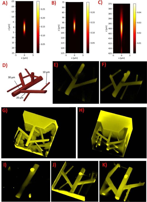
Biofabrication 13 (2021) 015016 https://doi.org/10.1088/1758-5090/abb063
Biofabrication
PAPER
On-chip high-definition bioprinting of microvascular structures
OPEN ACCESS
Agnes Dobos1,2, Franziska Gantner1,2, Marica Markovic1,2, Jasper Van Hoorick3,4, Liesbeth Tytgat3,4,
RECEIVED Sandra Van Vlierberghe3,4 and Aleksandr Ovsianikov1,2,5
11 February 2020
1
3D Printing and Biofabrication Group, Institute of Materials Science and Technology, Technische Universität Wien (TU Wien), Vienna,
REVISED
3 August 2020 Austria
2
Austrian Cluster for Tissue Regeneration (http://tissue-regeneration.at), Austria
ACCEPTED FOR PUBLICATION 3
18 August 2020 Polymer Chemistry and Biomaterials Group, Centre of Macromolecular Chemistry, Ghent University, Ghent, Belgium
4
Brussels Photonics, Department of Applied Physics and Photonics, Flanders Make and Vrije Universiteit Brussel, Brussels, Belgium
PUBLISHED 5
Author to whom any correspondence should be addressed.
12 December 2020
E-mail: Aleksandr.Ovsianikov@tuwien.ac.at
Original content from Keywords: multiphoton lithography, high-resolution bioprinting, thiol-ene chemistry, hydrogels, organ-on-chip, vascularization,
this work may be used
under the terms of the microfluidic
Creative Commons Supplementary material for this article is available online
Attribution 4.0 licence.
Any further distribution
of this work must
maintain attribution to Abstract
the author(s) and the title
of the work, journal ‘Organ-on-chip’ devices which integrate three-dimensional (3D) cell culture techniques with
citation and DOI.
microfluidic approaches have the capacity to overcome the limitations of classical 2D platforms.
Although several different strategies have been developed to improve the angiogenesis within
hydrogels, one of the main challenges in tissue engineering remains the lack of vascularization in
the fabricated 3D models. The present work focuses on the high-definition (HD) bioprinting of
microvascular structures directly on-chip using two-photon polymerization (2PP). 2PP is a
nonlinear process, where the near-infrared laser irradiation will only lead to the polymerization of
a very small volume pixel (voxel), allowing the fabrication of channels in the microvascular range
(10–30 µm in diameter). Additionally, 2PP not only enables the fabrication of sub-micrometer
resolution scaffolds but also allows the direct embedding of cells within the produced structure.
The accuracy of the 2PP printing parameters were optimized in order to achieve high-throughput
and HD production of microfluidic vessel-on-chip platforms. The spherical aberrations stemming
from the refractive index mismatch and the focusing depth inside the sample were simulated and
the effect of the voxel compensation as well as different printing modes were demonstrated.
Different layer spacings and their dependency on the applied laser power were compared both in
terms of accuracy and required printing time resulting in a 10-fold decrease in structuring time
while yielding well-defined channels of small diameters. Finally, the capacity of 2PP to create
vascular structures within a microfluidic chip was tested with two different settings, by direct
embedding of a co-culture of endothelial- and supporting cells during the printing process and by
creating a supporting, cell-containing vascular scaffold barrier where the endothelial cell spheroids
can be seeded afterwards. The functionality of the formed vessels was demonstrated with
immunostaining of vascular endothelial cadherin (VE-Cadherin) endothelial adhesion molecules
in both static and perfused culture.
1. Introduction provide more insights into the pathological and
physiological functions of tissues compared to 2D
Three-dimensional (3D) cell culture models that have cell cultures [1, 2]. ‘Organ-on-chip’ devices which
the capacity to recapitulate the biochemical func- integrate 3D cell culture techniques with micro-
tionalities, mechanical properties and the microar- fluidic approaches could deliver an important plat-
chitecture of organs have been gaining increasing form to further improve in vitro organ and disease
attention in biomedical research. These systems could models [3, 4].
© 2020 The Author(s). Published by IOP Publishing Ltd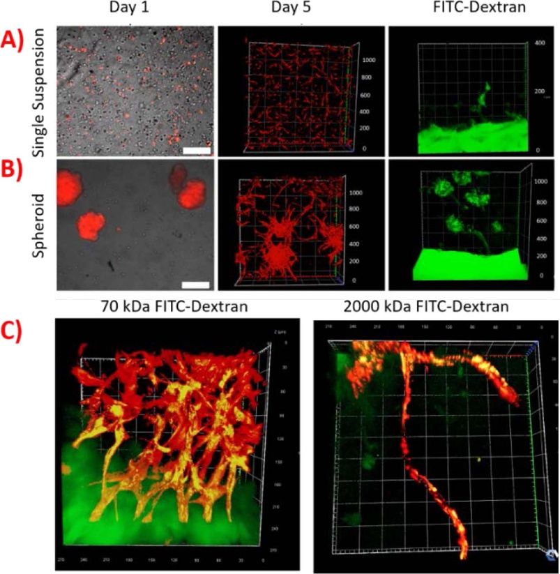
Biofabrication 13 (2021) 015016                                                                       A Dobos et al

     Several different polymers have been developed        supporting cell line co-cultured with endothelial cells
to home cells in 3D cell cultures, including nature-       also showed improved vascularization compared to
derived hydrogels and synthetic materials [2, 5, 6].       a monoculture of endothelial cells. Supporting cells
Natural hydrogels are physically or chemically cross-      can be primary cells or cell lines including fibro-
linked polymer networks which can take up large            blasts [27], hepatocytes [28], adipose derived stem
quantities of water without dissolving [6, 7]. They        cells [29], mesenchymal stem cells [30] or other cell
are often derived from the non-cellular compart-           types [31].
ment of the tissues called the extracellular mat-               There are several different ways how 3D vascu-
rix (ECM) [8]. Some of the commonly used ECM               lar structures could be created inside the microfluidic
derived hydrogels include collagen [9–12], gelatin         chips [32]. One of the most widespread approaches
[13–16] and hyaluronic acid [12, 17]. The advant-          are using a template (sacrificial) material, needles or
ages of such materials include good biocompatib-           rods during the channel production which could be
ility, biodegradability and they often possess cell-       removed at a later time point leaving a hollow chan-
responsive functionalities [5]. However, one of the        nel to be seeded with endothelial cells [33, 34].
main challenges in the use of such materials for                Bioprinting can provide a valuable toolset to
biofabrication purposes includes the lack of con-          engineer vascularized tissue and organ-on-chip
trol over the material properties due to the absence of    models [35]. These constructs can be fabricated using
(photo-)crosslinkable functional groups. Therefore,        two main tissue engineering approaches either using
several different approaches have been developed to        a scaffold-based [36, 37] or bottom-up (BU) tech-
introduce reactive groups including (meth)acryloyl         nology [38–40]. In scaffold-based bioprinting, cells
or thiol-ene functionalities to create networks fol-       are either seeded or embedded in a bioink matrix,
lowing a chain- or step-growth polymerization              while in BU bioprinting usually cell-spheroids are
[15]. Thiol-ene based step-growth polymerization           used without any scaffold support. Although these
offers several advantages over the more traditional        approaches can provide a promising strategy to form
chain-growth hydrogels, such as the lack of oxy-           neovascularized tissue models, they often lack the res-
gen inhibition and faster reaction kinetics enabling       olution to create channels in the microvascular range
the reproducible production of 3D printed struc-           (under 30 µm).
tures with high structural integrity at low light               To circumvent this drawback, high resolution
intensities [18].                                          additive manufacturing techniques including two-
     Although many different strategies have been          photon polymerization (2PP) can be applied. 2PP
developed to create biomimetic cell environments,          is a nonlinear process where a near-infrared laser
one of the main challenges in tissue engineering and       pulse is absorbed by a photosensitive material. In
organ-on-chip devices remains the lack of vascular-        this respect, polymerization will only occur in the
ization in the fabricated 3D models [19, 20]. The          area where the photon density is high enough to
vast majority of tissues in the body depend on blood       result in simultaneous absorption of two or more
vessels to supply nutrients and oxygen to the cells        photons, each carrying part of the required energy
as the diffusion limit for oxygen is approximately         to pass the band gap [40, 41]. As a consequence, this
100–200 µm [21]. Microcirculation, based on the            method does not require layer-by-layer deposition of
microvasculature, is the distal functional unit of the     the material and the structures can be written directly
vascular system. The microvascular system consists of      within the volume of the sample. Additionally, by
vessels with different diameters including the arteri-     controlling the light dose, resolution under the dif-
oles (± 30 µm), venules (± 20 µm) and capillaries          fraction limit can be achieved by polymerizing a small
(< 8 µm) [22, 23]. Capillaries and venules are formed      volume pixel (voxel). Furthermore, photopolymeriz-
only by endothelial cells while arterioles also contain    ation can proceed under relatively mild reaction con-
an additional layer of smooth muscle cells [23]. Tis-      ditions, enabling the direct embedding of cells within
sues larger than a few hundred micrometres require         the bioink [42]. The accuracy of the 2PP produced
the formation of new blood vessels by vasculogenesis       structures mainly depends on the voxels and their
and/or angiogenesis to supply the metabolic needs of       arrangement [43].
the cells. Vasculogenesis is by definition the differen-        The present work focuses on 2PP of microvas-
tiation of a stem cell, precursor or angioblast while      cular structures directly on-chip using a thiol-ene
angiogenesis describes the process of remodelling and      photo-click hydrogel consisting of thiolated gelatin
expansion where new vessels sprout from the already        (Gel-SH) and gelatin-norbornene (Gel-NB). In
existing ones [24].                                        order to demonstrate the ability of the employed
     There are multiple different approaches which         material to support the spontaneous formation of
have been developed to increase the vasculariza-           vascular structures, a UV-induced (single-photon)
tion of a tissue construct. Previous studies showed        encapsulation co-culture of human umbilical vein
that the scaffold design including the provided pore       endothelial cells (HUVEC) with adipose derived stem
size and degradability is crucial for the formation        cells (ASC/TERT1) was performed. This setting also
of a neovascular network [25, 26]. The use of a            allows to address the network forming capacity of the

                                              2
Biofabrication 13 (2021) 015016                                                                       A Dobos et al

HUVECs spheroids compared to single cell suspen-          pulse duration of 70 fs after the microscope object-
sions. In order to direct the alignment of HUVECs         ive (Plan-Apochromat, 10x/0.4, Olympus, Tokyo,
into vascular structures with various diameters           Japan) and a repetition rate of 80 MHz was
resembling the diameters of the natural microvascu-       employed. The used setup is described elsewhere
lature, gelatin-based microvascular units were struc-     [18]. All experiments were performed at a cent-
tured in the same material using 2PP. The accuracy        ral wavelength of 720–725 nm and with a writing
of the 2PP printing can be affected by spherical aber-    speed of 1000 mm s−1 and line spacing of 0.5 µm
rations resulting from refractive index (RI) mismatch     [44]. To compensate for the RI mismatch of the
and focusing depth. The printing parameters were          immersion medium and the fabrication material
optimized to increase the throughput and precision        the layer spacing was multiplied with the correction
of the system accounting for voxel size and different     factor (c)
printing modes. To further demonstrate the capabil-
                                                                                       ni
ities of this technology, two different approaches were                           c=
                                                                                       nm
explored: direct encapsulation of HUVECs spheroids
into single microvascular units surrounded by the         with ni being the RI of the immersion medium and
supporting cells, and the seeding of the endothelial      nm the RI of the material.
cell spheroids into a microvascular barrier structure
containing only the supporting cell line. The cell        2.3. Methylcellulose preparation
alignment was followed over 5 days via laser scanning     Methyl cellulose was sterilized by autoclaving before
confocal microscopy (LSM) in static and perfused          the addition of preheated EGM-2 medium at 60 ◦ C
culture and finally, the intercellular junctions were     in the concentration of 1.2 w v−1 %. The solution
immuno-stained using an anti-vascular endothelial         was stirred with a magnetic stirrer for 20–30 min at
(VE)-Cadherin stain.                                      room temperature, then for 2 h at 4 ◦ C. Afterwards,
                                                          the solution was centrifuged for 2 h at 5000 g at 4 ◦ C.
2. Materials and methods                                  The supernatant was transferred to a new falcon tube
                                                          and stored at 4 ◦ C. For further application, a 20 V%
All chemicals, unless stated otherwise, were pur-         methyl cellulose solution in EGM-2 containing 5%
chased from Sigma-Aldrich (Saint Luis, USA). The          FBS was used.
images were captured using a laser-scanning confocal
microscope (LSM 800 Airyscan, Zeiss, Oberkochen,          2.4. Cell spheroid formation
Germany).                                                 Microtissues 3D Petri Dish 81-well micro-moulds
                                                          were used to form endothelial spheroids. 1 wt %
                                                          agarose solution was prepared in sterile water and
2.1. Cell culture                                         heated until it dissolved. Once it dissolved, the micro-
ASC/TERT1 adipose derived stem cells and green            tissue moulds were filled up with agarose and left
fluorescent protein (GFP) labelled ASC/TERT1 cells        until it solidified. Afterwards, the agarose moulds
(ASC-GFP) (Evercyte, Vienna, Austria) were cul-           were equilibrated in phosphate buffered saline (PBS)
tured in EGM-2 cell culture medium (Lonza Group           for at least 2 h in 12-well plates (Greiner-Bio,
AP, Basel, Switzerland) supplemented with an addi-        Kremsmünster, Austria). RFP-HUVECs were trypsin-
tional 8% foetal bovine serum (FBS) to achieve            ized with 0.05% Trypsin-EDTA to detach and cent-
10% final concentration of FBS. HUVEC labelled            rifuged for 5 min at 170 g before resuspending it in
with red fluorescent protein (RFP-HUVEC) (PeloBi-         20% methylcellulose solution at a concentration of
otech GmbH, Plantegg, Germany) were maintained            8.1 × 10⁴ cells per 300 µL. 300 µL of cell solution
in EGM-2 cell culture medium supplemented with            was pipetted on top of each agarose mould and left
an additional 3% FBS to have a final concentration        to sediment for at least 15 min before the addition
of 5%. All cell culture plastic flasks used for RFP-      of 2 ml of 20% methylcellulose solution in cell cul-
HUVECs were coated with quick coating solution            ture media. Spheroids were formed and used after
(PeloBiotech GmbH) for 15 min before the seeding          24 h. ASC-GFP spheroids were prepared using the
of cells. The cells were sustained at 37 ◦ C and 5%       same protocol without the addition of 20% methyl
CO2 incubator. When cells reached 90% confluency,         cellulose solution to their corresponding cell culture
0.05% Trypsin-EDTA was added for 3 min to detach          media.
the cells. The cells were then diluted with fresh cell
culture media and placed in T75 flasks (Greiner Bio-      2.5. Synthesis of gel-NB and gel-SH
1, Kremsmünster, Austria). RFP-HUVECs were used           The synthesis of Gel-NB was performed via reac-
between passage 4 and 10.                                 tion of 5-norbornene-2-carboxylic acid with the
                                                          primary amines of gelatin type B (kindly sup-
2.2. Two-photon polymerization (2PP) setup                plied by Rousselot, Ghent, Belgium) using EDC
A tuneable femtosecond near infrared (NIR) laser          (1–ethyl–3–(3–dimethylaminopropyl)carbodiimide;
(MaiTai eHP DeepSee, Spectra-Physics) with a              NHS (n-hydroxysuccinimide; Acros, Geel, Belgium)

                                             3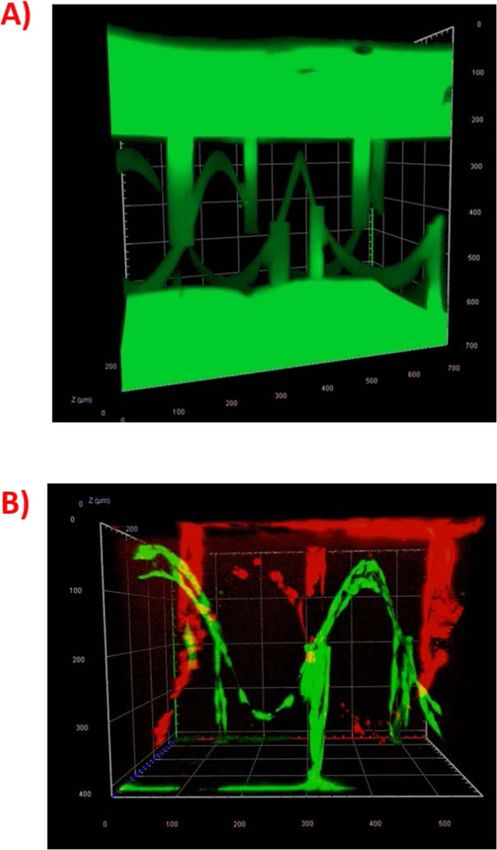
Biofabrication 13 (2021) 015016                                                                          A Dobos et al

coupling chemistry according to a previously repor-       2.9. Voxel simulation
ted protocol yielding a degree of substitution (DS)       Due to the nonlinear nature of 2PP, considera-
of 90%. The Gel-SH was prepared via reaction of           tions regarding the shape and size of the voxel can
the primary amines with D,L-N-acetylhomocysteine          be done with the help of the squared illumination
thiolactone yielding a DS of 63% [13, 45].                point spread function, IPSF2 (x,y,z) , which describes
                                                          the intensity distribution around the focus [47]. To
                                                          simulate the point-spread function IPSF2 for 2PP,
2.6. Functionalization of the high precision glass        the IPSF which describes one-photon absorption
slides                                                    was first calculated with PSFLab [48]. The simula-
In order to improve the adhesion of the produced          tions were done in the xz-plane for an air object-
hydrogel structures on the chip, the 170 µm thick         ive (n1 = 1) with a numerical aperture (NA) of 0.4
glass coverslips (IBIDI GmbH, Martinsried, Ger-           illuminated with a Gaussian beam propagating in
many) were functionalised. To this end, they were         z-direction with light polarized along the x direc-
plasma cleaned for 10 min. Subsequently, 10 vol % of      tion at a wavelength (λ) of 720 nm with a filling
(3-mercaptopropyl)trimethoxysilane was mixed with         factor (ßG ) of 1. The coverslip was 170 µm thick with
85.5% ethanol and 4.5% deionized water and the            a RI of 1.52 (n2 ). The simulated sample had a RI
plasma cleaned coverslips were submerged for 3 h at       of 1.346 (n3 ) for unpolymerized material and 1.356
room temperature. Afterwards, the glass slides were       for polymerized one based on a RI measurement
washed three times with ethanol on both sides and         on UV-crosslinked and precursor material using a
were dried under nitrogen gas. Finally, they were         refractometer (Zeiss, Oberkochen, Germany) The
placed in a heating chamber at 110 ◦ C for 10 min.        IPSF2 was simulated for three different depths in the
All functionalized coverslips were stored in ethanol      material.
until use.                                                    The full width half maximum (FWHM ) of the
                                                          IPSF2 was calculated with the values of the IPSF from
2.7. UV-induced cell encapsulation                        the PSFLab simulations based on the FWHM of a
Gel-SH and Gel-NB based hydrogels were prepared           gaussian function with
by dissolving them in phosphate buffered saline (PBS)                                       1
in a 37 ◦ C water bath. Once dissolved, the two                       FWHMIPSF2 = FWHMIPSF √
                                                                                             2
components were mixed to achieve a final concen-
tration of 5 wt% at an equimolar thiol/ene ratio.             To calculate the intensity in the focal plane (I peak ),
For the single cell suspension sample, RFP-HUVECs         the laser pulse was assumed to be sech2 (squared
were trypsinized and resuspended in a final concen-       hyperbolic secant) shaped and the peak intensity was
tration of 8.1 × 10⁵ cells per ml together with a         calculated with gaussian beam approximations using
single suspension of ASC/TERT1 cell at a 1:1 ratio        [49]
in respect of the cell number. The cell suspension                                        Pπ(NA)
                                                                                                    2

was added to the hydrogel precursor solution together                      Ipeak = 0.88
                                                                                           Rτp λ2
with 0.3 mM Li-TPO photoinitiator [46] and 30 µl of
the hydrogel-precursor mixture was pipetted on func-      With the average laser power (P), the NA of the
tionalized glass bottom dishes (IBIDI, GmbH) fol-         objective, repetition rate (R) and the pulse duration
lowed by UV irradiation at 365 nm at 1 J (Boekel Sci-     (τ p ).
entific UV Crosslinker AH, USA). For the spheroid
experiments, RFP-HUVEC spheroids were removed             2.10. CAD-CAM mimicry quantification
from the agarose mould and mixed with a single            The thiol-ene gelatin hydrogel was prepared by sep-
cell suspension of ASC/TERT1 cells in the above-          arately dissolving Gel-SH and Gel-NB in PBS at
mentioned concentration together with the hydrogel        37 ◦ C. Once dissolved, the two components were
precursors and 0.3 mM Li-TPO followed by UV irra-         mixed to achieve a final gelatin concentration of
diation as described above. Finally, EGM-2 with 5%        7.5 wt % (1:1 thiol-ene ratio) and supplemen-
FCS cell culture medium was added to the hydrogel         ted with 0.5 mM biocompatible diazosulphonate
pellets. The hydrogel pellets were imaged for 5 days      two-photon photoinitiator (DAS) [42]. For phys-
using LSM.                                                ical gelation, the samples were incubated at 8 ◦ C
                                                          for 15 min prior to printing. To quantify the aber-
                                                          rations, 500 µm x 500 µm x 500 µm cubes con-
2.8. Dextran-FITC perfusion                               taining 30 µm rectangular channels at different
After 5 days, the cell containing hydrogels were cut in   heights were produced with the previously mentioned
half with a scalpel and 0.5 mg ml−1 70 and 2000 kDa       setup (figure 1(A)). After structuring, the residual
dextran-FITC (TdB Consultancy, Uppsala, Sweden)           material was removed by washing with warm PBS
dissolved in cell culture media was added. The diffu-     (37 ◦ C) followed by overnight incubation at 37 ◦ C to
sion of the dextran was recorded using LSM 800 after      reach equilibrium swelling. The next day, the struc-
1 h of incubation at 37 ◦ C (figure S1).                  tures were incubated in PBS containing 2000 kDa

                                             4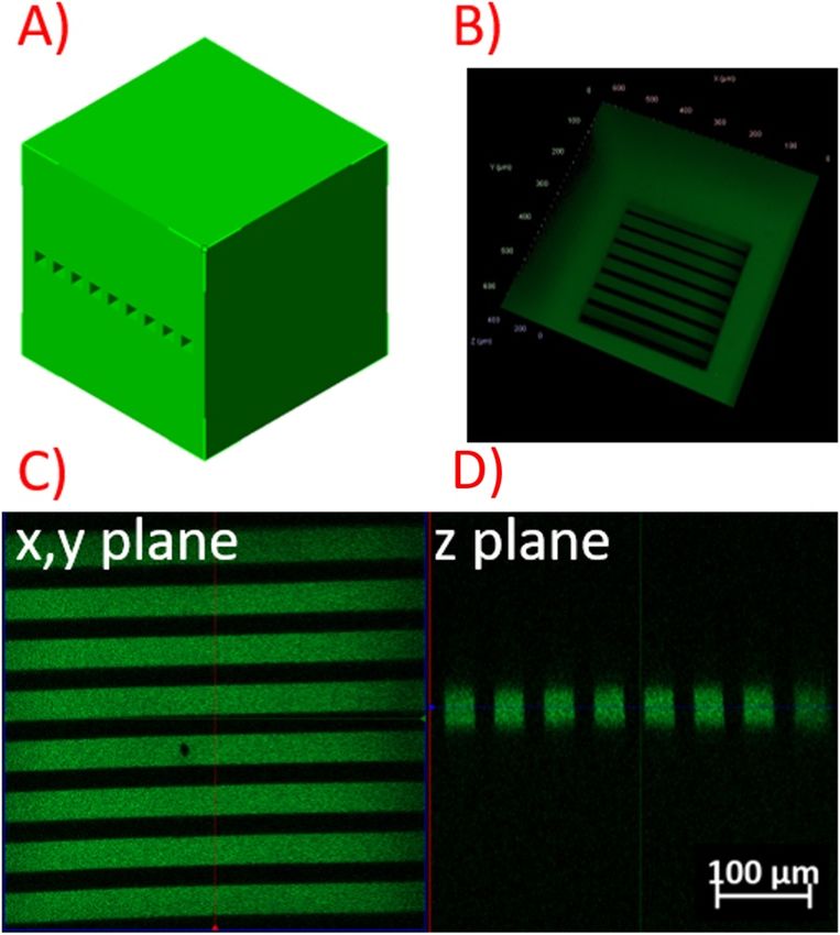
Biofabrication 13 (2021) 015016                                                                                     A Dobos et al

   Figure 1. Quantitative measurement of CAD-CAM mimicry. (A) Representative CAD design of a single channel construct. (B)
   HD bioprinted design where the channels were filled with 2000 kDa FITC-dextran (C-D) The 2D images of the channels used for
   analysis at xy and z plane.

FITC-dextran and the diameter of the channels was                 2.12. Immunostaining
imaged using LSM 800 (figure 1(B)). The images                    At different time points after printing, the constructs
were analyzed using ImageJ and the channel dia-                   were washed with PBS and fixed for 2 h with 4% His-
meters in xy and z plane direction were compared                  tofix (Carl Roth GmbH, Karlsruhe, Germany). After-
to the diameters of the designed CAD described in                 wards, the fixed structures were washed with PBS and
figures 1(C)–(D).                                                 permeabilized with 0.5% Triton-X in PBS for 10 min.
                                                                  The non-specific absorption of the antibodies was
                                                                  blocked by incubation in 1 wt% bovine serum albu-
                                                                  min in PBS (PBS-BSA) for 15 min before the addi-
2.11. High-definition (HD) bioprinting of                         tion of anti-VE Cadherin antibodies (Thermo-Fisher,
cell-containing constructs                                        Waltham, MA, USA) in a 1:500 dilution for 2 h at
After functionalization of the glass coverslips, a self-          room temperature. Afterwards, the constructs were
adhesive 6 channel slide (sticky-Slide VI 0.4, IBIDI              washed for 15 min with PBS-BSA before the addi-
GmbH, Germany) was mounted on the glass slide and                 tion of the Goat anti-Rabbit IgG Superclonal Sec-
was used immediately. The thiol-ene gelatin hydro-                ondary Antibody, Alexa Fluor 488 (Thermo-Fisher,
gel was prepared by separately dissolving Gel-SH and              Waltham, MA, USA) in a dilution of 1:1000 for
Gel-NB in PBS at 37 ◦ C. Once dissolved, the two com-             2 h. Next, the structures were washed again for
ponents were mixed to achieve a final gelatin concen-             15 min with PBS-BSA before the addition of Hoechst
tration of 7.5 wt% (1:1 thiol-ene ratio). The spher-              34 850 (Invitrogen, Carlsbad, CA, USA) in a dilu-
oids and the supporting cells were added based on                 tion of 1:100 in PBS-BSA for 1 h. The cells were
the above described protocol. Finally, 0.5 mM DAS                 imaged using LSM 800.
was added and the bioink was pipetted on the chip
(approximately 30 µl). After printing, EGM-2 with                 2.13. HD bioprinting of intertwining spiral
5% FBS cell culture media was added to the ves-                   network
sel constructs and the unpolymerized material was                 The thiol-ene gelatin hydrogel was prepared and
removed. Two days after printing, the samples were                2PP-processed using the protocol described above.
perfused with cell culture medium using a syringe                 The produced structures were washed and developed
pump (PHD Ultra, Harvard Apparatus, Cambridge,                    using EGM-2 medium supplemented with 5% FCS
MA, USA) at a flow rate of 5 µl min−1 for an addi-                and left to reach equilibrium swelling at 37◦ C.
tional 3 days before fixing the cells.                            The RFP-HUVEC and ASC-GFP spheroids were

                                                    5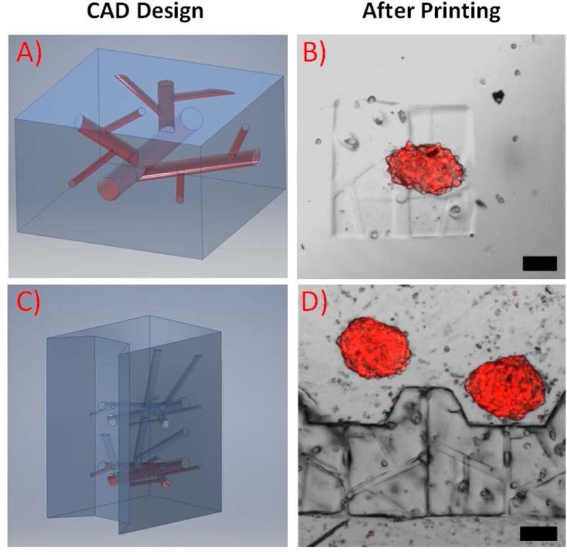
Biofabrication 13 (2021) 015016                                                                                         A Dobos et al

   Figure 2. UV encapsulation of RFP-HUVEC and ASC/TERT1 cells in 5% Gel-SH and Gel-NB hydrogels. (A) Single cell
   suspension of RFP-HUVECs and unlabelled ASC/TERT cells encapsulated at 1:1 ratio. The red fluorescent protein label allows the
   direct imaging of the cells without the need of further staining, while the ASC/TERT1 supporting cell line is only visible under
   bright field microscopy. After day 5, the RFP-HUVECs shows extended morphology, although the cells stayed separated without
   the formation of a preliminary network. Upon incubation with 2000 kDa dextran-FITC after 5 days the dye was only able to
   diffuse into the hydrogel up to 100 µm after 1 h. (B) RFP-HUVECs spheroid co-culture with ASC/TERT1 supporting cells. After
   UV-induced encapsulation, the spheroids showed a round morphology. However, after 5 days, the cells started to sprout from the
   spheroid towards each other showing a higher degree of interconnection within the hydrogel. When incubating with 2000 kDa
   dextran-FITC, the dye was able to penetrate the hydrogel fully after 1 h. (C) Co-localization of the FITC-dextran with
   RFP-HUVEC spheroid networks using 70 kDa and 2000 kDa dextran after 5 days.

removed from the mould by pipetting and were drop-                  5 wt% Gel-NB-Gel-SH hydrogels at an equimolar thi-
seeded at the opposite sides of the chip. The system                ol/ene ratio in the presence of 0.3 mM UV photoini-
was monitored for 5 days using LSM 800.                             tiator (i.e. Li-TPO) and the supporting cells. After
                                                                    UV encapsulation, the cells were imaged at different
3. Results and discussion                                           time points using LSM. Due to the red fluorescent
                                                                    label, the RFP-HUVECs are visible without staining,
3.1. UV embedding of RFP-HUVECs with                                while the supporting cells are not interfering with the
supporting cells in thiol-ene hydrogel                              imaging of the network. In both cases, the thiol-ene
Thiol-ene photo-click gelatin hydrogels already                     photo-click Gel-NB-Gel-SH showed good biocom-
showed remarkably high processability, biocompat-                   patibility and supported cell survival and adhesion.
ibility and supported the adhesion and proliferation                Although the cells were characterized by a uniform
of cells when used as a bioink for HD bioprint-                     cell distribution and good cell viability immedi-
ing [18]. In order to assess the capacity of RFP-                   ately after encapsulation, the single cell suspension
HUVEC to form preliminary vascular networks in                      did not show any sign of interconnection between
a Gel-NB-Gel-SH hydrogel, the cells were first encap-               the cells after 5 days despite the fact that the cells
sulated via UV-induced crosslinking. To this end,                   exhibited an elongated morphology. Previous studies
(ASC/TERT1) were used in a 1:1 ratio to the HUVECs                  have employed fluorescently labelled dextran (FITC-
as supporting cells.                                                dextran) to evaluate the permeability of the prelim-
     Previous studies have highlighted the importance               inary vascular networks [51, 52]. When the diffusion
of high initial cell loading and cell-cell contact for              of different sized dextran molecules was monitored
vascularization [50]. Therefore, two different settings,            on a monolayer of HUVECs using a transwell setup,
namely a single cell suspension and a spheroid culture              the diffusion decreased with increasing molar mass,
of RFP-HUVECs were compared to investigate the                      where the 2000 kDa dextran resulted in a diffusion
influence of spheroid culture on network formation.                 rate close to zero after 2 h [53]. Since this high molar
The spheroids were obtained overnight after seed-                   mass FITC-dextran is unable to diffuse into the bulk
ing the cells onto non-adhesive agarose moulds and                  hydrogel, we hypothesize that it can only be detected
were encapsulated via UV-induced encapsulation in                   across the matrix if a preliminary HUVECs aligned

                                                      6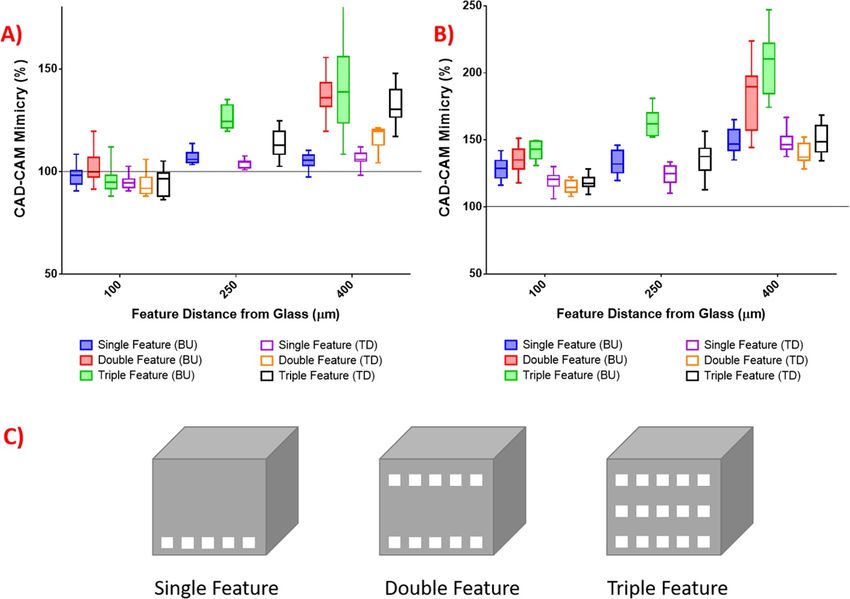
Biofabrication 13 (2021) 015016                                                                             A Dobos et al

network is present, while the lower molecular weight       Table 1. FWHM for x and z (beam propagation)-direction of the
                                                           simulated IPSF2 at different depths in the material.
FITC-dextran (70 kDa) which can also diffuse into
the bulk of the hydrogel will also be traced within        Depth [µm]           FWHMx,y[µm]              FWHMz [µm]
the capillaries which will be faster compared to the
                                                           0                    0.731                    7.628
passive diffusion. Therefore, after 5 days, the hydro-     100                  0.734                    7.856
gel pellets containing cells were incubated with 2000      400                  0.903                    14.949
kDa dextran-FITC for 1 h to address the permeabil-
ity of the system. After 1 h, the signal of the FITC-
dextran could only be detected up to 100 µm from the       voxel during structuring was modelled using PSFlab
edge of the hydrogel pellet (figure 2(A)). The spher-      with a custom-made algorithm. Figures 3(A)–(C)
oid co-culture however, presented a higher degree of       shows the simulation of the squared illumina-
sprouting after 5 days of co-culture with ASC/TERT1        tion point-spread function (IPSF2 ) at different
cells. These cells exhibited an extended morphology        focusing depths. When structuring deeper into the
as well. After incubation with the 2000 kDa dextran-       material, the FWHM (table 1) increases, show-
FITC dye, it was possible to trace the fluorescence        ing a larger focus area which results in a lower
all across the hydrogel pellet after 1 h in which          peak intensity and photon density in the focal area.
the FITC dextran showed co-localization with the           These parameters could impact the accuracy of HD
HUVECs (figures 2(B)–(C)). Additionally, 70 kDa            bioprinted structures leading to poor CAD-CAM
FITC-dextran, which can freely diffuse into the            mimicry.
hydrogel, can be further along the network formed by            During 2PP, the structures are formed by stack-
HUVECs compared to the passive diffusion into the          ing of the voxels, therefore, their optimal arrange-
hydrogel (figure 2(C)).                                    ment is crucial for introducing high resolution fea-
                                                           tures. The calculated voxel height of our setup at a
3.2. Printing parameter optimization of small              depth between 0 and 100 µm is around 8 µm (table 1)
diameter channels                                          when using a gelatin hydrogel (RI of unpolymerized
In order to fabricate reproducible organ- or tissue-       material is approximately: 1.34, NA of the objective:
on-chip models, having only randomly distributed           0.4, structuring wavelength: 720 nm), and supposing
microvascular network is often not satisfactory, as a      that the polymerized voxel corresponds to its FWHM.
precise positioning of the vascular network is also        Although the influence of spherical aberrations on
desired. However, most of the available biofabrica-        voxel height is negligible in smaller objects, it is
tion methods do not offer the resolution which allows      more pronounced in higher structures as described in
the production of such small diameter round and            table 1. The simulated voxel height only shows a slight
branching channels [54, 55]. The accuracy of HD            variation between focussing of the laser into poly-
bioprinting depends on several different parameters        merized or un-polymerized material (table S1 avail-
which could be of crucial importance when produ-           able online at stacks.iop.org/BF/13/015016/mmedia).
cing these structures.                                     In order to provide a flexible possibility to account
    Especially important in this respect is to take        for variable voxel heights, a voxel compensation
into account the dimensions of the polymerized voxel       feature was introduced in the system control soft-
during the printing process. The shape of the voxel        ware. This feature allows the calculation of the laser
resembles a spinning ellipsoid with the z axis being       irradiation path considering voxel height and the
larger than the x and y planes. The size of the voxel is   ratio in which the voxel would overlap with the
dependent on the NA of the objective, the RI of the        designed channel. Once the object is sliced and over-
material and the applied wavelength (λ) as described       lap is detected, the voxel is left out during the printing
by equation(1) for the full width at half maximum          process. For testing this printing mode, a cube con-
(FWHM) of the voxel intensity in the x,y-plane and         taining several different sized round channels with
equation(2) for the z-plane [47].                          diameters ranging from 10 to 30 µm was designed
                                                           (figure 3(D)). This structure was either produced
                                                           without setting the voxel height or overlap features
                         0.32λ √
               FWHMx,y = √     2 ln 2               (1)    (figure 3(E)) or with a voxel compensation of 8 µm
                           2NA                             (figure 3(F)). As the smallest feature size of the
                                                           designed CAD is almost the same size as the voxel
                                                           itself (10 µm), and every voxel which overlaps the
               [               ]                           channel by 0.2 was left out when processing the
        0.532λ         1          √
 FWHMz = √           √           2 ln2 (2)                 material. By adding this factor alone, it was possible
            2    RI − RI − NA
                         2   2
                                                           to produce accurate channels within the 180 µm high
                                                           cube.
    The deeper the laser is focused in the material             Previous studies have shown that the surface
after the coverglass, the more spherical aberrations       roughness and accuracy of the 2PP structures are
affect the voxel shape. The spherical aberration of the    highly dependent on the voxel overlap settings (layer

                                              7
Biofabrication 13 (2021) 015016 A Dobos et al
Figure 3. The accuracy and optimization of produced HD bioprinted small channelled structures. (A)–(C) Simulation of the
IPSF2 in the x,z plane at 720 nm. The IPSF2 was simulated for three different positions in the material to show its distortion for
increased structuring depths leading to a larger voxel. (A) IPSF2 at the interface between coverslip and sample material at (B)
100 µm and (C) 400 µm depth in the sample material. (D)–(F) The effect of voxel compensation of the channelled structures of
180 µm height. (D) The designed CAD model containing branching round channels with different diameters ranging from
10–30 µm. (E) Structure produced without voxel compensation (F) with compensation for an 8 µm long voxel. (G)-(H)
Optimization of structures with a height of 420 µm. (G) Structures produced bottom-up (BU), starting from the glass coverslip
and (H) same structures produced top-down starting from the top of the microfluidic chip. (I)-(K) The effect of different layer
spacing on the accuracy of the produced structure using 70 mW laser power and a voxel height of 8 µm (I) with a layer spacing of
0.5 µm (J) layer spacing of 3 µm (K) layer spacing of 9 µm.
spacing, dz) [43]. By increasing the overlap, surface setting, the previously mentioned cubes with differ-
roughness decreases thereby allowing the printing of ent sized channels (figure 3) were produced at dif-
well-defined features, however in turn it increases the ferent powers (45 mW, 70 mW and 100 mW) with
structuring time. By increasing the laser power, the an increasing layer spacing from 0.5 µm to 13 µm
voxel size also increases in all dimensions [56]. In using the previously described voxel intersection
order to test the power dependency of the overlap printing mode settings. The ability to perfuse the
8Biofabrication 13 (2021) 015016 A Dobos et al
Figure 4. The reproducibility of channeled structures using different printing modes at XY and Z planes at different heights. (A)
CAD-CAM mimicry at the XY plane using top-down and bottom-up printing modes. (B) CAD-CAM mimicry at the Z plane
using top-down and bottom-up printing modes. (C) CAD-designs of channeled structures.
produced channels was set as a quality threshold in Table 2. Average powers, peak intensities, intensities at FWHMz
and threshold layer spacings allowing the production of open
regard of over-polymerization and mechanical sta- channels at different power settings.
bility. Table 2 shows the used average powers (Pavg )
with calculated peak intensities (Ipeak ) and the layer Pavg [mW] 45 70 100
spacing (dzth ) at which the channels were first per- I peak [GW cm−2 ] 685.67 1066.59 1523.70
fusable (not over-polymerized). Since the area within I FWHM [GW cm−2 ] 342.83 533.30 761.85
the FWHM is mainly contributing to induce 2PP, the dzth [µm] 1.5 3 7
simulated FWHMz value at 100 µm depth at which
the intensity has fallen to half of its value, was used as
reference value. For a peak intensity of 686 GW cm−2 , 0.5 µm, figure 3(J) at 3 µm and figure 3(K) at 9 µm
z-distances between the voxels that were smaller overlap. By choosing the optimal layer spacing, the
than 25% of the FWHMz led to over-polymerization structuring time was reduced by 10-fold compared to
within the material, resulting in closed channels. Sim- previously reported protocols [18, 42]. With a layer
ilar result was also observed at peak intensities of spacing of 0.5 µm, the CAD depicted in figure 3(D)
1067 GW cm−2 and 1524 GW cm−2 for layer spa- takes over 9 min to print, while when using a
cings of less than 38% and 89% of the FWHMz. When layer spacing of 5 µm, the same design takes less
choosing small layer spacings, the number of voxels than 50 s while maintaining the round shape and
that overlap is increased and the structuring area is accuracy of the channel.
illuminated more often with the highly effective area Several previous studies indicated that forming a
around the focal spot, generating a higher number physical gel before processing can improve the mech-
of radicals. Further, when structuring with smaller anical stability and influence the properties of gelatin-
layer spacing, it is possible that parts of the voxel based hydrogels [15, 57, 58]. This phenomenon is
reach into the channels. We hypothesize that these attributed to an improved crosslinking efficiency, as
two effects lead to over-polymerization of the mater- upon physical gelation interchain hydrogen bonds
ial within the channels. When increasing the intensity, are formed in the gelatin backbone, leading to semi-
the voxel size is increased and so is the overlap region, crystalline junction zones which can be partially
which makes it necessary to increase the layer spacing. locked by covalent crosslinks, possibly resulting in
Figure 3(I) shows an example of over-polymerization closer proximity between crosslinkable groups [15,
at 70 mW with different layer spacings which is 58]. Additionally, even a small difference between
visualized in figures 3(I)–(K) with figure 3(I) at the RI of the (glass) substrate and the material can
9Biofabrication 13 (2021) 015016 A Dobos et al
Figure 5. The two different chip setups tested for the vascular network formation of RFP-HUVECs. (A) CAD design of a single
unit vessel with a height of 180 µm. (B) The produced structure, where both the supporting cells and the RFP-HUVECs were
embedded in the hydrogel. (C) CAD design of a vessel barrier with a height of 400 µm. (D) Only the supporting cells were
embedded during HD Biopriting and spheroids were added after developing the structure. The scale bars represent 100 µm.
lead to spherical aberrations which is mainly depend- In order to test the effect of different printing
ent on the difference in the refractive indices and modes on samples with multiple features, similar
the focusing depth [59]. In turn, these aberrations cubes containing multiple sets of channels at dif-
change the irradiation conditions and therefore lead ferent heights were tested, where the double feature
to an inhomogeneous 2PP structuring at different ones had a set of channels at 100 and 400 µm and
sample depths. During 2PP from the cover glass into triple feature samples at 100, 250 and 400 µm. Com-
the material (BU), the objective has to focus through pared to BU mode, the TD mode consistently leads
multiple interfaces of already polymerized material to better CAD-CAM mimicry by avoiding focus-
with different RI’s leading to additional scattering of sing through the non-uniform material containing
the light and further spherical aberrations, which in 2PP structures already produced at different heights
turn can result in a mechanically weaker and distor- (figure 4). Close to the glass coverslip, the different
ted structure. Therefore, two different 2PP modes, BU printing modes did not show any significant differ-
and top-down (starting from the top of the structure, ences independently of the number of features intro-
TD) were tested. duced to the structure. However, when the BU mode
In order to quantify the effect of physical pre- was employed, the spherical aberration was more pro-
gelation and 2PP mode on the structuring integrity nounced the deeper into the material the objective
of produced constructs, 500 µm tall cubes contain- was focussed. The CAD-CAM mimicry has further
ing channels with a diameter of 30 µm were pro- deteriorated when more features were introduced
duced TD and BU both in a physically gelled and to the cube, while this effect was less significant in
non-gelled state using the previously established voxel the case of TD printing both in XY (figures 4(A))
intersection mode with a layer spacing of 5 µm. and Z plane (figure 4(B)). Finally, double featured
The cubes contained channels at different heights, channels for vascular structures were produced and
either at 100 µm, 250 µm or 400 µm. Once the the results indicated that by printing top-down, the
produced structures were developed and swollen accuracy of the structures can indeed be improved
overnight, the diameters of the channels were meas- (figure 3(H)) when compared to a BU approach
ured using Image J at both xy and in z planes and the (figure 3(G)).
CAD-CAM mimicry was plotted. Our results indicate
that physical gelation does improve the reproducib- 3.3. HD bioprinting of microcirculation-on-a-chip
ility of the channels but it does not significantly constructs
differ from the non-gelled samples for both print- After optimization of the 2PP parameters of small
ing modes (figure S2(A) and figure S2(B)) possibly channelled structures on chip, two different setups
due to the high viscosity of the hydrogel at room were created to test the vascular network formation
temperature. of RFP-HUVECs. In the first setup, the single unit
10Biofabrication 13 (2021) 015016 A Dobos et al
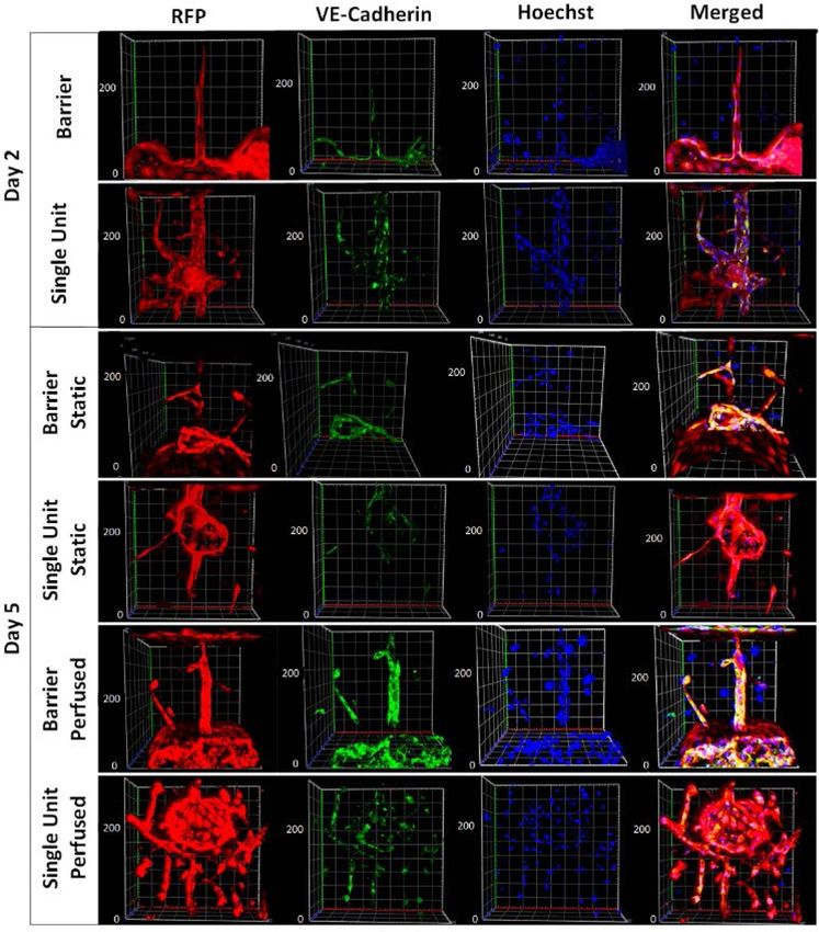
Figure 6. Immunostaining of vascular structures under different culturing conditions. The endothelial cells are visible via the red
fluorescent protein label (RFP). The cells showed extended morphology even after 2 days post-printing. The endothelial vascular
cadherin (VE-Cadherin) staining showed intercellular junction formation in all examined samples, however after 5 days, it was
more pronounced at the perfused culture compared to the static samples. The cell nucleus was stained with Hoechst 34 850,
showing a higher number of cells in the perfused culture compared to the static ones.
vessels (figure 5(A)), were produced by embedding of 400 µm were produced across the whole micro-
both the supporting cells (ASC/TERT1) and the fluidic channel thereby creating a barrier struc-
RFP-HUVECs in the bioink containing 7.5 wt% ture using the previously mentioned bioink for-
of the Gel-NB-Gel-SH hydrogel crosslinked with mulation (figure 5(C)). In this case, only the sup-
0.5 mM DAS photo-initiator. During the 2PP pro- porting cells were embedded in the structure dur-
cess, a cube with a height of 180 µm and an ing the HD bioprinting process, as the spher-
internal channel structure was fabricated around oids in the bioink are randomly distributed. Con-
the spheroid, positioning it in close proximity to sequently, positioning them close to the channels
the channels (figure 5(B)). Based on the previous is not possible during the process. However, once
experiments, the 2PP parameters were set at a laser the produced structure was developed by wash-
power of 70 mW and a layer spacing of 5 µm ing away the unpolymerized material, the RFP-
using the voxel intersection mode. In the second HUVECs spheroids were drop-seeded to the cre-
setting, cubes with internal channels with a height ated barrier, thereby allowing the migration of
11Biofabrication 13 (2021) 015016 A Dobos et al
Figure 7. Intertwined spiral channels. (A) Produced sample perfused with 2000 kDa FITC-Dextran (B) ASC-GFP cell spheroids
(green) and RFP-HUVECs entering the channels from two separate compartments after 5 days of culture.
the endothelial cells into the produced channels the formation of intercellular junctions between the
(figure 5(D)). endothelial cells, which are crucial to control the dif-
Previous studies have shown that HUVECs are fusion and transport of molecules and the endothelial
responsive to glucose concentration and shear stress surface polarity [64]. Previous studies have shown
and that dynamic culture conditions increase the that VE-cadherin is one of the main endothelial
3D organization of HUVECs into tubular structures specific cell adhesion molecules involved in vascu-
when compared to a static environment [60–62]. We lar morphogenesis and growth control [65]. Even
hypothesized that the introduction of perfusion to after two days of culture, the endothelial cells exhib-
the microcirculation-on-a chip model would enhance ited an extended morphology and were expressing
cell survival and expression of cell adhesion molecules VE-Cadherin at the barrier (figure 6, first row) as
such as VE-Cadherin. To this end the produced struc- well as the single unit structure (figure 6, second
tures were first incubated under static conditions for row). As the endothelial cells were labelled with a
two days before the samples were perfused using red fluorescent protein, there was no need for further
a syringe pump at a flow rate of 5 µL min−1 for cell stains to visualize the cell body and morphology.
an additional three days. Next, the samples were The nuclear stain suggested cells both within the cube
fixed and co-stained with Hoechst 34 850 and VE- and also in the channels of the HD bioprinted con-
Cadherin. Cell adhesion molecules play an import- structs. After day 5, the static culture vessels showed
ant role in the formation of neovascular networks less cells in both the barrier and single unit vessels,
during angiogenesis [63]. They are responsible for especially in the crosslinked regions when compared
12Biofabrication 13 (2021) 015016 A Dobos et al
to the perfused culture according to the Hoechst adhesion molecules in both static and perfused cul-
staining, possibly due to the lack of constant nutri- ture. Finally, a structure containing complex inter-
ent supply and removal of metabolites. Additionally, twining channels was structured, followed by seed-
the VE-Cadherin expression was more pronounced ing of GFP-labelled HUVEC spheroids on one side
in the perfused culture as well, although the cell and RFP-labelled ASC’s on the other side, which
morphology remained extended in the static culture showed to populated the channels, thereby demon-
as well. strating the great potential of HD bioprinting as a
To further demonstrate the potential of our sys- tool to guide cellular migration and blood vessel
tem and its capacity to create barrier structures using formation.
different cell types an intertwined spiral structure was
produced (figure 7(A)) and GFP-labelled supporting
cell spheroids (ASC-GFP) were seeded on one side Acknowledgments
whereas RFP-HUVECs spheroids were seeded on the
opposite side of the chip. After 5 days of culture, the We would like to thank Professor Robert Liska
cells migrated into the produced spirals achieving an and his group at the Institute of Applied Synthetic
intertwined network of channels connected to two Chemistry of TU Wien for providing photoinitiat-
separated cell compartments (figure 7(B)), thereby ors DAS and Li-TPO, Dr. Peter Gruber and Dr.
demonstrating the high potential of the current meth- Tommaso Zandrini for useful discussions. Funding
odology for the generation of vascular structures with from TU Biointerfaces Doctorate College, and the
a high degree of precision. FWO-FWF grant (Research Foundation Flanders—
Austrian Science Fund project) is gratefully acknow-
4. Conclusion ledged (FWOAL843, #I2444N28). JVH and LT hold
an FWO-SB PhD grant (1S44016N and 1S26616N
We have established and optimized the controlled respectively) issued by the Research Foundation
HD bioprinting of small diameter branching channel Flanders (FWO).
networks based on Gel-NB-Gel-SH thiol-ene photo-
click hydrogels directly on a chip in the presence of ORCID iDs
endothelial cell spheroids and supporting cells. We
have demonstrated the capacity of these hydrogels to Sandra Van Vlierberghe
support endothelial cell adhesion and proliferation https://orcid.org/0000-0001-7688-1682
both in single cell suspension and spheroid culture Aleksandr Ovsianikov
via UV-induced encapsulation. Due to the more pro- https://orcid.org/0000-0001-5846-0198
nounced cell-cell interactions, the spheroid culture
proved to be more efficient in network formation
compared to the single cell suspension approach. References
A wide range of processing parameters were tested
[1] Knight E and Przyborski S 2015 Advances in 3D cell culture
on small diameter channel structures in order to
technologies enabling tissue-like structures to be created In
improve both the accuracy and the throughput Vitro J. Anat. 227 746–56
of the printing process. The spherical aberra- [2] Li Y and Kilian K A 2015 Bridging the Gap: from 2D cell
tions caused by the RI mismatch and the focusing culture to 3D microengineered extracellular matrices Adv.
Healthc. Mater. 4 2780–96
depth were modelled by a custom-made algorithm,
[3] Sosa-Hernández J E, Villalba-Rodríguez A M,
and a voxel intersection strategy was developed Romero-Castillo K D, Aguilar-Aguila-Isaías M A,
to account for the voxel height in the printed García-Reyes I E, Hernández-Antonio A, Ahmed I, Sharma
structures. A, Parra-Saldívar R and Iqbal H M N 2018
Organs-on-a-chip module: A review from the development
Additionally, the two different printing modes,
and applications perspective Micromachines 9 536
TD and BU approach were compared to further [4] Huh D, Hamilton G A and Ingber D E 2011 From 3D cell
optimize the resolution of high structures. Different culture to organs-on-chips Trends Cell Biol. 21 745–54
voxel overlaps and their dependency on the applied [5] Zhu J and Marchant R E 2011 Design properties of hydrogel
tissue-engineering scaffolds Expert Rev. Med. Devices
laser powers were compared both in terms of accur-
8 607–26
acy and also for the improvement of the structur- [6] Drury J L and Mooney D J 2003 Hydrogels for tissue
ing time. Further, the capacity of 2PP to create engineering: scaffold design variables and applications
vascular structures within a microfluidic chip was Biomaterials 24 4337–51
[7] Ullah F, Othman M B H, Javed F, Ahmad Z and Akil H M
tested with two different settings, first as a one-pot
2015 Classification, processing and application of hydrogels:
method, including both the supporting cells and the A review Mater. Sci. Eng. C 57 414–33
endothelial cell spheroids in the bioink, and as a sup- [8] Kular J K, Basu S and Sharma R I 2014 The extracellular
porting cell scaffold barrier to drop-seed the HUVECs matrix: structure, composition, age-related differences, tools
for analysis and applications for tissue engineering J. Tissue
spheroids after developing the structures. The func-
Eng. 5 204173141455711
tionality of the formed channels was demonstrated [9] Glowacki J and Mizuno S 2008 Collagen scaffolds for tissue
with immunostaining of VE-Cadherin endothelial engineering Biopolymers 89 338–44
13Biofabrication 13 (2021) 015016 A Dobos et al
[10] Antoine E E, Vlachos P P and Rylander M N 2015 Tunable [30] Lozito T P, Kuo C K, Taboas J M and Tuan R S 2009 Human
collagen I hydrogels for engineered physiological tissue mesenchymal stem cells express vascular cell phenotypes
micro-environments PLoS One 10 1–19 upon interaction with endothelial cell matrix J. Cell.
[11] Deng C, Li F, Hackett J M, Chaudhry S H, Toll F N, Toye B, Biochem. 107 714–22
Hodge W and Griffith M 2010 Collagen and glycopolymer [31] Kirkpatrick C J, Fuchs S and Unger R E 2011 Co-culture
based hydrogel for potential corneal application Acta systems for vascularization — learning from nature Adv.
Biomater. 6 187–94 Drug Deliv. Rev. 63 291–9
[12] Suri S and Schmidt C E 2009 Photopatterned [32] Kim S, Kim W, Lim S and Jeon J S 2017
collagen-hyaluronic acid interpenetrating polymer network Vasculature-on-a-chip for in vitro disease models
hydrogels Acta Biomater. 5 2385–97 Boengineering 4 8
[13] Van Vlierberghe S, Schacht E and Dubruel P 2011 Reversible [33] Baker B M, Trappmann B, Stapleton S C, Toro E and
gelatin-based hydrogels: finetuning of material properties Chen C S 2013 Microfluidics embedded within extracellular
Eur. Polym. J. 47 1039–47 matrix to define vascular architectures and pattern diffusive
[14] Nikkhah M, Akbari M, Paul A, Memic A, gradients Lab Chip 13 3246–52
Dolatshahi-Pirouz A and Khademhosseini A 2016 [34] Chrobak K M, Potter D R and Tien J 2006 Formation of
Gelatin-based biomaterials for tissue engineering and stem perfused, functional microvascular tubes in vitro Microvasc.
cell bioengineering Biomater. Nat. Adv. Devices Ther. Res. 71 185–96
(Hoboken, NJ: Wiley) pp 37–62 [35] Datta P, Ayan B and Ozbolat I T 2017 Bioprinting for
[15] Van Hoorick J, Tytgat L, Dobos A, Ottevaere H, Van Erps J, vascular and vascularized tissue biofabrication Acta
Thienpont H, Ovsianikov A, Dubruel P and Van Vlierberghe Biomater. 51 1–20
S 2019 Photo-)crosslinkable gelatin derivatives for [36] Zhang Y, Yu Y and Ozbolat I T 2013 Direct bioprinting of
biofabrication applications Acta Biomater. 97 46–73 vessel-like tubular microfluidic channels J. Nanotechnol. Eng.
[16] Markovic M, Van Hoorick J, Hölzl K, Tromayer M, Gruber P, Med. 4 020902
Nürnberger S, Dubruel P, Van Vlierberghe S, Liska R and [37] Bertassoni L E et al 2014 Hydrogel bioprinted microchannel
Ovsianikov A 2015 Hybrid tissue engineering scaffolds by networks for vascularization of tissue engineering constructs
combination of three-dimensional printing and cell Lab Chip 14 2202–11
photoencapsulation J. Nanotechnol. Eng. Med. 6 021004 [38] Norotte C, Marga F S, Niklason L E and Forgacs G 2009
[17] Fedorovich N E, Oudshoorn M H, van Geemen D, Scaffold-free vascular tissue engineering using bioprinting
Hennink W E, Alblas J and Dhert W J A 2009 The effect of Biomaterials 30 5910–7
photopolymerization on stem cells embedded in hydrogels [39] Kucukgul C, Ozler S B, Inci I, Karakas E, Irmak S, Gozuacik
Biomaterials 30 344–53 D, Taralp A and Koc B 2015 3D bioprinting of biomimetic
[18] Dobos A, Van Hoorick J, Steiger W, Gruber P, Markovic M, aortic vascular constructs with self-supporting cells
Andriotis A G, Rohatschek A, Rohatschek P, Thurner P, Van Biotechnol. Bioeng. 112 811–21
Vlierberghe S, Baudis S and Ovsianikov A 2020 [40] Ovsianikov A, Khademhosseini A and Mironov V 2018 The
Thiol–gelatin–norbornene bioink for laser-based synergy of scaffold-based and scaffold-free tissue
high-definition bioprinting Adv. Healthc. Mater. 9 1900752 engineering strategies Trends Biotechnol. 36 348–57
[19] Rouwkema J, Rivron N C and van Blitterswijk C A 2008 [41] Ovsianikov A, Mühleder S, Torgersen J, Li Z, Qin X H, Van
Vascularization in tissue engineering Trends Biotechnol. Vlierberghe S, Dubruel P, Holnthoner W, Redl H, Liska R
26 434–41 and Stampfl J 2014 Laser photofabrication of cell-containing
[20] Kim J J, Hou L and Huang N F 2016 Vascularization of hydrogel constructs Langmuir 30 3787–94
three-dimensional engineered tissues for regenerative [42] Tromayer M, Dobos A, Gruber P, Ajami A, Dedic R,
medicine applications Acta Biomater. 41 17–26 Ovsianikov A and Liska R 2018 A biocompatible
[21] Carmeliet P and Jain R K 2000 Angiogenesis in cancer and diazosulfonate initiator for direct encapsulation of human
other diseases Nature 407 249–57 stem cells via two-photon polymerization Polym. Chem.
[22] Yuan S Y and Rigor R R 2010 Regulation of Endothelial 9 3108–17
Barrier Function (San Rafael, CA: Morgan & Claypool Life [43] Zhou X, Hou Y and Lin J 2015 A review on the processing
Sciences) accuracy of two-photon polymerization AIP Adv.
[23] Burton A C 1954 Relation of structure to function of the 5 030701
tissues of the wall of blood vessels Physiol. Rev. 34 619–43 [44] Steiger W, Gruber P, Theiner D, Dobos A, Lunzer M, Van
[24] Patan S 2004 Vasculogenesis and angiogenesis Cancer Treat. Hoorick J, Van Vlierberghe S, Liska R and Ovsianikov A 2019
Res. 117 3–32 Fully automated z-scan setup based on a tunable fs-oscillator
[25] Gafni Y, Zilberman Y, Ophir Z, Abramovitch R, Jaffe M, Opt. Mater. Express 9 3567
Gazit Z, Domb A and Gazit D 2006 Design of a filamentous [45] Van Hoorick J et al 2018 Highly reactive thiol-norbornene
polymeric scaffold for in vivo guided angiogenesis Tissue photo-click hydrogels: towards improved processability
Eng. 12 3021–34 Macromol. Rapid Commun. 39 1800181
[26] Druecke D, Langer S, Lamme E, Pieper J, Ugarkovic M, [46] Benedikt S, Wang J, Markovic M, Moszner N, Dietliker K,
Steinau H U and Homann H H 2004 Neovascularization of Ovsianikov A, Grützmacher H and Liska R 2016 Highly
poly(ether ester) block-copolymer scaffoldsin vivo: efficient water-soluble visible light photoinitiators J. Polym.
long-term investigations using intravital fluorescent Sci. A 54 473–9
microscopy J. Biomed. Mater. Res. 68A 10–18 [47] Zipfel W R, Williams R M and Webb W W 2003 Nonlinear
[27] Bishop E T, Bell G T, Bloor S, Broom I J, Hendry N F and magic: multiphoton microscopy in the biosciences Nat.
Wheatley D N 1999 An in vitro model of angiogenesis: basic Biotechnol. 21 1369–77
features Angiogenesis 3 335–44 [48] Nasse M J and Woehl J C 2010 Realistic modeling of the
[28] Guzzardi M A, Vozzi F and Ahluwalia A D 2009 Study of the illumination point spread function in confocal scanning
crosstalk between hepatocytes and endothelial cells using a optical microscopy J. Opt. Soc. Am. A 27 295
novel multicompartmental bioreactor: a comparison [49] Zhang B, Zerubia J and Olivo-Marin J-C 2007 Gaussian
between connected cultures and cocultures Tissue Eng. Part approximations of fluorescence microscope point-spread
A 15 3635–44 function models Appl. Opt. 46 1819
[29] Strassburg S, Nienhueser H, Björn Stark G, Finkenzeller G [50] Laschke M W and Menger M D 2017 Spheroids as
and Torio-Padron N 2016 Co-culture of adipose derived vascularization units: from angiogenesis research to tissue
stem cells and endothelial cells in fibrin induces angiogenesis engineering applications Biotechnol. Adv. 35 782–91
and vasculogenesis in a chorioallantoic membrane model J. [51] Pauty J, Usuba R, Takahashi H, Suehiro J, Fujisawa K,
Tissue Eng. Regen. Med. 10 496–506 Yano K, Nishizawa T and Matsunaga Y T 2017 A vascular
14You can also read