Operator's Manual Revision 1.03 Operator's Manual Revision 1.02 - XTA Electronics Ltd 2019
←
→
Page content transcription
If your browser does not render page correctly, please read the page content below

Operator’s Manual Revision 1.03
Operator’s Manual Revision 1.02

    © XTA Electronics Ltd 2019
                       Revision 04.19
 For comments, suggestions, errors or omissions, please
 contact XTA at the address above, or email info@xta.co.uk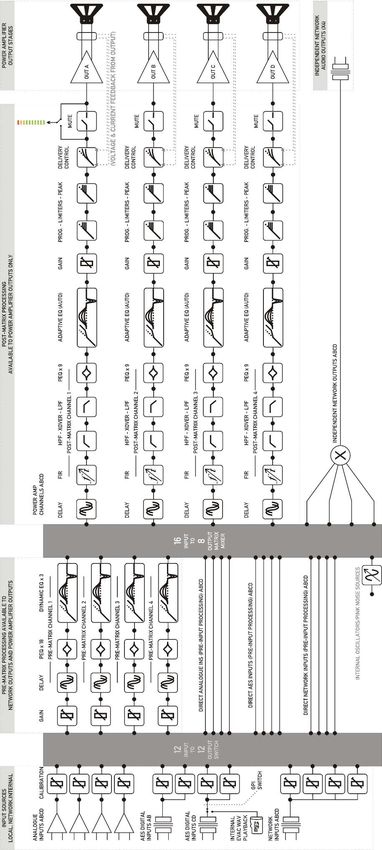
Page 2   APA Series Operator’s Manual

                         x ta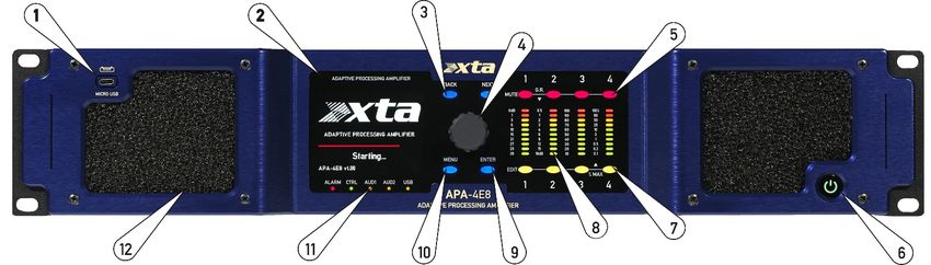
APA Series Operator’s Manual                                                                           Page 3

CONTENTS

INTRODUCING YOUR APA: ............................................................................................. 7

IMPORTANT SAFETY INSTRUCTIONS ........................................................................... 8

INSTRUCTIONS DE SECURITE IMPORTANTES ............................................................. 9

DECLARATION OF CONFORMITY .................................................................................. 10

INSTALLING YOUR APA: ................................................................................................11

        Unpacking                                                                                                   11

        Additional Symbols and Warnings                                                                             11

        Electrical Considerations                                                                                   12

        Mechanical Considerations                                                                                   13

CONNECTING TO YOUR APA: ........................................................................................ 14

        Audio Inputs Wiring                                                                                         14

        RS485 Output Wiring                                                                                         14

        Speaker Outputs Wiring                                                                                      15

GETTING TO KNOW YOUR APA: .................................................................................... 16

        Front Panel Layout and Controls                                                                             16

        Rear Panel Controls and Sockets                                                                             18

        Rear Panel Status LED Groups                                                                                19

        GPIO Connections                                                                                            19

        Signal Paths and Block Diagram                                                                              20

        Input Sources                                                                                               22

        AES Inputs                                                                                                  22

        Pre-Matrix Processing                                                                                       23

        Processed Input Channel Blocks                                                                              24

        Mix Matrix to Power Amp Processing Channels / Network Outputs                                               25

        Power Amp Channels Processing Blocks                                                                        26

         x ta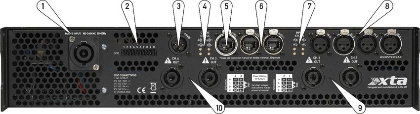
Page 4                                                                 APA Series Operator’s Manual

OPERATING YOUR APA: ............................................................................................... 28

        Powering Up                                                                                                28

        Powering Down and Returning Home                                                                           29

        Home Screen Layout                                                                                        30
             The “Monochrome Concept”                                                                             30

        User Metrics                                                                                              31
              Incoming Mains Monitor                                                                              31
              Amplifier Temperatures                                                                              32
              Quick Inputs Monitor                                                                                33
              Amp Channel Loads                                                                                   34
              Auto Scrolling of User Metrics                                                                      35

        Tri Colour Panel Metering                                                                                  36

        Output Channel Menu                                                                                       37
              Overview                                                                                            37
              Quick Gain Trim                                                                                     37
              Output Preset                                                                                       38
              Limiter Threshold                                                                                   38
              Output Polarity (Phase Reverse)                                                                     38

        System Menu                                                                                               39
              Overview                                                                                            39

UNDERSTANDING YOUR APA...................................................................................... 40

        Memories, Presets and File Structures                                                                     40
             Internal SD Card                                                                                     40
             USB Flash Drives: Firmware Upgrades and Presets/Memories                                             40
             The Concept of File Syncing                                                                          42
             Recalling Unit Memories                                                                              43
             Upgrading Firmware via Ethernet                                                                      45
             Upgrading Firmware via USB                                                                           51

        Mains RMS Current Limiter                                                                                  54

        Identify Unit                                                                                              55

        Default Audio                                                                                              55

        Default User Settings                                                                                      56

        Emergency Voice Evacuation Playback                                                                        57

        System Security                                                                                           58
              Overview and Locking Procedure                                                                      58
              Forgotten Your Password?                                                                            58
              System Warnings                                                                                     59

                                                                                              x ta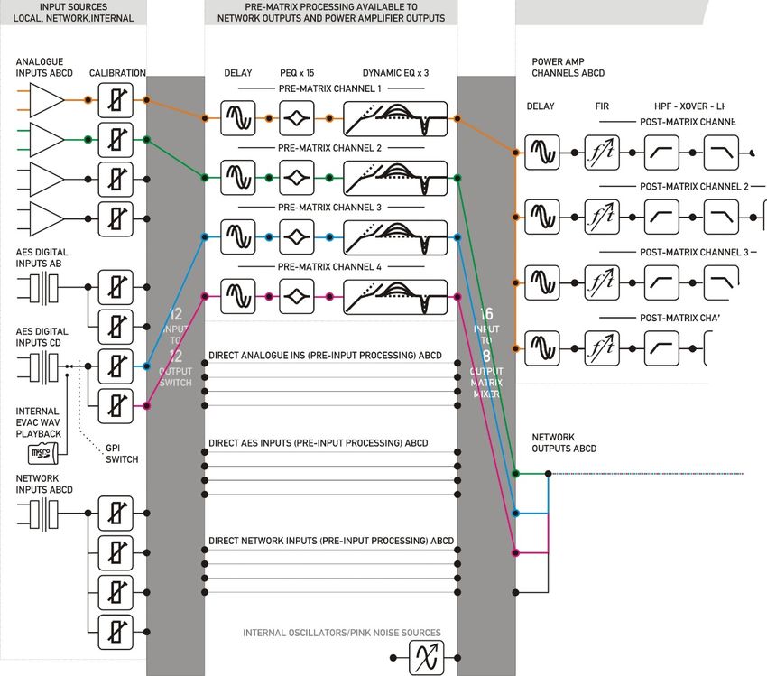
APA Series Operator’s Manual                                                                       Page 5

REMOTE CONNECTION TO YOUR APA ......................................................................... 61

       Overview                                                                                                61
             Connect to a Network                                                                              61
             Adhoc Connections (no DHCP Server)                                                                62
             Manual (fixed) IP Address Selection                                                               62
             AudioCore ID Number                                                                               63

LOOKING AFTER YOUR APA: ....................................................................................... 64

       Maintenance                                                                                             64

       Warranty                                                                                                64

PERFORMANCE OF YOUR APA: ................................................................................... 65

       Technical Specifications                                                                                65
             General                                                                                           65
             Audio System                                                                                      65
             Digital Audio                                                                                     66
             Storage & Losses                                                                                  66
             Physical and Mechanical                                                                           66
             Input Power                                                                                       67
             Output Power: Peak Performance                                                                    67
             Output Power: Continuous Performance                                                              68

       Power Measurement Test Types                                                                            69
             Test type 1: Continuous RMS Sine Wave                                                             69
             Test type 2: Continuous Pink Noise                                                                69
             Test type 3: Short Burst Sine Wave                                                                69
             Test type 4: Long Burst Sine Wave                                                                 69

        x ta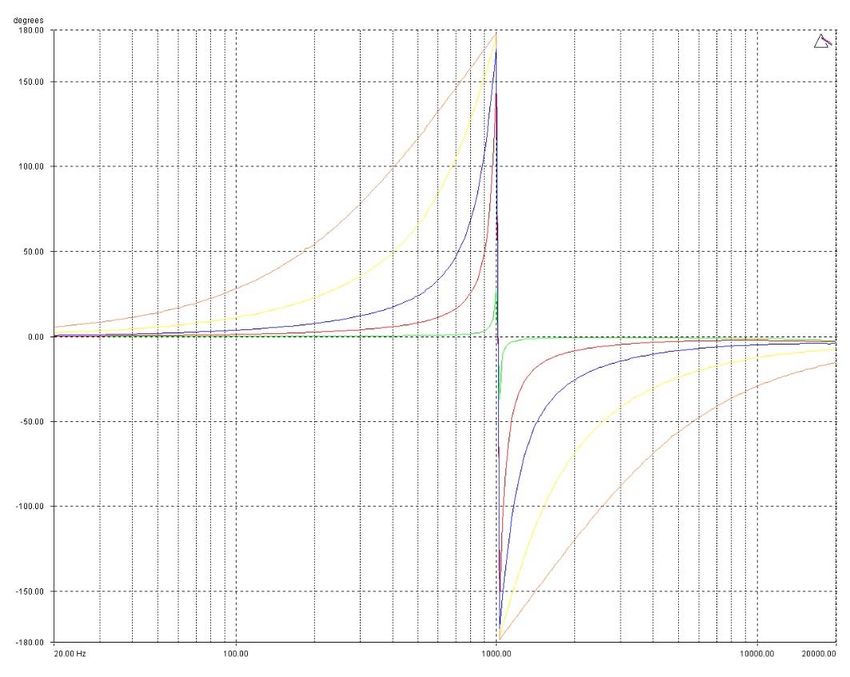
Page 6                                                    APA Series Operator’s Manual

ADDITIONAL INFORMATION ABOUT YOUR APA: ....................................................... 70

      Appendix I: Dynamic EQ                                                                  70
           Mode I: “Cut Above”                                                                70
           Mode II: “Cut Below”                                                               71
           Mode III: “Boost Above”                                                            72
           Mode IV: “Boost Below”                                                             73

      Appendix II: Program Limiter and Peak Limiter                                           74
           Program Limiter                                                                    74
           Peak Limiter                                                                       75
           Setting Accurate Limiter Thresholds — Program Limiter                              78
           Setting Accurate Limiter Thresholds — Peak Limiter                                 79
           Setting Appropriate Attack and Release Times                                       79

      Appendix III: Parametric Filter Types and Uses                                          80
           Standard Parametric EQ                                                             80
           High/Low Shelving EQ                                                               82
           Creating a Flat-topped EQ Response                                                 83
           Bandpass Filter                                                                    84
           Notch Filter                                                                       85
           All Pass Filter                                                                    86
           Phase Filter                                                                       87
           Low/High Pass Variable ‘Q’ Filter                                                  88

                                                                             x ta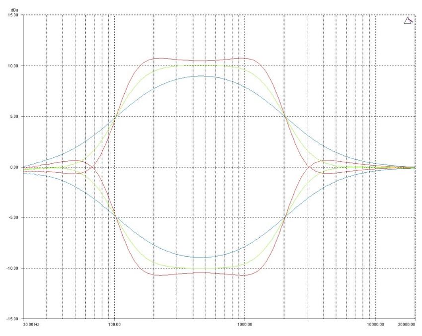
APA Series Operator’s Manual                                                       Page 7

Introducing Your APA:

Thank you for choosing an APA Series adaptive processing amplifier for your application.
Please spend a little time reading through this manual, so that you obtain the best possible
performance from the unit and become familiar with its operating requirements.

All XTA products are carefully designed and engineered for cutting-edge performance and
world-class reliability. If you would like further information about this or any other XTA
product, please contact us.

We wish you many years of flawless service from this unit and look forward to hearing from
you in the near future.

The APA Series — Adaptive Processing Amplification — are four channel Class D amplifiers
with extensive processing, connectivity and control capabilities. The new power and DSP
platforms have been designed to interact intelligently and adapt to prevailing conditions,
protecting drivers, and significantly enhancing performance from all speaker systems.

The power stages and processing tightly integrate with the power supply featuring 96k
analogue to digital converters not only on the analogue inputs but also directly at the speaker
outputs, monitoring voltage and current. Inputs and outputs are simultaneously being
processed by the DSP, along with data about the mains supply, allowing the APA to adapt and
correct to keep your music sounding better than ever.

The energy storage capabilities of the amplifier are such that it can also maintain peak power
output for periods that are musically useful and not just good on paper. The high efficiency of
the output stages and power supply also mean that heat production is reduced, resulting in
sustained long term power delivery, even in to very low impedance or difficult loads.

In addition to this adaptive processing, you still have full control over a powerful suite of
filtering and protection, including multiple bands of our legendary dynamic EQ, FIR filtering
and phase linearisation, ultra-transparent compression and limiting, plus all the classic
crossover and EQ components traditionally used to set up your system.

Add to this a fully flexible matrix with the ability to source audio either locally from AES or
analogue inputs, or via a networked audio connection (Dante/AVB). With Ether net based PC
remote software control also part of the package, you’ll understand why we don’t think this is
just an amplifier with some DSP built in…

       x ta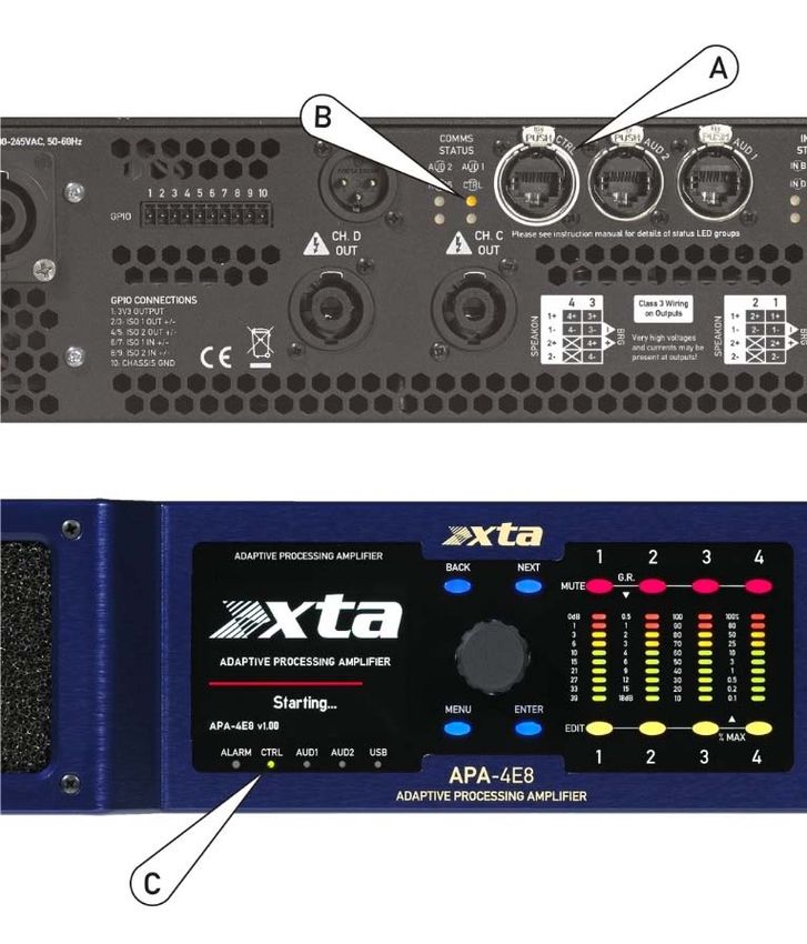
Page 8                                                                APA Series Operator’s Manual

Important Safety Instructions

                      CAUTION: RISK OF ELECTRIC SHOCK.
                                DO NOT OPEN

      The lightning flash with arrowhead                             The exclamation mark within an
      symbol within an equilateral triangle is                       equilateral triangle is intended to alert
      intended to alert the user to the presence                     the user of important operating and
      0f uninsulated “dangerous voltage”                             maintenance (servicing) instructions in
      within the product’s enclosure that may                        the literature accompanying the
      be of sufficient magnitude to constitute a                     appliance.
      risk of electric shock to persons.

WARNING: Apparatus with CLASS I construction shall be connected to a MAINS socket outlet with a protective
earthing connection.

WARNING: To prevent injury, this apparatus must be securely attached to the rack in accordance with the
installation instructions.er

 1.   Read these instructions.                              13. Unplug this apparatus during lightning storms or
 2.   Keep these instructions.                              when unused for a long period of time.
 3.   Heed all warnings.
 4.   Follow all instructions.                              14. Refer all servicing to qualified service personnel.
 5.   Do not use this apparatus near water.                 Servicing is required when the apparatus has been
 6.   Clean only with a dry cloth.                          damaged in any way, such as if the power-supply cord
                                                            or plug is damaged, liquid has been spilled or objects
 7. Do not block any ventilation openings, install in       have fallen into the apparatus, the apparatus has been
 accordance with the manufacturer’s instructions.           exposed to rain or moisture, does not operate
                                                            normally, or has been dropped.
 8. Do not install near any heat sources, such as
 radiators, heat registers, stoves or other apparatus       15. Do not expose this equipment to dripping or
 (including amplifiers) that produce heat.                  splashing and ensure that no objects filled with
                                                            liquids, such as vases, are placed on the equipment.
 9. Do not defeat the safety purpose of the polarized
 or grounding-type plug. A polarized plug has two           16. To completely disconnect this equipment from the
 blades with one wider than the other. A grounding-         AC mains, disconnect the power cord from the mains
 type plug has two blades and a third grounding             circuit breaker.
 prong. The wide blade or the third prong are
 provided for your safety. If the provided plug does not    17. This unit is fitted with a 3-wire power cord. For
 fit into your outlet, consult an electrician for           safety reasons, THE EARTH LEAD SHOULD NOT BE
 replacement of the obsolete outlet.                        DISCONNECTED IN ANY CIRCUMSTANCE.

 10. Protect the power cord from being walked on or
 pinched particularly at plugs, convenience
 receptacles and the point where they exit from the               18. Correct disposal of this product: This symbol
 apparatus.                                                 indicates that this product must not be disposed of
                                                            with household waste, according to the WEEE
 11. Only use attachments/accessories specified by          Directive (2012/19/EU) and your national law. This
 the manufacturer.                                          product should be taken to a collection center licensed
                                                            for the recycling of waste electrical and electronic
                                                            equipment (EEE). The mishandling of this type of
                                                            waste could have a possible negative impact on the
                                                            environment and human health due to potentially
           12. Use only with the cart, tripod, bracket or
                                                            hazardous substances that are generally associated
 table specified by the manufacturer, or sold with the
                                                            with EEE. At the same time, your cooperation in the
 apparatus. When a cart is used, use caution when
                                                            correct disposal of this product will contribute to the
 moving the cart/apparatus combination to avoid
                                                            efficient use of natural resources. For more
 injury from a tip over.
                                                            information about where you can take your waste
                                                            equipment for recycling, please contact your local city
                                                            office, or your household waste collection service.

                                                                                             x ta
APA Series Operator’s Manual                                                                             Page 9

     Instructions De Securite Importantes

                     ATTENTION: RISQUE DE CHOC ELECTRIQUE.
                                 NE PAS OUVRIR

          Le symbole représentant un éclair fléché                           Le point d’exclamation dans un triangle
          dans un triangle équilatéral a pour but                            équilatéral a pour but d’alerter
          d’alerter l’utilisateur de la présence                             l’untilisateur de la présence
          d’une “tension dangeruese” non isolée à                            d’instructions importantes concernant le
          l’intérieur du boitier, pouvant être d’une                         fonctionnement et la maintenance, dans
          force suffisante pour constituer un risqué                         la documentation qui accompagne
          d’électrocution.                                                   l’appariel.

     ATTENTION: Appareils de construction de CLASSE I doit être raccordé au réseau électrique via une prise de courant
     reliée à la terre.

     ATTENTION: Pour éviter toute blessure, cet appareil doit être solidement fixé à la torture, conformément aux
     instructions d'installation.

1.   Lisez ces consignes.                                         13. Débranchez l’appareil de la tension secteur en cas
2.   Conservez ces consignes.                                     d’orage ou si l’appareil reste inutilisé pendant une longue
3.   Respectez tous les avertissements.                           période de temps.
4.   Respectez toutes les consignes d’utilisation.
5.   N’utilisez jamais l’appareil à proximité d’un liquide.       14. Les travaux d’entretien de l’appareil doivent être eff
6.   Nettoyez l’appareil avec un chiff on sec.                    ectués uniquement par du personnel qualifié. Aucun
                                                                  entretien n’est nécessaire sauf si l’appareil est endommagé
7. Veillez à ne pas empêcher la bonne ventilation de              de quelque façon que ce soit (dommages sur le cordon
l’appareil via ses ouïes de ventilation. Respectez les            d’alimentation ou la prise par exemple), si un liquide ou un
consignes du fabricant concernant l’installation de               objet a pénétré à l’intérieur du châssis, si l’appareil a été
l’appareil.                                                       exposé à la pluie ou à l’humidité, s’il ne fonctionne pas
                                                                  correctement ou à la suite d’une chute.
8. Ne placez pas l’appareil à proximité d’une source de
chaleur telle qu’un chauff age, une cuisinière ou tout            15. N'exposez pas cet équipement au fait de tomber goutte à
appareil dégageant de la chaleur (y compris un ampli de           goutte ou au fait d'éclabousser et garantissez qu'aucun objet
puissance).                                                       rempli des liquides, comme les vases, n'est placé sur
                                                                  l'équipement.
9. Ne supprimez jamais la sécurité des prises bipolaires
ou des prises terre. Les prises bipolaires possèdent deux         16. Pour complètement débrancher cet équipement de la
contacts de largeur diff érente. Le plus large est le contact     conduite principale de courant alternatif, débranchez la
de sécurité. Les prises terre possèdent deux contacts plus        corde de pouvoir du disjoncteur de conduite principale.
une mise à la terre servant de sécurité. Si la prise du bloc
d’alimentation ou du cordon d’ali-mentation fourni ne             17. Cette unité est correspondue avec une corde de pouvoir
correspond pas à celles de votre installation électrique,         de 3 fils. Pour les raisons de sécurité, L'AVANCE DE TERRE
faites appel à un électricien pour eff ectuer le changement       NE DEVRAIT ÊTRE DÉBRANCHÉE DANS AUCUNE
de prise.                                                         CIRCONSTANCE.

10. Installez le cordon d’alimentation de telle façon que
personne ne puisse marcher dessus et qu’il soit protégé
d’arêtes coupantes. Assurez-vous que le cordon                          18. Mise au rebut appropriée de ce produit: Ce symbole
d’alimentation est suffisamment protégé, notamment au             indique qu’en accord avec la directive DEEE (2012/19/EU) et
niveau de sa prise électrique et de l’endroit où il est relié à   les lois en vigueur dans votre pays, ce produit ne doit pas
l’appareil; cela est également valable pour une éventuelle        être jeté avec les déchets ménagers. Ce produit doit être
rallonge électrique.                                              déposé dans un point de collecte agréé pour le recyclage des
                                                                  déchets d’équipements électriques et électroniques (EEE).
11. Utilisez exclusivement des accessoires et des appareils       Une mauvaise manipulation de ce type de déchets pourrait
supplémentaires recommandés par le fabricant.                     avoir un impact négatif sur l’environnement et la santé à
                                                                  cause des substances potentiellement dangereuses
                                                                  généralement associées à ces équipements. n même temps,
                                                                  votre coopération dans la mise au rebut de ce produit
                                                                  contribuera à l’utilisation efficace des ressources
          12. Utilisez exclusivement des chariots, des
                                                                  naturelles. Pour plus d’informations sur ’endroit où vous
diables, des présentoirs, des pieds et des surfaces de
                                                                  pouvez déposer vos déchets d’équipements pour le
travail recommandés par le fabricant ou livrés avec le
                                                                  recyclage, veuillez contacter votre mairie ou votre centre
produit. Déplacez précautionneusement tout chariot ou
                                                                  local de collecte des déchets.
diable chargé pour éviter d’éventuelles blessures en cas

              x ta
de chute.
Page 10                                                 APA Series Operator’s Manual

Declaration Of Conformity

We, the manufacturer:

XTA Electronics Limited,
The Design House
Vale Business Park
Worcester Road
Stourport on Severn
Worcestershire
England
DY13 9BZ

acknowledge our responsibility that the following products:

Kind of equipment:      Audio Amplifier
Commodity Code:         8518408990
Type Designation:       APA-4E8, APA-4E6

is manufactured:

in accordance with EMC Directive 2004/108/EC,
in compliance with the following norm(s) or document(s):
Technical Regulations: EN55103-1:1996, EN55103-2:1996

and

in accordance with the Low Voltage Directive 2006/95/EC,
in compliance with the following norm(s) or document(s):
Technical Regulations: EN/IEC60065:2002 7th Edition

Signed:         ……………………………………………………………………

Name:           Alex Cooper
Position:       Research and Development Manager
Date:           May 2017

                                                                        x ta
APA Series Operator’s Manual Page 11
Installing your APA:
Unpacking
After unpacking the unit, please check it carefully for any damage. If any is found,
immediately notify the carrier concerned - you, the consignee, must instigate any claim.
Please retain all packaging in case of future re-shipment.
The Design House
Vale Business Park
Worcester Road
Stourport on Severn
Worcs.
England
Tel +44 (0) 1299 879977
Fax +44(0) 1299 8799969
THIS WAY UP
Additional Symbols and Warnings
只有在高海拔地区使用不超过2000米。
Meaning of the symbol: Evaluation for apparatus only based on altitude not exceeding 2000m,
therefore it is the only operating condition applied for the equipment. There may be some
potential safety hazard if the equipment is used at altitude above 2000m.
只适合于非热带气候地区使用
Meaning of the symbol: Evaluation for the apparatus only based on temperate climate condition,
therefore it is the only operating condition applied for the equipment. There may be some
potential safety hazard if the equipment is used in tropical climate region,
x taPage 12 APA Series Operator’s Manual
Installing Your APA:
Electrical Considerations
The amplifier is fitted with a universal power supply which will operate world-wide — no user
setting is required.
Make sure power outlets conform to the power requirements listed on the back of the unit.
Damage caused by connecting to improper AC voltage is not covered by the warranty.
SAFETY WARNING
Where a MAINS plug or appliance coupler is used as the disconnect device, it should remain
readily operable.
Where the amplifier is mounted in a rack and permanently connected to the mains, then the
rack should be installed with a readily accessible connector or an ALL POLE circuit breaker
with 3mm breaking distances.
For PERMANENTLY CONNECTED APPARATUS provided neither with an all-pole MAINS
SWITCH nor an all-pole circuit breaker, the installation shall be carried out in accordance
with all applicable installation rules.
For safety reasons,
THE EARTH LEAD SHOULD NOT BE DISCONNECTED IN ANY CIRCUMSTANCE.
If ground loops are encountered consult the section on connecting your amplifier on page 14.
The wiring colours are:
230V AREAS: EARTH = GREEN AND YELLOW 120V AREAS: EARTH = GREEN
NEUTRAL = BLUE NEUTRAL = WHITE
LIVE = BROWN LIVE = BLACK
DO NOT USE THE UNIT IF THE ELECTRICAL POWER CORD IS FRAYED OR BROKEN. The
power supply cords should be routed so that they are not likely to be walked on or pinched by
items placed upon or against them, paying particular attention to cords and plugs and the
point where they exit from the appliance.
ALWAYS OPERATE THE UNIT WITH THE AC GROUND WIRE CONNECTED TO THE ELECTRICAL
SYSTEM GROUND. Precautions should be taken so that the means of grounding of a piece of
equipment is not defeated.
DO NOT REMOVE THE LID. Removing the lid will expose you to potentially dangerous
voltages. There are no user serviceable parts inside.
x taAPA Series Operator’s Manual Page 13
Installing Your APA:
Mechanical Considerations
To ensure that your APA performs to specification, it should be mounted in a suitable rack or
enclosure as described below. Like all high power amplifiers, it should be kept away from
other equipment which is sensitive to magnetic fields. Also, this amplifier may suffer a
substantial reduction in performance if it is subjected to, or mounted close to equipment
which radiates high RF fields.
Warning: To prevent injury, this apparatus must be securely attached to the rack in
accordance with the installation instructions.
When mounting the amplifier in a rack or enclosure:
Be aware that…
THE FRONT PANEL IS NOT CAPABLE OF SUPPORTING THE UNIT ON ITS OWN.
Make sure that the rear of the unit is adequately supported. The depth of the front panel
relative to the front of the rack may be adjusted by moving the side panel supports.
ENSURE THERE IS ADEQUATE VENTILATION.
The cooling fans suck cool air in through the front and blow hot air out at the rear of the unit
through the ventilating grills. The front and rear of the amplifier should have free exposure to
the air (i.e. in a rack leave the front & rear doors off), with 2cm air gap at the sides.
IF AIR IS NOT ALLOWED TO ESCAPE FROM THE REAR, OVER-HEATING WILL OCCUR.
Take care when mounting other equipment in the same rack.
Make sure that the rack unit has a separate earth connection (technical earth).
Please also see the notes regarding maintenance on page 64.
x taPage 14 APA Series Operator’s Manual
Connecting To Your APA:
Audio Inputs Wiring
Inputs - The inputs are made via 3-pin XLR connectors, which are electronically balanced and
should be connected via a high grade twin core screened cable, as follows:
MALE
PIN1: Screen (see NOTE)
XLR
PIN2: Hot (signal +)
PIN3: Cold (signal -)
The amplifier is designed to operate with fully balanced equipment and ground loops or loss
of performance may be experienced if connected to unbalanced sources. If it is unavoidable
however, the following wiring should be used. The cable should still be twin core plus screen.
PIN1: Screen - connected to the chassis of the unbalanced equipment - or left disconnected
at the unbalanced end.
PIN2: Hot (signal +)
PIN3: Cold (ground 0V)
NOTE: This amplifier is wired to the latest industry recommendations. PIN1 is connected
directly to the chassis/mains earth. If ground loops (mains hum) are encountered remove the
screen connection from the one end of the cable and leave it open circuit. If problems persist,
consult your dealer/supplier.
DO NOT TAMPER WITH OR ALTER ANY GROUND (EARTH) CONNECTIONS INSIDE THE
AMPLIFIER.
RS485 Output Wiring
The RS485 output is a data port for connection to other XTA equipment only. It is currently
not supported, however for reference, the following wiring should be used:
FEMALE
XLR
PIN1: Screen (see NOTE)
PIN2: Hot (signal +)
PIN3: Cold (signal -)
x taAPA Series Operator’s Manual Page 15
Speaker Outputs Wiring
The speaker outputs are via Neutrik Speakon connectors. 2 pole (NL2FC) or 4 pole (NL4FC)
connectors can be used.
NL2 & NL4
SPEAKON
Pin 1+: Hot
Pin 1-: Cold
Additionally Channel 1 Speakon connector carries Channel 2 output on Pins +2 & -2 to allow
easy bi-amping or bridged operation using a single NL4 connector.
Pin 2+: Hot Ch. 2
Pin 2-: Cold Ch. 2
In the same way, channel 3’s Speakon carries channel D on 2+ and 2-.
There must be no shared connections between channels.
The minimum load per single channel is 2 ohms. XTA recommend running channels with a
minimum 2.7 ohm load for maximum efficiency and long term power delivery (3 x 8 Ohm
loads in parallel).
As the currents involved are very high, and to ensure best performance, the speaker cables
should be kept as short as possible and conform to the following minimum requirements:
APA-4E8: 22 Amps into 4 Ohm speaker loads.
APA-4E6: 13 Amps into 4 Ohm speaker loads.
When operating the amplifier into loads of less than 4 Ohms, be aware that the current
capacity of the speaker cables will need to be increased above the values quoted above.
Do not connect the inputs/outputs to any other voltage source such as a battery, mains source
or power supply, regardless of whether the amplifier is turned on or off.
Do not run the output of any amplifier channel back into another channel’s input and do not
parallel or series-connect an amplifier output with any other amplifier output.
Connecting To Your Amplifier: Bridged (Mono) Operation
Use Channel 1 or 3 Output Speakon connector and connect as follows:
Pin 2+: Hot
Pin 1-: Cold
When operating in bridged mode, the minimum impedances are doubled.
The minimum load in bridged mode is 4 ohms.
x taPage 16 APA Series Operator’s Manual
Getting To Know Your APA:
Front Panel Layout and Controls
1: USB ‘OTG’ Socket: APA works in Host mode, so USB memory sticks can be plugged in here
to update firmware, download presets, save log files, and upload EVAC playout messages.
Please see notes on page 40 for more information.
2: LCD Screen: This full colour display primarily operates in black and white, only showing
warnings in red — at a glance if you see no colour then you can be sure your APA is operating
normally!
3: Back and Next Navigation Keys: From the Home Screen, these will cycle through various
“User Metrics” detailing the amplifier’s performance and current status — please see page 30
for more information on the “User Metrics”. They are also used to navigate the main menu
system and output menus.
4: Velocity Sensitive Encoder: Used to alter parameter values, and may also be used to cycle
through “User Metrics” from the Home Screen.
5: Mute Keys: These will mute the output channel processing sections of the amplifier. They
do not affect input processing or audio sent back out on the network. Please refer to the
system block diagram on page 22 for more information.
6: Standby/Home Key: If illuminated RED then the amplifier is in standby (no display shown
but DSP is still active and amplifier is still available on the network). Press and hold for 3
seconds to power up. A three second press will also put the amplifier into standby. Use as a
quick “Exit” from any menu to get back to the Home Screen and User Metrics.
7: Output Edit Keys: These directly access output channel gains, as well as other output
related information such as limiter thresholds, polarity switching, and current preset
information.
8: Tri-colour metering: As all meter elements can display green, yellow or red, APA can
show many different things on the meters. Default meter mode shows output channel dB
from limit. More information on page 36.
9: Enter Key: Used to confirm selections and enter sub-menus where appropriate.
10: Menu Key: Press to access system wide parameters and specific sub-menus.
x taAPA Series Operator’s Manual Page 17
Front Panel Layout and Controls cntd…
11: Status and Warning Indicators: Permanent indication of the following:
ALARM: Illuminates to show any condition APA needs to warn you about —
the list of possible warnings is covered on page 59.
CTRL: Illuminates when a connection is made from the CTRL (control)
Ethernet socket on the rear panel, to a valid network.
AUD1: Illuminates when a connection is made from the AUD1 (audio)
Ethernet socket on the rear panel, to a valid network.
AUD2: Illuminates when a connection is made from the AUD2 (audio)
Ethernet socket on the rear panel, to a valid network.
USB: Illuminates when a USB stick is connected and data is being
transferred. Do not disconnect USB device if LED is flashing.
12: Air Vents: The amplifier draws air in from the front and exhausts from the back. Please
ensure there is adequate ventilation space front and back — see page 64 for more information
on looking after your amplifier.
x taPage 18 APA Series Operator’s Manual
Rear Panel Controls and Sockets
1: Mains Input Socket: Mains connection is via a 32A ”Powercon” type plug. Supply voltage is
100-240V AC. This unit must be earthed.
2: GPIO Socket: Connections are via Phoenix “mini” connectors. They can be used to provide
feedback of fault conditions, as well as being used to trigger different amplifier events such
as mutes, standby, and emergency evacuation message playback. Please see page 19 for
more information on the current capabilities.
3: RS485 Output Socket: This socket is intended for diagnostics only. It is not intended to be
used as a method of primary remote control of this amplifier. Please see page 14 for more
information.
4: Comms Status LEDs: This group of 4 tricolour LEDs shows if the current Ethernet and
RS485 comms ports are connected and in use. More information on their various modes of
operation is given on page 19.
5: CTRL Ethernet Socket: This RJ45 socket connects the amplifier to a valid Ethernet
network for remote control and monitoring.
6: AUD1 & AUD2 Ethernet Sockets: This pair of RJ45 sockets connect the amplifier to a valid
Ethernet network for transmission of audio data.
7: Input Status LEDs: This group of 4 tricolour LEDs can show various information about
signal level or lock status in AES mode. Please see page 19 for more information.
8: Analogue and AES Digital Input Sockets: By default these four sockets are four analogue
inputs, but individual pairs of sockets can be switched (via remote software and memory
recall via the front panel) to receive AES digital audio. AES input on channel A’s XLR provides
a stereo stream designated AES A + AES B; AES input on channel C’s XLR provides a stereo
stream designated AES C + AES D. When an AES input is selected, the “other” channel of the
pair is disabled (you cannot input analogue into channel B XLR if A&B are set to AES mode).
9: Speaker Output Sockets 1&2: The primary speaker outputs are via Neutrik Speakon
connectors on 1+ and 1-. Two pole (NL2FC) or four pole (NL4FC) connectors can be used.
Additionally Channel 1 Speakon connector carries Channel 2 output on Pins +2 & -2 to allow
easy bi-amping or bridged operation using a single NL4 connector.
10: Speaker Output Sockets 3&4: The primary speaker outputs are via Neutrik Speakon
connectors on 1+ and 1-. Two pole (NL2FC) or four pole (NL4FC) connectors can be used.
Additionally Channel 3 Speakon connector carries Channel 4 output on Pins +2 & -2 to allow
easy bi-amping or bridged operation using a single NL4 connector.
x taAPA Series Operator’s Manual Page 19
Rear Panel Status LED Groups
There are two sets of status LEDs on the rear panel — one set beside the input XLR sockets
and one set beside the network sockets. Both sets are tri-colour LEDS and so can show a
variety of information using colour and steady/flashing indication as explained below.
The input status LEDs show both analogue signal preset and approaching clipping point, and
AES lock status and sample rate.
In analogue input mode, the corresponding input channel’s LED will be off in the absence of
signal and will show signal present in green and 1dB below clip in red.
Input level too high — above +18dBu and approaching clipping point of input!
Analogue signal present above -60dBu — all OK
No analogue signal present, or below -60dBu
In AES input, indicators for inputs A and C will show digital input status and sample rate. The
choice of AES or analogue may be selected remotely on a pair-by-pair basis, so A&B can still
be showing analogue level , with C showing digital status for the C&D AES stream, and vice
versa.
Flashing red — AES input active, no signal lock (so no audio!)
Steady red — locked to 48k AES stream
Steady yellow — locked to 96k AES stream (ideal)
Steady green — locked to 192k AES stream
GPIO Connections
The amplifier is equipped with a 10 way mini-Phoenix type connector that offers a pair of logic
level inputs for triggering different aspects of APA’s operation, and a pair of logic level
outputs for simple remote reporting on various statuses.
It is wired as follows:
1: 3V3 OUTPUT
2/3: ISO 1 OUT +/-
4/5: ISO 2 OUT +/-
6/7: ISO 1 IN +/-
8/9: ISO 2 IN +/-
10: CHASSIS GND
Currently emergency wav file playback from the SD card is offered, but this feature set will be
enriched in later firmware releases. Please see the section about the SD card file structure
and wav file format on page 40.
x taPage 20 APA Series Operator’s Manual
Signal Paths and Block Diagram
x taAPA Series Operator’s Manual Page 21
x taPage 22 APA Series Operator’s Manual
Input Sources
APA is exceptionally flexible as regards input routing and mixing, and can receive audio from
a variety of sources: analogue audio, stereo AES audio, multichannel networked audio, along
with internal noise and sine wave generators and audio file playback from the internal SD
card (for emergency evacuation messages only).
With the exception of the internal oscillators, all the other audio sources are available on the
input side of the 12 x 12 switched routing matrix.
The four DSP “Input” processing channels, can receive signals from any of the available
signal sources but please note the following:
- As AES inputs share physical XLR connection with two analogue inputs, you cannot
source analogue input A and AES A at the same time. This is also true for analogue
source C and AES C.
- AES C+D shares an input to the switching matrix with mono “wav” file playback for
emergency evacuation messaging. This is enabled by either a contact closure on the
local amplifier, or by a network message. Please see the section on page 54 for more
information.
AES Inputs
APA can accept a pair of AES3 digital audio streams in stereo channel pairs. As explained in
the section above, these share the physical connectors for analogue inputs A and C for the
two digital inputs. They can be selected on a channel pair basis so one pair of digital and one
pair of analogue inputs can be in use together if required.
The AES inputs accept sample rates from 32kHz up to 192kHz, at 24 bit resolution. In AES
input mode, rear panel indicators for inputs A and C will show digital input status and sample
rate.
Flashing red — AES input active, no signal lock (so no audio!)
Steady red — locked to 48k AES stream
Steady yellow — locked to 96k AES stream (ideal)
Steady green — locked to 192k AES stream
Via the Quick Inputs Monitor on the front panel, the AES input levels can be verified by
selecting Quick Inputs Monitor using BACK and NEXT from the home screen and then turning
the encoder to select AES Inputs:
x taAPA Series Operator’s Manual Page 23
Pre-Matrix Processing
APA’s processing is conveniently split between input signal conditioning before it reaches the
full mix matrix, and output/loudspeaker specific processing dedicated to each of the four
power amplifier channels.
With this in mind, the pre-matrix processing has been designed to offer as much flexibility as
possible, as it may be used for network audio processing that does not involve the local power
amplifier at all. For example — the amplifier may be configured to run a 4-way system, as one
half of a stereo set-up. This would mean that three of the four available input processing
paths would remain unused. This need not be the case of course, as they can be utilised to
process incoming audio from another source, and output this on the network.
The diagram below illustrates this example.
In this example, analogue input A is feeding all four post-matrix processing channels (to the
local power amplifiers) with analogue input B being processed but not connected to any
further local processing, instead being fed back out onto the network for use elsewhere.
Similarly, AES input stream C&D is picked up and processed before being sent back out onto
the network.
x taPage 24 APA Series Operator’s Manual
Processed Input Channel Blocks
Each processed input channel contains the following blocks:
Gain: the input level to the processing channel (pre-matrix) may be trimmed to adjust the
level up-stream of any output processing or network outputs.
Delay: over 1000mS available on each input channel in 0.01mS steps.
Remember that this delay will affect all outputs that it feeds — those might be local power
amplifier channels and/or network outputs.
PEQ EQ: 18 bands of parametric equalisation are available on each input channel. Each band
is switchable to a wide variety of filter topologies including:
Standard parametric EQ;
Low Shelving;
High Shelving;
Low Pass (including adjustable ‘Q’/slope);
High Pass (including adjustable ‘Q’/slope);
All Pass (including adjustable ‘Q’/phase shift);
Phase (90 degree shift with adjustable frequency);
Notch;
Bandpass.
The operation and use of these different types is covered in Appendix III starting on page 80.
Dynamic EQ: 3 bands of DEQ are available on each input channel.
Each band can be set to operate in four modes:
Boost above threshold (upward expansion);
Cut above threshold (standard downward compression);
Boost below threshold (upward compression);
Cut below threshold (standard downward expansion).
Additionally, the filter’s type can be switched between operating as a standard parametric EQ,
to a high or low shelving filter, or run full range, whereupon the filtering behaviour is
disabled, and the DEQ band operates as a compressor/expander as determined by the mode.
The operation and use of the dynamic EQ is covered in Appendix I starting on page 70.
x taAPA Series Operator’s Manual Page 25
Mix Matrix to Power Amp Processing Channels / Network Outputs
Following the input switching and before the power amplifier
processing and network outputs, the mix matrix allows full
mixing of up to 16 sources to each of the 8 outputs.
The 16 sources are derived from:
- Processed input channels x 4;
- Direct analogue inputs x 4;
- Direct AES digital inputs x 4;
- Network audio inputs x 4.
The 8 outputs are to the four further processing channels
connected directly to the power amplifiers, and four network
audio outputs that can then be used externally to the
amplifier by other devices (not just APA).
Note that this is a full mix matrix — different to the input
switcher — signals from any source can be mixed if required.
The remote software presents this as two independent sets
of “sends” — one page for the local power amps and one for
the network outputs. This is because there are two modes of
set-up:
- A “crosspoint” matrix with Boolean on/off choices in
a grid, with associated automatic adjustment of gains to
maintain 0dB at the output (so for example sending two
channels to an output will drop their respective send gains
by 3dB so they sum to 0dB).
- An advanced mix matrix with all sources having fully
adjustable gains.
x taPage 26 APA Series Operator’s Manual
Power Amp Channels Processing Blocks
Each power amplifier channel contains the following blocks:
Delay: over 1000mS available on each input channel in finer sub-sample 300nS steps.
This delay normally is used for driver time alignment and so works at very high resolution: a
300nS step size equates to a distance adjustment of 0.1mm.
FIR Filtering Block: FIR filtering coefficient data may be loaded into this section (when
designing a preset for the output channel) which can be used to equalise the signal path
instead of using the IIR filters (that is, the crossover filters and PEQ sections). It can also be
used in addition to these filters to linearise the phase response for the channel. Used in this
way, it gives the flexibility of real time adjustment of all EQ, as well as guaranteeing linear
phase, and with lower latency than standard “linear phase” filters.
Crossover Filters: Slopes from 6dB/Octave up to 48dB/Octave may be chosen with standard
filter topologies Bessel, Butterworth, and Linkwitz Riley. The high and low pass filters are
independent so allowing for asymmetrical crossovers to be realised.
PEQ EQ: 9 bands of parametric equalisation are available on each input channel. Each band
is switchable to a wide variety of filter topologies including:
Standard parametric EQ;
Low Shelving;
High Shelving;
Low Pass (including adjustable ‘Q’/slope);
High Pass (including adjustable ‘Q’/slope);
All Pass (including adjustable ‘Q’/phase shift);
Phase (variable 180 degree shift with adjustable frequency);
Notch;
Bandpass.
Note that 48dB slope crossover filters will bypass two bands of PEQ each.
The operation and use of these different types is covered in Appendix III, starting on page 80.
Adaptive EQ: These two bands of dynamic EQ are hidden from the user and are automatically
set up and adjusted by the amplifier during “adaptive” operation. This functionality will be
increasingly enabled in a future release.
Gain: Individual output channels’ gain trim allows driver level differences to be incorporated
into preset data and can be further adjusted by the user (if permitted). The front panel gain
trim also works at this point (but is separate from this).
Program (RMS) Limiter: The program limiter is designed to control the continuous level and
limit the long term level to a driver to prevent overheating of a driver voice coil. The look-
ahead design of the program limiter means that it can accurately detect signals that will
exceed its threshold and apply gain reduction to them whilst still applying the desired attack
time. Attack and release time constants may be automatically set, if desired, according to the
x ta
high pass crossover frequency for a particular channel.APA Series Operator’s Manual Page 27
Peak Limiter: The peak limiter is the last processing block in the signal path and will catch
any peaks that the program limiter lets through, due to its (desirable) variable attack time.
With this use in mind, the threshold adjustment for the peak limiter is set in “dB above” the
program limiter and it will track the threshold of the program limiter as it is adjusted, always
sitting at the required number of dB above it. It is designed to limit over excursion of drivers,
in particular LF drivers, and prevent mechanical damage caused by this.
For more information on how the limiters work, please see Appendix II, starting on page 74.
Delivery Control: This is a sophisticated feedback system that measures the real time voltage
and current being delivered to the actual output load. Using the same quality 24 bit 96k
analogue to digital converters as employed at the analogue inputs, the voltage and current
(and so the power and impedance) may be calculated and used to model the heating effects
on a driver. The long term power delivery may then be adapted to prevent overheating or
premature failure of the speaker. This system’s parameters are defined by the speaker
manufacturer in the preset (along with the usual crossover points, EQ etc.) and may not be
visible to the end user.
Channel Mute: front panel mute controls operate at this point in the signal path, just before
the power amplifiers.
x taPage 28 APA Series Operator’s Manual
Operating Your APA:
Powering Up
Your APA will power up in standby the first time it is connected to the mains supply. The
Power/Home button will be illuminated red. A brief press on the Power/Home button will
wake up the display and meters for 5 seconds allowing you to check levels, IP address, and
operate mutes if you need to adjust these before you switch on.
To power up, hold the Power/Home button for 3 seconds — the display will wake up and you
will see the countdown on screen:
The Power /Home button will change to green and the amplifier will start its power up
sequence:
1) Delaying for a random period (less than 2 seconds) to prevent multiple amplifiers all
powering up together under remote control causing excessive current draw
2) Checking and enabling the power supply
3) Checking and enabling each output channel and relay
4) Finally, unmuting the DSP and fading up the audio
Once this sequence is complete, the amplifier will show its home screen:
x taAPA Series Operator’s Manual Page 29
Hint: During start-up, the mute button LEDs will flash if they are going to unmute
automatically at the end of the sequence. They are active during the entire start-up sequence
and can be muted/unmuted at any time if not set as required.
Powering Down and Returning Home
Powering down also requires a 3 second hold on the Power/Home button.
A brief press of the Power/Home button whilst the amplifier is active will return to the home
screen, and also display the hint about how to power down:
Hold Power/Home for 3 seconds to see the countdown, at which point the amplifier will go
into standby and the output relays will disengage, and the main power supply (PSU) will
power down. The display will briefly show:
Before the screen and all indicators and meters are extinguished. The Power/Home button
will change to red.
Hint: If you wish to leave the screen and metering active in standby, hold the MENU button
and briefly press Power/Home when the amplifier is in standby. Another press of
Power/Home will clear this. This mode is useful for checking presets or setting mains
current limits before powering the amplifier up fully.
It is also a requirement that USB access for syncing presets and uploading of new firmware is
only possible in standby to avoid potentially dangerous mistakes!
x taPage 30 APA Series Operator’s Manual
Home Screen Layout
The home screen shows you important useful information about your APA.
The name of your APA as it appears on the network control software is shown first. If you’ve
not chosen a name APA will give it a random one so it can be easily identified if you have
multiple amplifiers on the network.
The next section shows the name of the current user memory or, “None” if one is not being
used.
The next section down is the status bar which will display any important information about the
“health” of your APA, as well as hints about operation and the current security level — see
page 58 for how this works.
At the bottom of the screen the amplifier’s IP address and Unit ID are shown. The IP address
will be assigned to the amp by your network’s DHCP server — if you want a direct 1:1
connection to a laptop and cannot connect to a server, then the amplifier can generate its own
local IP address. Please see the section about connecting to a network, starting on page 61.
The “Monochrome Concept”
To make your APA as intuitive and simple as possible to operate, we have designed the user
interface to be useful from a distance as well as up close. This design concept extends from
the information shown on the LCD to the metering and its various modes. Considering the
LCD in this case, you may not be aware that the LCD is a full colour QVGA display. We choose
to show all information in black and white as it offers the best contrast and readability.
To highlight any conditions that will result in a loss of audio or reduction in performance, we
solely use red on the display. In this way it is easy to confirm, from any distance, if there are
any things that require user intervention or attention. If the amplifier is operating normally
and all channels are able to output audio, you will never see any colour on the display.
Similarly with the metering — red LEDs are only used when there is an automatic reduction of
level in a channel, or a fault condition.
To summarise - no red = no worries!
x taAPA Series Operator’s Manual Page 31
User Metrics
Incoming Mains Monitor
Your APA uses high resolution converters to measure the incoming mains voltage and
instantaneous current draw so that it can adjust output power levels if you have set a current
limit, and also to ensure that the mains voltage remains within the safe operating range of the
unit.
Peak current is shown as a held dot within the current meter. If the mains voltage drops too
low for satisfactory operation, or goes too high for safe operation, the voltage portion of the
screen will change to red, and the ALARM LED on the front panel will illuminate. Depending
on how low the mains voltage drops, the amplifier may go into full protection and disable the
outputs until the condition has cleared or been remedied.
If the current draw of the amplifier begins to exceed the user set limit (see page on page 54
for how to do this) the current meter will additionally display how much gain reduction is
being automatically applied to stay operational and keep playing.
Note that protection information will only be displayed if below the speaker protection limiter
thresholds.
x taPage 32 APA Series Operator’s Manual
Amplifier Temperatures
Your APA has over 20 temperature sensors, monitoring several points on each individual
channel’s circuitry, as well as various points within the power supply, and the output filters.
This data is all used to ensure that the amplifier can adapt its behaviour to stay operational
and keep playing as long as possible.
An algorithm uses this data to create an overall “temperature” of the amplifier and this is
displayed along with the power supply temperature.
Should the amplifier’s temperature rise to a dangerous level, the relevant portion of the
screen will change to red and the ALARM LED on the front panel will illuminate.
Individual channels’ temperatures can cause the amplifier to apply protection on a channel by
channel basis to prevent overall shut down protection and keep playing as long as possible.
The display will show applied gain reduction if this is operating below the speaker protection
limiter thresholds.
As this operation may affect the frequency balance of your system (for example bass drivers
being reduced in level relative to mid-high drivers), you can minimise this happening by
ensuring adequate cooling and adhere to minimum load specifications as detailed on page 15
of this manual.
x taAPA Series Operator’s Manual Page 33
Quick Inputs Monitor
The LED meters on your amplifier always show levels relating to the power amplifier outputs,
be this absolute output level, level relative to the limiter, or compressor gain reduction1.
However, you can also check the incoming levels using this metric display.
All four inputs of the selected type are displayed at the same time, with real time bar
metering and numerical readout. Select the input type by turning the encoder when on this
screen, and choose between analogue inputs as above, or AES inputs, or network inputs.
Note that this is NOT the method for choosing inputs and switching between them — this is
only possible through the remote software or by selecting a unit preset with different input
selections. As the AES and Analogue connections are shared, some monitoring scenarios
may not always be possible — for example, you cannot monitor AES inputs C&D if Analogue
has been switched in. Under these circumstances the screen will show:
x ta
1
In future firmware releases, compressor gain reduction and power output will be available as metering optionsPage 34 APA Series Operator’s Manual
Amp Channel Loads
In addition to the more obvious 24 bit 96k analogue to digital converters (ADCs) fitted to the
inputs of your amplifier for analogue signal conversion, your APA has has eight additional
ADCs of the same quality fitted directly at the output terminals. These are used to monitor
the speaker output voltages and currents in real time and are fed directly back into the DSP,
so near-instantaneous monitoring of power and distortion can be realised. This hardware
addition is crucial to the adaptive nature of your APA.
It also permits real time monitoring of the load impedances using this metric display.
The first time this user metric display is shown after power up, it will display “---“ in place of
a measured impedance, until voltage and current data at a sufficient level has been collected.
This may take a few seconds, and the measurement algorithm is weighted to respond to
instantaneous drops in impedance so that over current protection can operate quickly to
prevent damage to output circuitry.
If the level on any channel drops below the threshold for accurate readings to be taken, the
pervious value will be held and shown in parenthesis as below, where channels 2 and 4 reads
are now not live.
x taAPA Series Operator’s Manual Page 35
Auto Scrolling of User Metrics
As explained on each user metrics screen, holding either the BACK or NEXT key for 2 seconds
will toggle between auto mode and manual mode. Auto scrolling mode will switch to the next
metrics screen every 5 seconds, and will include the home screen in this loop. Auto scrolling
enabled is shown by the small “auto” in the top right corner of the metric title area on the
display.
In manual mode, BACK and NEXT do not scroll through the home screen. To return to the
home screen, press the Power/Home button briefly.
x taPage 36 APA Series Operator’s Manual
Tri Colour Panel Metering
The LED metering on the front panel of your APA is made up of tri colour LED elements,
capable of displaying red green or yellow. This allows the meters to dynamically alter their
colour and offer much better visual feedback.
They can be switched to operate in a number of different
modes2 but the default is to show the power amplifier
output levels, pre-mute. The meters are linked to the
limiter so that they show a dB level relative to the limiter
threshold for each channel, and their ballistics (attack
and release times) will reflect those chosen for that
channel’s limiter.
Adjusting the limiter threshold for a channel will
therefore change the metering shown for that channel,
and so for a fixed input level, lowering the limiter
threshold will show more level on the meter.
They also show gain reduction once a channel’s level has exceeded the limiter threshold, by
changing colour and “wrapping round”, beginning to read downward from the top in red. So,
the above snapshot shows channels 1 & 3 just on the threshold of limiting with channel 2
having a further 10dB until limit and channel 4 still 27dB from limit.
If the signal increases further, the meter will not simply
“stop” at 0dB, but will change to red and begin to light
red LEDS from the top down.
Channel 1 has just exceeded the limiter threshold by
approximately 0.5dB at this point, and in the third
snapshot it’s clear that channel 1 and 3 are hard into
limit with 4 and 9dB of limiting (gain reduction)
respectively. The “G.R.” scale shown on the panel
between channels 1 & 2 should be used for this purpose.
Note that this meter reads PRE-MUTE and so will always
show signal even if the channel mute is enabled.
x ta
2
In future firmware releases, compressor gain reduction and power output will be available as metering optionsAPA Series Operator’s Manual Page 37
Output Channel Menu
Overview
Pressing one of the output edit buttons allows adjustment and viewing of parameters
associated with the power amplifier output channels, including quick gain trim, checking of
the limiter threshold and adjustment of the output polarity. The list of output menu options
deliberately starts with the quick gain trim, so that it’s easy to adjust this with just a single
button press. Navigation through the list is with the BACK and NEXT keys.
Press the EDIT button again to exit, or press the Power/Home key.
Quick Gain Trim
Adjust the channel’s output level by +12dB. This is a trim only, and is relative to the output
gain set within the channel’s preset. It is reset to 0dB when a new preset is recalled.
Pressing the channel’s Mute will change the readout to red, as the main LED output meters
may be reading pre-mute and so still register level.
x taYou can also read