Optical vortex lattice: an exploitation of orbital angular momentum - De Gruyter
←
→
Page content transcription
If your browser does not render page correctly, please read the page content below
Nanophotonics 2021; aop

Research article

Liuhao Zhu, Miaomiao Tang, Hehe Li, Yuping Tai and Xinzhong Li*

Optical vortex lattice: an exploitation of orbital
angular momentum
https://doi.org/10.1515/nanoph-2021-0139                                     1 Introduction
Received March 31, 2021; accepted May 25, 2021;
published online June 9, 2021
                                                                             In 1974, Ney and Berry discovered the dislocations in wave
                                                                             trains that inspired the interest in phase singularities and
Abstract: Generally, an optical vortex lattice (OVL) is
                                                                             optical vortices [1]. In 1992, Allen et al. [2] discovered that
generated via the superposition of two specific vortex
                                                                             photons possess orbital angular momentum (OAM), which
beams. Thus far, OVL has been successfully employed to
                                                                             afforded them an additional degree of freedom. An optical
trap atoms via the dark cores. The topological charge (TC)
                                                                             vortex (OV) possesses a helical phase, exp(jmθ), and OAM,
on each optical vortex (OV) in the lattice is only ±1.
                                                                             mħ, where m is the topological charge (TC) and θ is the
Consequently, the orbital angular momentum (OAM) on
                                                                             azimuthal coordinate. OV exhibits many applications,
the lattice is ignored. To expand the potential applications,
                                                                             including optical imaging [3], production of optical twee-
it is necessary to rediscover and exploit OAM. Here we
                                                                             zers [4–7], and optical communication [8, 9]. To satisfy the
propose a novel high-order OVL (HO-OVL) that combines
                                                                             requirements of versatile applications, an OV lattice (OVL)
the phase multiplication and the arbitrary mode-
                                                                             containing multiple unit OVs was extensively studied
controllable techniques. TC on each OV in the lattice is
                                                                             [10–19]. Generally, OVL is generated via the superposition
up to 51, which generates sufficient OAM to manipulate
                                                                             of OV beams with the OV inlay in the intensity pattern.
microparticles. Thereafter, the entire lattice can be modu-
                                                                                  As a typical OVL, in 2007, the optical Ferris light field
lated to desirable arbitrary modes. Finally, yeast cells are
                                                                             was generated via the superposition of two Laguerre–
trapped and rotated by the proposed HO-OVL. To the best
                                                                             Gaussian (LG) beams with specific pairs of TCs [20]. It could
of our knowledge, this is the first realization of the complex
                                                                             suitably trap cold and quantum degenerate atomic sam-
motion of microparticles via OVL. Thus, this work suc-
                                                                             ples. In 2009, this beam was successfully applied to trap
cessfully exploits OAM on OVL, thereby revealing potential
                                                                             single rubidium (87Rb) atoms [21]. In the same year, an ac-
applications in particle manipulation and optical tweezers.
                                                                             driven atomic quantum motor was proposed based on this
Keywords: micro-particle manipulation; optical vortex;                       beam [22]. To freely modulate OVL modes, a circular OVL
orbital angular momentum; physical optics.                                   was produced via the superposition of two concentric
                                                                             perfect optical vortices [23]. Furthermore, OVL was
                                                                             manipulated into versatile structures [24–26]. However, the
                                                                             dark core of OVL is barely exploited in atomic manipula-
                                                                             tion. It appears that the physical quantity of OAM on OVs in
                                                                             OVLs is being ignored. Why is this? The answer is con-
*Corresponding author: Xinzhong Li, School of Physics and                    cealed in the quantity of OAM. TC on a unit OV is always ±1,
Engineering, Henan University of Science and Technology, Luoyang,            producing a negligible OAM of ±ħ per photon. Conse-
471023, China; and State Key Laboratory of Transient Optics and              quently, OAM, producing the “wrench force,” in OVL has
Photonics, Xi’an Institute of Optics and Precision Mechanics of CAS,
                                                                             not been exploited. Conversely, the trapping and rotation
Xi’an, 710119, China, E-mail: xzli@haust.edu.cn. https://orcid.org/
0000-0002-6426-4043                                                          of tiny objects are essential in some advanced applications,
Liuhao Zhu, School of Physics and Engineering, Henan University of           e.g., in light-driven motors [27, 28], detection of DNA
Science and Technology, Luoyang, 471023, China; and State Key                rotation [29], hydromechanics [30], and cell sorting [31, 32].
Laboratory of Transient Optics and Photonics, Xi’an Institute of Optics           Thus, OAM should be utilized, and OVL with high-
and Precision Mechanics of CAS, Xi’an, 710119, China
                                                                             order TC (HO-TC) should be developed. To address this
Miaomiao Tang and Hehe Li, School of Physics and Engineering,
Henan University of Science and Technology, Luoyang, 471023, China
                                                                             challenge, in 2013, Chen et al. reported a kind of OVL with
Yuping Tai, School of Chemical Engineering and Pharmaceutics,                HO-OAM, which was generated via specific LG modes [33].
Henan University of Science and Technology, Luoyang, 471023, China           However, the number of OVs was related to their orders,
  Open Access. © 2021 Liuhao Zhu et al., published by De Gruyter.         This work is licensed under the Creative Commons Attribution 4.0 International
License.
2        L. Zhu et al.: Optical vortex lattice

thus causing the unmodulation of the OVL mode. Further,          and 3, respectively. To facilitate the analysis, the phase
in 2018, they modified the method to obtain arbitrary             ring was unrolled laterally into a rectangle and discretized
HO-OVL by employing several weighted factors [34].               to a sequence under the limiting conditions. The phase
Notably, a power index was applied to the complex                shown in Figure 1(a1) was discretized to an arithmetic
amplitude of the LG beam in their methods, limiting the          sequence that started from aq and possessed q terms
modulation of the mode for specific applications. These           [Figure 1(a2)], where a1 = 0 and aq = 2π. Similarly, the phase
works motivated us to separate the complex amplitude of          shown in Figure 1(b1) was discretized into three arithmetic
light into the amplitude and phase terms, which were             sequences that started from b1 and possessed p terms
modulated afterward.                                             [Figure 1(b2)], where b1 = 0 and bp = 2π. Note that the size of
     Therefore, the major aim of this work is to develop a       each term was equal between Figure 1(a2) and (b2). In this
mode-controllable HO-OVL. In this paper, we first                case, p = q/3, i.e., the two OV beams were superposed
explained why TC of each OV in OVL is identically equal to       completely, the interference petals appeared in absence of
±1. Thereafter, following the definition of TC, the phase of      unit OVs [21, 23]. Then, let us consider that the two OV
the superposed optical field was separated and multiplied         beams were partially superposed. Firstly, the phase shown
to obtain HO-TC. Moreover, by combining the arbitrary            in Figure 1(a1) was the superposed outer ring. In this case,
curve technique, the OVL structure was freely shaped, and        the number of discretized terms of inner ring was only one
the arbitrary HO-OVL was simultaneously obtained.                less than that of the outer ring, i.e., p = (q − 1)/3, and the
Further, HO-TC of each OV was verified, and the energy            results are illustrated in Figure 1(c). There were only four
flow and OAM around OV were analyzed. Finally, the                pairs of terms of 0 and 2π in the superposed area. Simul-
physical quantity of OAM was exploited in OVL, after             taneously, there was merely one period increasing from
which experiments employing HO-OVL were performed to             0 to 2π around each singularity anticlockwise. According to
exhibit its application.                                         the definition of TC in Eq. (1), the TC of unit OVs in OVL is
                                                                 always −1. Thereafter, the phase shown in Figure 1(b1) was
                                                                 exchanged to be the superposed outer ring. Similarly, in
2 Principles and methods                                         this case, p = (q + 1)/3, and four positive unit OVs (TC = +1)
                                                                 were produced around where the phase that was clockwise
To generate mode-controllable HO-OVL, two OV beams               increased from 0 to 2π [Figure 1(d)]. Generally, considering
were shaped into desired arbitrary structures. Next, OVL         the different superposed OV beams, the only changes are in
was constructed via the superposition of these deform-           the numbers and signs of the unit OVs in OVL. Further-
able OV beams. The complex amplitude of OVL was                  more, the magnitude of TC of each OV remained un-
divided into the amplitude and phase terms. The phase            changed, as obtained from previous references [21].
term was extracted and modulated to obtain HO-TCs.               Consequently, an additional operation should be per-
Subsequently, the modulated phase multiplied the                 formed on the superposed phase to obtain HO-OVs from
amplitude term to reconstruct a new complex amplitude            OVL.
of OVL, i.e., HO-OVL.                                                 To multiply TC of the unit OV in OVL, a multiplication
    In addition, the generation of HO-TC of the unit OVs in      factor, l, is applied to the superposed phase distribution as
OVL is crucial. Thus, the reason why OVs are always ±1 in        follows:
OVL must be clarified. Let us begin from the definition of TC                                 1
through the following [35]:                                                         lm =      ∫ ∇ (lψ(s))ds                  (2)
                                                                                           2π C
                              1
                        m=      ∫∇ψ(s)ds                   (1)   and combined with Eq. (1), the phase, ψ(s), of OVL can be
                             2π C
                                                                 substituted by ψ0(s) as follows:
where ψ(s) denotes the OVL phase, C is a closed path                                     ψ0 (s) = lψ(s)                      (3)
around the singularity, i.e., the unit OV, and ∇ is the vector
differential operator. Explicitly, the magnitude of TC de-           Thus, the phase term of OVL can be reconstructed as
pends only on the phase around the singularity.                  exp[jψ0(s)]. Notably, the exponential function, e, is a pe-
     The number of singularities on the circle can be            riodic function, which truncates the phase into several
deduced, as clarified in our previous work [23]. Here we         periods, 0 − 2π. Consequently, HO-TC of OV would be ob-
attempt to answer the question, “why TC of unit OVs in OVL       tained in OVL. Figure 1 shows the schematic of the prin-
is always ±1?” For instances, Figure 1(a1) and (b1) shows        ciple. Therein, TC of OV in OVL was multiplied by l = 3. The
the phase distributions of the two OV beams with TCs = −1        upper row is a 3D representation of the multiplication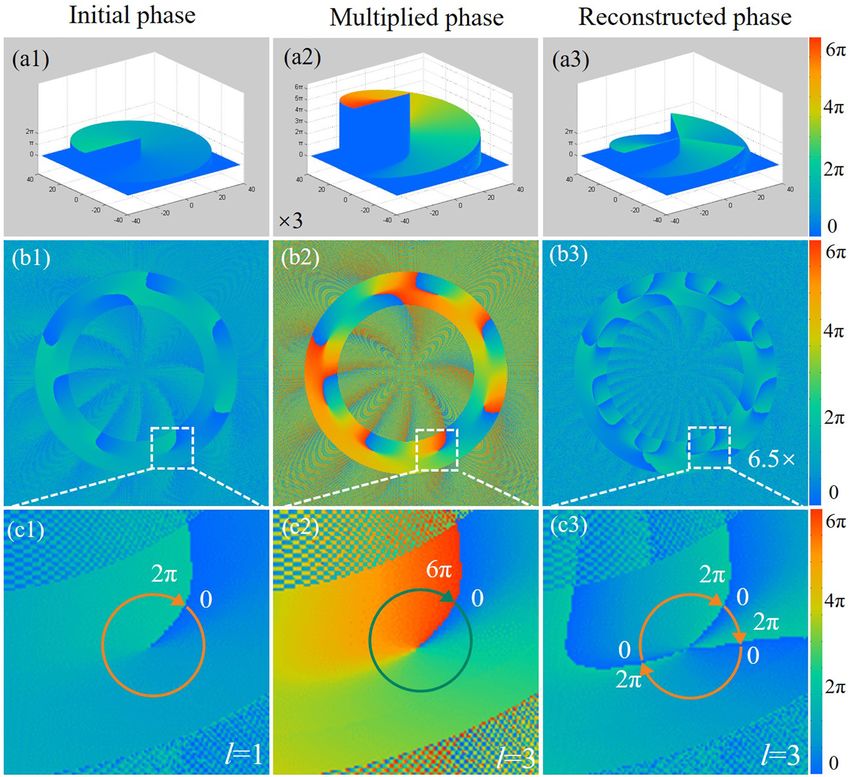
L. Zhu et al.: Optical vortex lattice      3

                                                                                                   Figure 1: Schematic illustration of why TC of
                                                                                                   the unit OVs in OVL is always ±1.
                                                                                                   (a1) And (b1) OV beams with TCs of −1 and 3,
                                                                                                   respectively. (a2) And (b2) horizontal
                                                                                                   expansion and discrete arithmetic
                                                                                                   sequences. (c) And (d) superposition in two
                                                                                                   different cases, and the white and black
                                                                                                   circle arrows represent the negative and
                                                                                                   positive unit OVs, respectively.

process of one unit OV. The middle and lower rows repre-                                     G(η, ξ ) = G1 (η, ξ ) + G2 (η, ξ )              (6)
sent the phase reconstruction of OVL and the magnification
                                                                                 Equation (6) can be rewritten as a general formula for
of the specific OV, respectively.
                                                                             the complex amplitude of the light field:
     HO-OVL exhibits the modulation of the OV in a circular
structure. However, to function as OAM during multiple                                          G(η, ξ ) = A(η, ξ )ejψ(η,ξ )                 (7)
microparticle manipulations, the HO-OVL mode should be
                                                                                Applying l to the phase term of OVL, the complex
arbitrarily modulated. To achieve this, the structures of the
                                                                             amplitude, HO-OVL, can be reconstructed:
OV beams were shaped to desired modes by the holo-
graphic beam-shaping technique before the superposition                                        G0 (η, ξ ) = A(η, ξ )ejψ0 (η,ξ )              (8)
[24]. The computer-generated hologram of the shaped OV is
written as follows:                                                               In this case, the circular curve was selected as the
                                                                             major research object. Here, x0(t) = Ri cost, y0(t) = Ri sint,
                    n              1      T             ⃒⃒       ⃒⃒          n = 100, R1 = 1.6 mm, R2 = 1.9 mm, m1 = 4, m2 = −4, and N =
       H i (x, y) = ∑ Ai    T ⃒⃒      ⃒⃒ ∫ φi (x, y, t)⃒⃒c′2 (t)⃒⃒dt   (4)
                                                                             |m1 − m2|, where Ri is the parameter that controls the radius
                   i=1        ⃒        ⃒
                           ∫0 ⃒c′2 (t)⃒dt 0
                                                                             of the beam, n is the circular thickness, m1 and m2 are TCs of
where Hi(x, y) represents a vortex beam along the arbi-                      the two superposed OV beams, and N is the number of OVs
trary curves; Ai is a Gaussian function that regulates the                   on the ring. Figure 2(b1) shows the phase term of OVL.
amplitude distribution of the curve; n is a parameter that                   Assuming l = 3, the reshaped phase, ψ0, and the final
controls the width of the curve, the term |c′2(t)| =                         truncated phase are shown in Figure 2(b2) and (b3),
[x′0(t)2 + y′0(t)2]1/2 with t ∈ [0, T = 2π]; and φi(x, y, t) is the          respectively.
phase term. The shaped OV beam is generated at the
frequency plane:
                   ∞
   Gi (η, ξ ) = ∫ ∫−∞ H i (x, y)exp[ − 2jπ(ηx + ξ y)]dxdy              (5)   3 Generation and validation
    OVL is generated via the superposition of two shaped                     To generate and verify the effectiveness of the proposed
vortex beams and is written as follows:                                      method, the experiment was set, as shown in Figure 3. The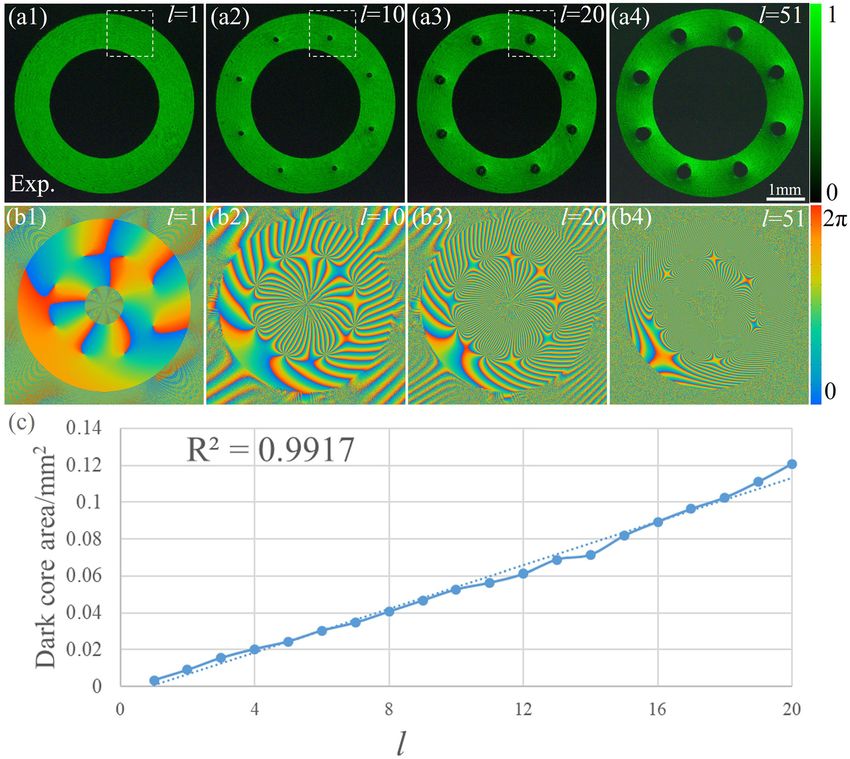
4 L. Zhu et al.: Optical vortex lattice
Figure 2: HO-TC generation via phase multiplication.
(a1)–(a3) Initial, multiplied, and HO phases of OV, respectively. (b1)–(b3) Phase reconstruction of OVL. (c1)–(c3) Magnification patterns of the
specific OV phase.
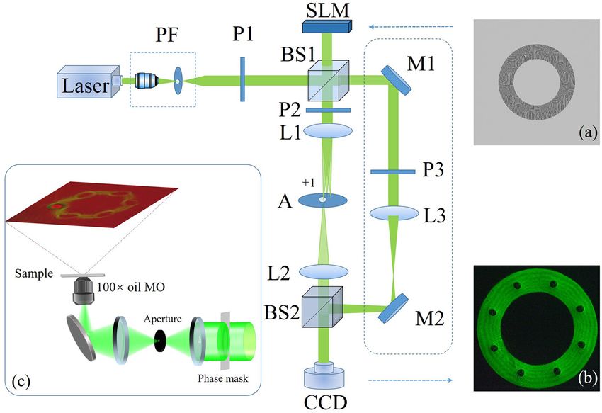
Figure 3: Schematic of the experimental
setup. PF, pinhole filter; P1–P3, polarizers;
BS1 and BS2, beam splitters; SLM, spatial
light modulator; L1–L3, convex lenses; A,
aperture; M1 and M2, mirrors; CCD, charge-
coupled device.
(a) Amplitude-modulated phase mask,
(b) intensity of HO-OVL recorded by CCD,
and (c) module of the particle manipulation.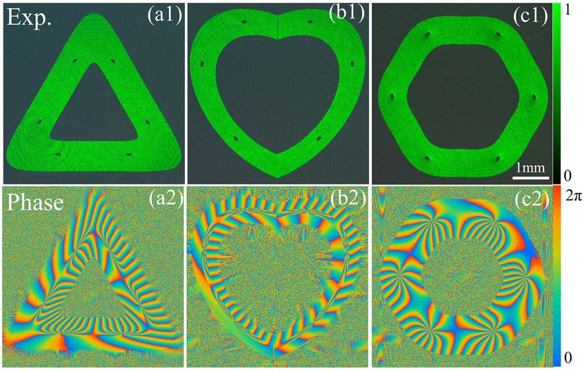
L. Zhu et al.: Optical vortex lattice         5

                                                                                        Figure 4: Interferograms of HO-OVL and a
                                                                                        spherical beam.
                                                                                        (a1)–(a3) Experimental intensity patterns of
                                                                                        l = 1, 2, and 3, respectively, and (b1)–(b3)
                                                                                        their corresponding interferograms.

532-nm laser beam irradiated the spatial light modulator         4 Results and discussion
(SLM, HOLOEYE, PLUTO-VIS-016; pixel size, 8 × 8 μm2;
resolution, 1920 × 1080 pixels) after expanding and colli-       To assign a significant role to OAM in HO-OVL, it was
mating. The beam was modulated by SLM and reflected               employed as a key parameter of l of each photon possessing
onto a 4F system that is composed of two lenses (L1 and L2),     OAM of lħ. The capacity of OAM of OV in the lattice was
with the same focal length (15 cm). Finally, it was recorded     determined by the maximum of l. In this work, the multi-
by a charge-coupled device (CCD, Basler acA1600-60gc;            plication times were up to 51 (i.e., l = 51), which is the
pixel size, 4.5 × 4.5 μm2) on the second Fourier plane. The      maximum to the best of our knowledge. Moreover, the
optical path that is encircled by the dotted lines is a refer-   structure of the dark core gradually changed into a drop
ence light path to execute interference.                         shape beyond that value (l = 51). However, HO-OVLs with
     A binary mask (1024 × 1024 pixels) was designed to          increased OAM can be obtained for special applications if
eliminate the stray light, as shown in Figure 3(a). It is        the phase mask and experimental elements are designed
expressed as T = bw[A(r, θ)] × exp{i[lφ(r, θ) + 2πx/d]}, where   and arranged carefully, respectively.
bw(·) is a binary function and d is the period of the blazed          To exploit OAM in HO-OVL, the distributions of OAM
grating. Since OVL was produced on the SLM plane, the 4F         and the energy flow must be demonstrated and analyzed.
system was employed to output and record HO-OVL at the           The parameters of HO-OVL were changed to thicken the
desired position.                                                intensity ring for sufficient photons, where n = 150 and l = 1,
     To verify the existence of OVs and determine their          10, and 20, respectively. In experiments, OAM was diffi-
corresponding TCs in HO-OVL, a spherical beam was                cultly determined in the solution. Consequently, OAM and
employed as reference light to execute interference.             the energy flow were numerically calculated by the previ-
Figure 4 illustrates the intensity patterns and interfero-       ously reported methods [2, 36–38]. The equation of the
grams. The sizes of the dark cores increased with                energy flow is written as follows:
increasing l. A spiral fork fringe pattern appeared in the
                                                                                        ϵ0
interferogram patterns at the corresponding position of                    P(η, ξ ) =      Im[G∗0 (η, ξ ) ⋅ (∇)G0 (η, ξ )]        (9)
                                                                                        4ω
each dark core. The results verified that OVs existed in
HO-OVLs. Furthermore, TC of OV was determined by the             where ε0 is the vacuum permittivity, ω = k·c is the circular
fork number minus one, which is consistent with the              frequency of light, c is the velocity of light in a vacuum, and
default values of l. Consequently, HO-OVL was success-           k is the wavenumber. OAM is typically deduced by the
fully generated in this case (Figure 5).                         following equation [38]: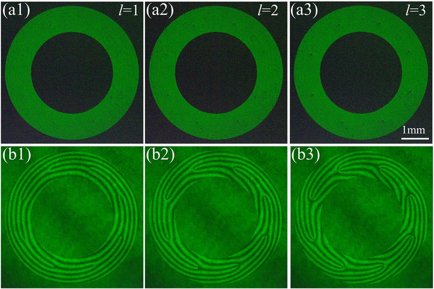
6           L. Zhu et al.: Optical vortex lattice

Figure 5: (a1)–(a4) HO-OVL intensity patterns with different ls (1, 10, 20, and 51, respectively). (b1)–(b4) Corresponding phase patterns of the
top row. (c) Area of the dark core versus l.

                         ϵ0                                                       the energy flow. Therein, the white arrows represent
            J(η, ξ ) =      r × Im[G∗0 (η, ξ ) ⋅ (∇)G0 (η, ξ )]
                         2ω                                                (10)   the direction and magnitude of the flow. To observe the
                     = η ⋅ Pξ + ξ ⋅ Pη                                            details, specific OVs were magnified, as displayed in
                                                                                  Figure 6(b1)–(b3). It can be observed that the ring current of
where r is the position from the origin. Since the calcula-
                                                                                  the energy flow was formed around each OV. Moreover, the
tion center is the optical axis, the results cannot reflect the
                                                                                  ring current increased dramatically with increasing l. This
properties of OV on the ring. Therefore, the above equation
                                                                                  trend also appeared in the density patterns of OAM
requires a displacement to change the calculation center.
                                                                                  [Figure 6(c1)–(c3)], which was calculated utilizing the
Hence:
                                                                                  center of the specific OV as the rotating axis of OAM.
    J 0 (η − η0 , ξ − ξ 0 ) = (η − η0 ) ⋅ P ξ −ξ 0 + (ξ − ξ 0 ) ⋅ P η−η0   (11)        To quantificationally analyze the change in the energy
                                                                                  flow, OAM, and rotation speed with increasing l, the data at
where η0 and ξ0 are the coordinate parameters that control                        four sampling points marked in the second row were
the calculation center.                                                           calculated and plotted [Figure 6(d1), (d2) and (d3)]. Among
     Employing the aforementioned theory, the simulations                         them, the rotation speed was numerically simulated via the
of the energy flow and OAM of HO-OVL were numerically                             method in Ref. [39] under our experimental conditions. The
performed with different ls. For comparison, the size of the                      results indicated that the energy flow, OAM, and rotation
dark core was designed to be constant with increasing l.                          speed increased monotonically with increasing l. Further-
Figure 6(a1)–(a3) shows the intensity patterns containing                         more, the magnified times of the energy flow, OAM, and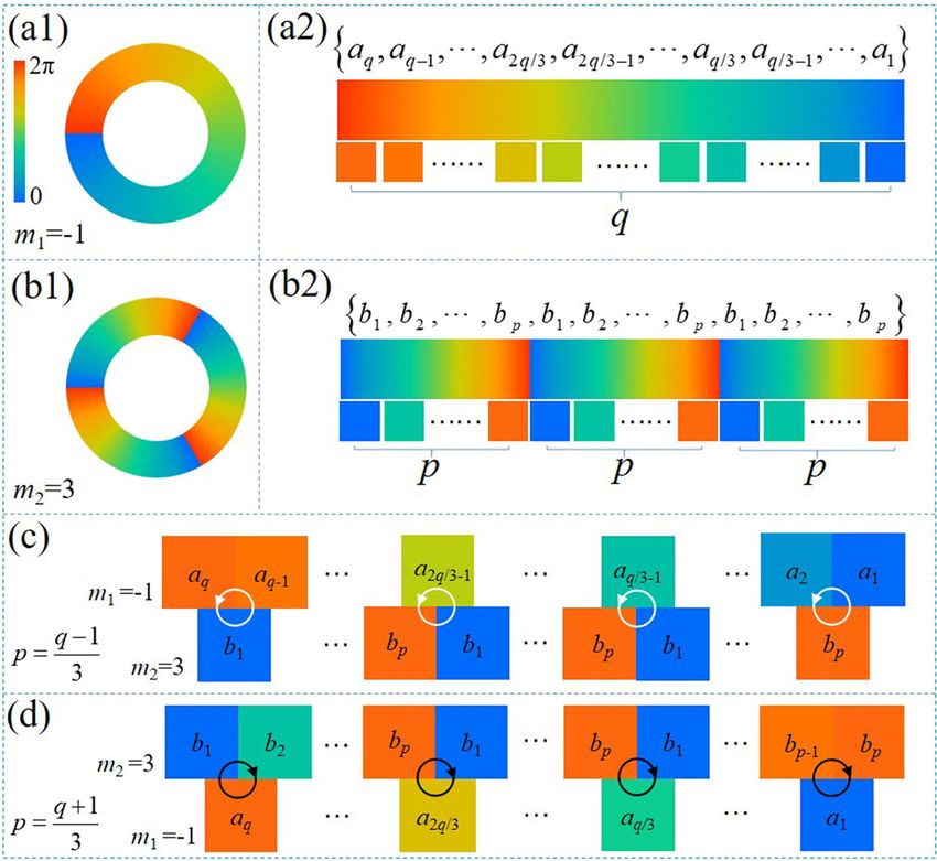
L. Zhu et al.: Optical vortex lattice           7

Figure 6: Change in the energy flow and OAM with increasing l.
(a1)–(a3) Energy flows, (b1)–(b3) local magnification of OVs in the lattice, and (c1)–(c3) OAM density distributions. The axis of symmetry is
located at the center of the specific OV, i.e., at point O. (d1), (d2), and (d3) Energy flows, OAM, and rotation speed at specific points versus l,
respectively. Note that energy flow and OAM are normalized, respectively.

rotation speed are approximately equal to the value of l. For                  To exploit OAM in OVL, i.e., assign it an essential role,
instance, the times of the energy flow and OAM were both                    microparticle manipulation experiments were conducted.
equal to 9.7 and 17.8 for l = 10 and 20 compared to l = 1,                 Yeast cells were selected as the samples to highlight the
respectively. For a specific sampling point, the slopes of the              applications in biosciences. Oil immersion microscope
fitting lines were different, whereas the times were approx-                objective (1.2 NA, 100×) was employed to focus HO-OVL
imately equivalent because of the different initial values.                [Figure 3(c)] onto the samples.
The results hinted that the unit OVs in HO-OVL could be                        We executed three groups of experiments to verify the
employed to rotate and spin microparticles of different sizes.             capacity of OAM. Firstly, the yeast cell with a size of 5–8 μm
8          L. Zhu et al.: Optical vortex lattice

was irradiated by HO-OVL with l = 1 for 20 s. The cell was                 the spinning of the yeast resumed, as shown in
trapped in OV with slight Brownian motion. Subsequently,                   Figure 7(b1)–(b5) (refer to Visualization 2 for details).
the beam was switched into HO-OVL with l = 6, and the cell                 Compared with the single OV beam, one of the advantages
began to spin under the influence of OAM. This process is                   of OVL is the fact that it contains multiple OVs. Conse-
shown in Figure 7(a1)–(a5) (details are contained in Visuali-              quently, HO-OVL can simultaneously manipulate multiple
zation 1). In the experiments, the yeast cell stopped rotating             particles. This ability was demonstrated and verified by
after spinning at a certain angle (∼90°). During the spinning of           simultaneously rotating two yeast cells, as shown in
the cells, they always attained equilibrium, where OAM did                 Figure 7(c1)–(c5) (refer to Visualization 3 for details). More
not supply sufficient wrench force to continue the spin. This               complex motions of the cell, as desired, could be obtained
phenomenon is dominated by the shape match between the                     with more complex combinations of l.
dark core and yeast cell. If the dark core occupying OV was a                   Thus far, OAM has demonstrated tremendous ability in
perfect circle, the cell would spin ceaselessly. The orientation           HO-OVL. To satisfy the special requirements of multiparticle
location of the particles could be determined by shaping the               manipulation, the versatile modes of HO-OVL should be
structure of the dark core. Consequently, OAM of OV in the                 freely controlled. Owing to the arbitrary curve technique, we
lattice would play a dominating role in rotating the cells. To             generated HO-OVLs with specific modes, e.g., the triangular,
the best of our knowledge, this is the first implementation of              heart-like, and hexagonal modes, as shown in Figure 8. TC of
particle rotation by OVL.                                                  each OV in the lattice was multiplied into 10. Despite
     Moreover, OAM could achieve complex motion                            employing the same mode, the curve function was not
comprising spin and revolution around OV (the second row                   unique. Owing to the difference in the curve function,
demonstrates these properties). The yeast cell was alter-                  different curve parameters were adjusted based on the
natively irradiated by HO-OVL with l = 10. Here, the radius                experiment. Figure 8 shows the intensities and corresponding
of OV was greater than that of the yeast, thus facilitating its            phase distributions of the three modes. For the triangular
capture by the ring around OV, followed by its rotation                    HO-OVL, the equations and parameters were set as
upon the application of OAM. Next, l was changed to 6, and                 x0(t) = Ri(−2cost + 0.54cos2t), y0(t) = Ri(−2cost − 0.54cos2t),

Figure 7: Manipulation of yeast cells by HO-OVL.
(a1)–(a5) Irradiation of the yeast cell by HO-OVL with l = 1, which was subsequently switched to l = 6. (b1)–(b5) Irradiation of the yeast cell by
HO-OVL with l = 10, which was switched into l = 6. (c1)–(c5) Simultaneous rotations of two yeast cells.
L. Zhu et al.: Optical vortex lattice 9
Figure 8: HO-OVL with versatile modes.
(a1)–(c1) Intensity patterns of triangular,
heart-like, and hexagonal HO-OVLs.
(a2)–(c2) Corresponding phase distribu-
tions of (a1)–(c1). l = 10 in all the instances.
n = 100, R1 = 0.8 mm, R2 = 1.1 mm, m1 = 3, and m2 = −3. For the techniques. To guarantee beam quality, the OAM order of
heart-like HO-OVL, the equations and parameters were set each OV in the lattice was increased up to 51, exceeding the
as x0(t) = |Ri(3cost − 2cos2t)|, y0(t) = −Ri(2cost − 3cost), limit of the traditional OVL. Thus, OAM of each OV in HO-OVL
n = 100, R1 = 0.8 mm, R2 = 0.9 mm, m1 = 3, and m2 = −3. For was exploited and unleashed. The manipulation of the yeast
the hexagonal HO-OVL, the equations and parameters were cell indicated that HO-OVL could induce the complex motion
set as x0(t) = Ricost(1 − 0.035cos6t), y0(t) = Ricost of particles under the influence of OAM. Our results can pave
(1 − 0.035cos6t), n = 100, R1 = 1.6 mm, R2 = 1.9 mm, m1 = 3, the way for future trapping and manipulation of multiple
and m2 = −3. Employing an arbitrary curve function, the microparticles, particularly in biosciences [29–32].
corresponding HO-OVL could be explicitly produced, as
desired. Author contributions: All the authors have accepted
Comparing with the holographic optical tweezers responsibility for the entire content of this submitted
[40, 41], the proposed optical tweezers based on HO-OVL manuscript and approved submission.
can trap multiple particles, and simultaneously execute Research funding: National Natural Science Foundation of
complex motion, especially the spin and orbital rotations. China (Nos. 11974102, 11704098, 11974101), State Key
The dark cores and OAM of the proposed HO-OVL were Laboratory of Transient Optics and Photonics (No.
pivotal, and this would facilitate new potential applica- SKLST201901), and Key Scientific Research Projects of
tions that can be limited only by our imagination. From Institutions of Higher Learning of Henan Province
the experiments, the yeast cells did not rotate a complete Education Department (No. 21zx002).
period due to the asymmetry of the dark cores. We believe Conflict of interest statement: The authors declare no
that the rotation with a complete period, even the orbital competing financial interest.
rotation on the whole OVL, can be realized by accurately
modifying the size, structure, and intensity distribution of
the unit OVs. The issue will be studied in the near future. References
Further, the force field distribution and more complex
motions of multiple particles, especially the nano- [1] J. F. Nye and M. V. Berry, “Dislocations in wave trains,” Proc. R.
particles, are the other areas that should be extensively Soc. Lond., vol. A336, pp. p165–p190, 1974.
studied soon. [2] L. Allen, M. W. Beijersbergen, R. Spreeuw, and J. Woerdman, “Orbital
angular momentum of light and the transformation of Laguerre–
Gaussian laser modes,” Phys. Rev. A, vol. 45, p. 8185, 1992.
[3] X. Qiu, F. Li, W. Zhang, Z. Zhu, and L. Chen, “Spiral phase contrast
5 Conclusions imaging in nonlinear optics: seeing phase objects using invisible
illumination,” Optica, vol. 5, p. 208, 2018.
[4] X. Z. Li, H. X. Ma, H. Zhang, et al., “Is it possible to enlarge the
Summarily, we proposed HO-OVL with controllable modes trapping range of optical tweezers via a single beam?” Appl. Phys.
employing the phase multiplication and arbitrary curving Lett., vol. 114, p. 081903, 2019.10 L. Zhu et al.: Optical vortex lattice
[5] X. Z. Li, H. Zhang, H. X. Ma, et al., “Grafted optical vortex with [24] L. Li, C. Chang, X. Yuan, et al., “Generation of optical vortex array
controllable orbital angular momentum distribution,” Opt. along arbitrary curvilinear arrangement,” Opt. Express, vol. 26,
Express, vol. 27, p. 22930, 2019. p. 9798, 2018.
[6] T. Chantakit, C. Schlickriede, B. Sain et al., “All-dielectric silicon [25] B. Chen, J. Geng, F. Zhou, L. Song, H. Shen, and N. Xu, “Quantum
metalens for two-dimensional particle manipulation in optical state tomography of a single electron spin in diamond with
tweezers,” Photonics Res., vol. 8, p. 1435, 2020. Wigner function reconstruction,” Appl. Phys. Lett., vol. 114,
[7] J. A. Rodrigo, M. Angulo, and T. Alieva, “All-optical motion control p. 041102, 2019.
of metal nanoparticles powered by propulsion forces tailored in [26] X. Li and H. Zhang, “Anomalous ring-connected optical vortex
3D trajectories,” Photonics Res., vol. 9, no. 1, 2021, https://doi. array,” Opt. Express, vol. 28, p. 13775, 2020.
org/10.1364/prj.408680. [27] Y. Liu, G. Bartal, X. Zhang, M. Liu, and T. Zentgraf, “Light-driven
[8] J. Wang, J.-Y. Yang, I. M. Fazal, et al., “Terabit free-space data nanoscale plasmonic motors,” Nat. Nanotechnol., vol. 5,
transmission employing orbital angular momentum pp. 570–573, 2010.
multiplexing,” Nat. Photonics, vol. 6, p. 488, 2012. [28] T. Wu, T. A. Nieminen, S. Mohanty, et al., “A photon-driven
[9] M.-J. Liu, J. Chen, Y. Zhang, Y. Shi, C.-L. Zhao, and S.-Z. Jin, micromotor can direct nerve fibre growth,” Nat. Photonics, vol. 6,
“Generation of coherence vortex by modulating the correlation p. 62, 2012.
structure of random lights,” Photonics Res., vol. 7, p. 1485, 2019. [29] C. Deufel, S. Forth, C. R. Simmons, S. Dejgosha, and M. D. Wang,
[10] F. Wen, X. Zhang, H. Ye, et al., “Efficient and tunable “Nanofabricated quartz cylinders for angular trapping: DNA
photoinduced honeycomb lattice in an atomic ensemble,” Laser supercoiling torque detection,” Nat. Methods, vol. 4, p. 223,
Photonics Rev., vol. 12, p. 1800050, 2018. 2007.
[11] Y. Dai, Z. Zhou, A. Ghosh, et al., “Plasmonic topological [30] M. Reichert and H. Stark, “Circling particles and drafting in
quasiparticle on the nanometre and femtosecond scales,” optical vortices,” J Phys. Condens. Mater., vol. 16, p. S4085,
Nature, vol. 588, p. 616, 2020. 2004.
[12] T. Cookson, K. Kalinin, H. Sigurdsson, et al., “Geometric [31] V. Garcés-Chávez, D. McGloin, H. Melville, W. Sibbett, and
frustration in polygons of polariton condensates creating K. Dholakia, “Simultaneous micromanipulation in multiple
vortices of varying topological charge,” Nat. Commun., vol. 12, planes using a self-reconstructing light beam,” Nature, vol. 419,
p. 2120, 2018. p. 145, 2002.
[13] S. Albaladejo, M. I. Marqués, F. Scheffold, and J. J. Sáenz, “Giant [32] A. E. Carruthers, J. S. Walker, A. Casey, A. J. Orr-Ewing, and
enhanced diffusion of gold nanoparticles in optical vortex J. P. Reid, “Selection and characterization of aerosol particle size
fields,” Nano Lett., vol. 9, p. 3527, 2009. using a bessel beam optical trap for single particle analysis,”
[14] S. Tsesses, E. Ostrovsky, K. Cohen, B. Gjonaj, N. H. Lindner, and Phys. Chem. Chem. Phys., vol. 14, p. 6741, 2012.
G. Bartal, “Optical skyrmion lattice in evanescent [33] L. Chen, W. Zhang, Q. Lu, and X. Lin, “Making and identifying
electromagnetic fields,” Science, vol. 361, p. 993, 2018. optical superpositions of high orbital angular momenta,” Phys.
[15] Y. Qian, Y. Shi, W. Jin, F. Hu, and Z. Ren, “Annular arrayed-Airy Rev. A, vol. 88, p. 053831, 2013.
beams carrying vortex arrays,” Opt. Express, vol. 27, p. 18085, [34] W. Zhang, and L. Chen, “High-harmonic-generation-inspired
2019. preparation of optical vortex arrays with arbitrary-order
[16] Y. K. Wang, H. X. Ma, L. H. Zhu, Y. P. Tai, and X. Z. Li, “Orientation- topological charges,” Chin. Opt. Lett., vol. 16, p. 030501, 2018.
selective elliptic optical vortex array,” Appl. Phys. Lett., vol. 116, [35] J. F. Nye, M. V. Berry, and F. C. Frank, “Dislocations in wave
p. 011101, 2020. trains,” Proc. R. Soc. A Math. Phys., vol. 336, p. 165, 1974.
[17] X. Qiu, F. Li, H. Liu, X. Chen, and L. Chen, “Optical vortex copier [36] A. T. O’Neil, I. MacVicar, L. Allen, and M. J. Padgett, “Intrinsic and
and regenerator in the Fourier domain,” Photonics Res., vol. 6, extrinsic nature of the orbital angular momentum of a light
p. 641, 2018. beam,” Phys. Rev. Lett., vol. 88, p. 053601, 2002.
[18] S. Fu, T. Wang, and C. Gao, “Perfect optical vortex array with [37] A. Canaguier-Durand, A. Cuche, C. Genet, and T. W. Ebbesen,
controllable diffraction order and topological charge,” J. Opt. “Force and torque on an electric dipole by spinning light fields,”
Soc. Am. A, vol. 33, p. 1836, 2016. Phys. Rev. A, vol. 88, p. 033831, 2013.
[19] C.-S. Guo, Y.-N. Yu, and Z. Hong, “Optical sorting using an array [38] D. B. Ruffner and D. G. Grier, “Optical forces and torques in
of optical vortices with fractional topological charge,” Opt. nonuniform beams of light,” Phys. Rev. Lett., vol. 108, p. 173602,
Commun., vol. 283, p. 1889, 2010. 2012.
[20] S. Franke-Arnold, J. Leach, M. J. Padgett, et al., “Optical ferris [39] Y. Roichman, B. Sun, Y. Roichman, J. Amato-Grill, and D. G. Grier,
wheel for ultracold atoms,” Opt. Express, vol. 15, p. 8619, 2007. “Optical forces arising from phase gradients,” Phys. Rev. Lett.,
[21] X. He, P. Xu, J. Wang, and M. J. O. E. Zhan, “Rotating single atoms vol. 100, p. 013602, 2008.
in a ring lattice generated by a spatial light modulator,” Opt. [40] Y. Cai, S. Yan, Z. Wang, et al., “Rapid tilted-plane Gerchberg–
Express, vol. 17, p. 21007, 2009. Saxton algorithm for holographic optical tweezers,” Opt.
[22] A. V. Ponomarev, S. Denisov, and P. Hänggi, “AC-driven atomic Express, vol. 28, p. 12729, 2020.
quantum motor,” Phys. Rev. Lett., vol. 102, p. 230601, 2009. [41] Y. Liang, S. Yan, Z. Wang, et al., “Simultaneous optical trapping
[23] H. Ma, X. Li, Y. Tai, et al., “Generation of circular optical vortex and imaging in the axial plane: a review of current progress,”
array,” Ann. Phys. Berlin, vol. 529, p. 1700285, 2017. Rep. Prog. Phys., vol. 83, p. 032401, 2020.You can also read