Oracle WebLogic Server for Oracle Cloud Infrastructure Disaster Recovery - Production and DR in the Oracle Cloud Infrastructure (OCI)
←
→
Page content transcription
If your browser does not render page correctly, please read the page content below
Oracle WebLogic Server for
Oracle Cloud Infrastructure
Disaster Recovery

Production and DR in the Oracle Cloud Infrastructure (OCI)

March 2021 | Version 3
Copyright © 2021, Oracle and/or its affiliates
Public
PURPOSE STATEMENT
This document provides a description, a summary of requirements, and the setup procedure to configure a Disaster
Recovery solution for Oracle WebLogic Server for Oracle Cloud Infrastructure. This paper is oriented to a technical audience
having knowledge of Oracle Cloud, Oracle WebLogic, Oracle Database, Data Guard and Oracle Database backup and
recovery.

DISCLAIMER
This document in any form, software or printed matter, contains proprietary information that is the exclusive property of
Oracle. Your access to and use of this material is subject to the terms and conditions of your Oracle software license and
service agreement, which has been executed and with which you agree to comply. This document is not part of your license
agreement nor can it be incorporated into any contractual agreement with Oracle or its subsidiaries or affiliates.
This document is for informational purposes only and is intended solely to assist you in planning for the implementation
and product features described. It is not a commitment to deliver any material, code, or functionality, and should not be
relied upon in making purchasing decisions. The development, release, and timing of any features or functionality described
in this document remains at the sole discretion of Oracle.

REVISION HISTORY
The following revisions have been made to this white paper:

    Date                      Revision          Comments

    August, 2020              1                 Initial publication

    December, 2020            2                 Added Best practices
                                                Added scale-out procedure for DR environment in Appendix D
                                                Added support for IDCS Authentication in DR scenarios

    March, 2021               3                 Added additional setup option (based in FSS with rsync method instead on DBFS). Several
                                                sections updated
                                                Added instructions for “Recreating the standby DB System” in the Appendix D

1      WHITE PAPER | Oracle WebLogic Server for Oracle Cloud Infrastructure Disaster Recovery | Version 3
       Copyright © 2021, Oracle and/or its affiliates | Public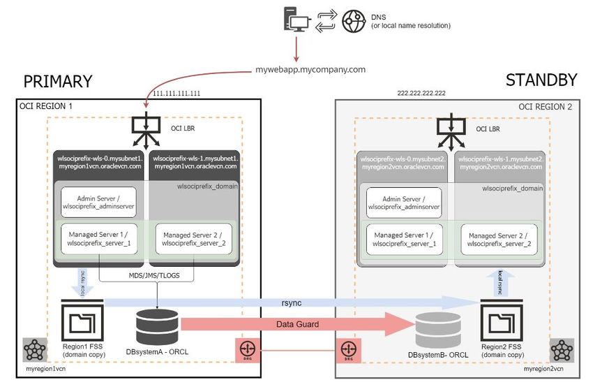
TABLE OF CONTENTS
Purpose Statement                                                                                         1
Disclaimer                                                                                                1
Revision History                                                                                          1
Introduction                                                                                              3
Disaster Recovery Solution for Oracle WLS for OCI                                                         5
    Topology description                                                                                  5
    Assumptions                                                                                           8
          WebLogic Editions                                                                               8
          Authentication                                                                                  8
          Load Balancer                                                                                   8
          Database                                                                                        9
    Requirements                                                                                         10
          Frontend address                                                                               10
          WebLogic Resource Name Prefix                                                                  10
          Network communication between sites                                                            10
          Staging filesystems for the WebLogic config replication                                        10
          Custom files                                                                                    11

Disaster Recovery setup                                                                                  11
    1.    Choose a virtual frontend hostname                                                              11
    2.    Prepare Primary mid-tier for the virtual frontend                                               11
    3.    Setup Secondary Database                                                                       12
          3.1       Option 1) Configuring the Data Guard using OCI Console                               13
          3.2       Option 2) Configuring the Data Guard manually                                        14
    4.    Provision Secondary WLS for OCI on Marketplace                                                 16
    5.    Prepare Secondary mid-tier for the virtual frontend                                            19
    6.    Configure required host aliases                                                                19
    7.    Configure the staging mounts for WebLogic config replication                                   20
          7.1       Option 1) Configure the DBFS mounts for DBFS based method                            21
          7.2       Option 2) Configure the FSS mounts for FSS with rsync method                         23
    8.    Run DR setup script in Primary WebLogic Domain                                                 24
    9.    Run DR setup script in Secondary WebLogic Domain                                               25
    10.   Complete DR configuration when IDCS authentication is used                                     27

Lifecycle procedures                                                                                     32
    Replicating configuration changes                                                                    32
    Switchover                                                                                           36
    Failover                                                                                             38

Best practices                                                                                           38
Conclusion                                                                                               39
Appendix A – Considerations for RAC DB Systems                                                           40
Appendix B – Using Enterprise Manager Site Guard to manage Disaster Recovery44
Appendix C – DB System Backups on manual Data Guard                                                      45
Appendix D – Additional lifecycle operations                                                             47
Appendix E – Additional Best Practices                                                                   54

2   WHITE PAPER | Oracle WebLogic Server for Oracle Cloud Infrastructure Disaster Recovery | Version 3
    Copyright © 2021, Oracle and/or its affiliates | Public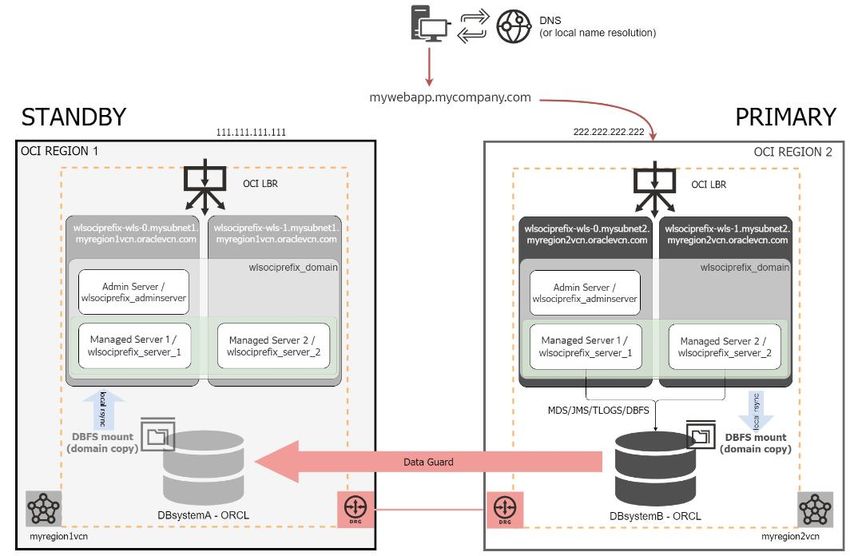
INTRODUCTION
Oracle’s Maximum Availability Architecture (MAA) is the best practices blueprint for data protection and availability of
Oracle products (Database, Fusion Middleware, Applications) deployed on on-premises, private, public, or hybrid clouds.
Implementing Oracle’s Maximum Availability Architecture best practices is one of the key requirements for any Oracle
deployment. Oracle WebLogic and Oracle Databases include an extensive set of high availability features, such as
process death detection and restart, clustering, server migration, clusterware integration, GridLink, load balancing,
failover, backup and recovery, rolling upgrades, and rolling configuration changes, which protects application deployments
from unplanned downtime and minimize planned downtime.

Oracle WebLogic Server for Oracle Cloud Infrastructure (Oracle WLS for OCI) is a Platform as a Service (PaaS)
computing platform solution provisioned via Oracle Marketplace that allows you to create your Java Enterprise Edition
(Java EE) application environment in Oracle Cloud Infrastructure very quickly. In a typical Oracle WLS for OCI
deployment, the application data (such as application-specific schemas, jms stores etc.) is stored in a database. Oracle
WLS for OCI can be configured as a JFR-enabled domain, to support the Oracle Application Development Framework
(ADF), and to use Oracle Fusion Middleware Control console for the administration and monitoring. In this case, WebLogic
uses the database to store the required schemas (like Oracle Platform Security Services information). For transactional
consistency and simplified administration reasons, application data and WebLogic specific schemas are typically stored
in the same database.

Any critical system needs protection from unforeseen disasters and natural calamities. This protection is also required for
systems deployed in the Cloud, like Oracle WLS for OCI. It needs to address front-end access (like load balancer based
front-end host names), the middle tier (Oracle WebLogic) and the data tier (Database Cloud Service). The solution
involves setting up a standby system at a geographically different Oracle Cloud data center than the production site.
Although the standby system may have fewer services and resources compared to the production site, Oracle
recommends running a mirror configuration with the same capacity. The standby system is normally in a passive mode
and is activated when the primary site becomes unavailable. This deployment model is sometimes referred to as an
active-passive model. This model is usually adopted when the two sites are connected over a WAN and network latency
does not allow clustering across the two sites.

Oracle WLS for OCI Disaster Recovery provides the best Recovery Time Objective (RTO) and Recovery Point
Objective (RPO) by utilizing high availability and disaster protection capabilities provided by Oracle Fusion Middleware
and Oracle Database. While there are some unique considerations to a cloud disaster recovery (DR) configuration, it
follows the same Oracle MAA best practices as any Oracle Fusion Middleware (FMW) and Oracle Database deployment.
This Oracle MAA blueprint details Oracle MAA Best Practices and provides a procedural overview for deploying DR for
Oracle WLS for OCI. The Oracle WLS for OCI Disaster Recovery solution is achieved by replicating the configuration files
of the Oracle WebLogic Server domain and the runtime and metadata in the database used. The application may require
additional configuration files to be replicated. Options are provided in this paper to suit different application paradigms.
Disaster protection for Oracle Database Cloud Service used by Oracle WLS for OCI is provided through Oracle Data
Guard.

3   WHITE PAPER | Oracle WebLogic Server for Oracle Cloud Infrastructure Disaster Recovery | Version 3
    Copyright © 2021, Oracle and/or its affiliates | Public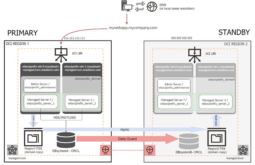
This paper is intended for a technical audience having knowledge of Oracle Cloud Infrastructure, Oracle WebLogic
Server, Oracle Database, Data Guard, and Oracle Database backup and recovery.

4   WHITE PAPER | Oracle WebLogic Server for Oracle Cloud Infrastructure Disaster Recovery | Version 3
    Copyright © 2021, Oracle and/or its affiliates | Public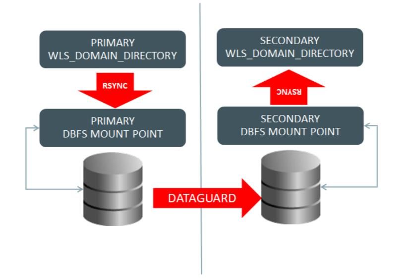
DISASTER RECOVERY SOLUTION FOR ORACLE WLS FOR OCI
Topology description
The Disaster Recovery solution for Oracle WLS for OCI is an active-passive model. There is a primary system consisting on
an Oracle WLS for OCI domain, load balancer, and Oracle Cloud Infrastructure DB system in one region, and a secondary
Oracle WLS for OCI domain, load balancer, and Oracle Cloud Infrastructure DB system in a different region. This same
topology may be implemented in the scope of a single Oracle Cloud Data Center with multiple availability domains although
it is strongly recommended to use different regions for maximum Disaster recovery protection.
The primary and secondary Oracle Cloud Infrastructure DB Systems are configured with Data Guard. Relying on Data Guard
features, all the changes applied to primary database are replicated to secondary database (which acts as the “standby”
database).
The secondary Oracle WebLogic Server domain is a replica of the primary domain, using the same name, schemas,
passwords, etc. but pointing to the secondary database. This document provides the steps to create and configure this
secondary Oracle WebLogic Server domain.
On the frontend, there is a unique name configured to access the applications running in the system. This “virtual” frontend
name will point to the IP of the OCI Load Balancer of the primary site. In case of a switchover, this frontend name is updated
to point to the IP of the OCI Load Balancer of the secondary site. It always must point to the LBR IP of the site that has the
primary role in each time.
Figure 1 Oracle WebLogic for OCI disaster recovery topology
In normal business operation, the standby database is a physical standby. It either is in mount state, or opened in read-only
mode (when Active Data Guard is used). It receives and applies redo from primary, but cannot be opened in read-write. For
some actions, during the DR setup and lifecycle steps described in this document, the standby database will be converted to
a snapshot standby. A snapshot standby database is a fully updateable standby database created by converting a physical
standby database into a snapshot standby database. A snapshot standby database receives and archives, but does not
apply, redo data from a primary database. All the changes performed to a snapshot standby are discarded when the standby
is converted again into physical standby.
All the information that resides in the database (OPSS information, custom schemas, TLOGs, JDBC persistent stores, etc.) is
automatically replicated to the secondary site by Data Guard.
The WLS domain configuration, which is located in the local filesystem in each site, needs to be replicated from primary to
secondary also. This replication is required during the initial DR setup, and also during the system’ s lifecycle, when a
configuration change is performed in the primary domain. Oracle supports two different approaches to perform this
WebLogic domain configuration replication: DBFS (Oracle Database File System) based method and OCI File Storage Service
(FSS) with rsync method. Both methods use the same topology and similar mechanics. The difference resides in how the
information is transferred from primary to secondary:
In the DBFS based method, a copy of the domain configuration is replicated to the secondary site via Data Guard.
A DBFS mount is used as an assistance (or “staging”) filesystem. A DBFS mount is a filesystem that resides in the
5 WHITE PAPER | Oracle WebLogic Server for Oracle Cloud Infrastructure Disaster Recovery | Version 3
Copyright © 2021, Oracle and/or its affiliates | Public
database, and can be mounted like an NFS mount. The primary domain configuration is copied to that DBFS
          mount, and this is automatically replicated to standby via the underlying Data Guard. In the secondary site, the
          same DBFS mount can be mounted from the secondary db by the secondary midtiers, and then, the domain config
          is copied from the DBFS mount to the secondary domain. This whitepaper provides a script that automatizes this
          process in primary and in standby.
          This method takes advantage of the robustness of the Data Guard replica. It can be used in any scenario, and it is
          strongly recommended for DR scenarios that have medium or high latencies between regions.

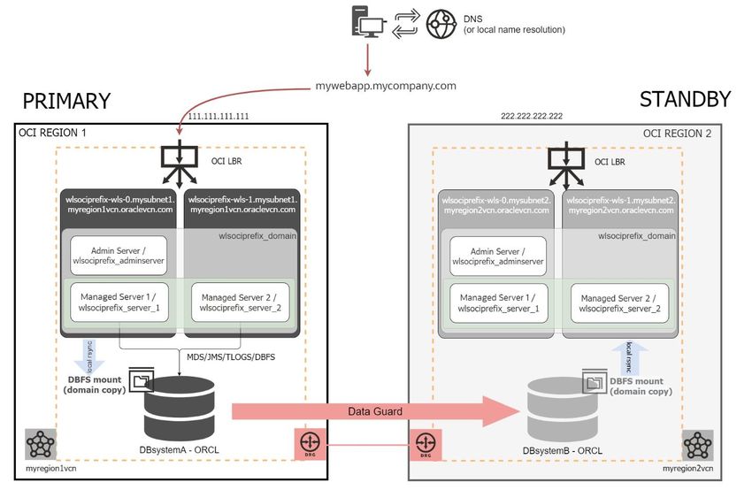
Figure 2 Complete WLS for OCI DR topology using DBFS based method for WLS Domain config replication

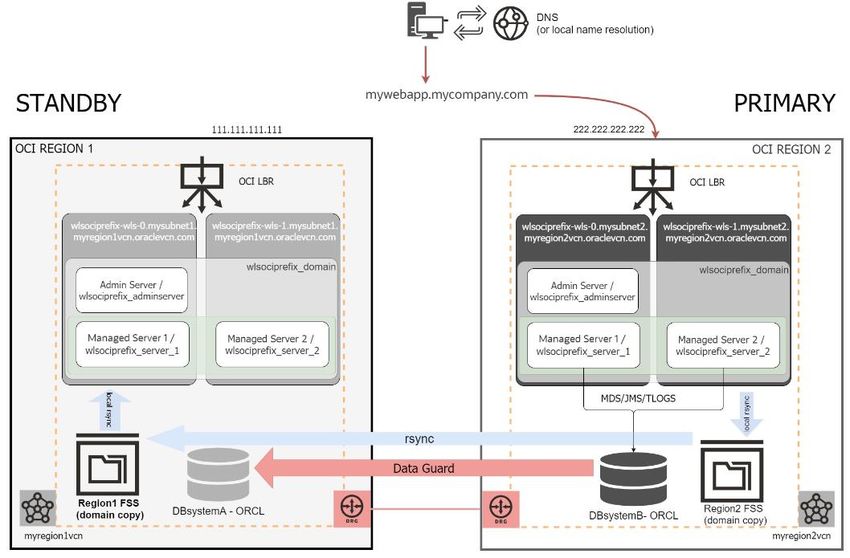
Figure 3 DBFS based method for WLS Domain config replication flow diagram

6   WHITE PAPER | Oracle WebLogic Server for Oracle Cloud Infrastructure Disaster Recovery | Version 3
    Copyright © 2021, Oracle and/or its affiliates | Public
In the OCI File Storage Service (FSS) with rsync method, the domain configuration is transferred to the
secondary site using direct rsync between two file systems, one in primary and another in standby. This approach
uses, like the DBFS one, a filesystem as an intermediate “staging” point. For this, an FSS (File Storage Service)
mount is used in each region. To replicate the primary domain config, the WLS domain is copied first to the
local/staging FSS mount, and then, via rsync, to the remote FSS mount. Then, in secondary, the domain
configuration is copied from the secondary FSS to the secondary domain directory. This whitepaper provides a
script that automatizes this process in primary and standby.
This method is recommended only when the latency between the datacenters is low and the connection is reliable.
Figure 4 Complete WLS for OCI DR topology using OCI FSS with rsync method for WLS Domain config replication
Figure 5 OCI FSS with rsync method for WLS domain config replication flow diagram
7 WHITE PAPER | Oracle WebLogic Server for Oracle Cloud Infrastructure Disaster Recovery | Version 3
Copyright © 2021, Oracle and/or its affiliates | PublicThe DBFS approach provides better retry logic and a more resilient behavior than FSS with rsync across regions. However
the FSS with rsync approach is easier to maintain and configure.
Regardless which method is used to replicate the domain configuration, note that if the standby database is shutdown
during normal business operation, it will not receive updates from primary and it will become out-of-sync. This can result in
a data loss if a switchover needs to be performed. Thus, it is not recommended to have the standby database stopped
during normal business operation. The standby midtier hosts can be stopped to reduce billing, however, the WLS domain
configuration changes that are replicated from the primary site will not be pushed to the secondary domain configuration if
they are not started. In case of a switchover event, the RTO is increased if the midtier hosts need to be started and
synchronized with primary changes. Oracle recommends to have the secondary midtier hosts up (with manager servers
stopped).
Assumptions
The following consideration are key aspects for the WebLogic Cloud Disaster Recovery setup:
WebLogic Editions
There are three different WebLogic on OCI editions:
Oracle WebLogic Server Standard Edition
Oracle WebLogic Server Enterprise Edition
Oracle WebLogic Suite
See WebLogic Chapter in Licensing Information User Manual for more information about their features. The use of Oracle
WebLogic Server GridLink data sources, known as Active GridLink for RAC, is an entitlement available only as part of
licensing WebLogic Suite. The other editions do not include Active Gridlink so they use Multi Datasources to connect to a
RAC database. It is an MAA best practice to use GridLink datasources when RAC is used.
This document applies to Oracle WebLogic Suite Edition and to WebLogic Enterprise Edition, except when Oracle RAC DB
System is used. When the database is a RAC DB System, this document assumes that Oracle WebLogic Suite Edition is
used. This DR setup supports only that edition for RAC scenarios because it is the only edition that uses GridLink
datasources.
Authentication
Oracle WLS for OCI can be provisioned with the option "Enable Authentication using Identity Cloud Service". In that case, it
uses Oracle Identity Cloud Service (IDCS) to authenticate users in the domain, instead of using the default Oracle WebLogic
Server Identity Store. This adds additional components to the system, like the Cloud App Gateway agents and Identity Cloud
Services.
This document addresses WLS for OCI systems that use the default Oracle WebLogic identity store, and also the
implications of using IDCS authentication for WLS for OCI in context of a DR event. Notice, however, that IDCS’s own
disaster protection is out of the scope of this paper1.
This does not preclude customers from customizing the WebLogic identity store to use another external LDAP (as long as
WebLogic supports it for OCI). As long as the WebLogic provider's configuration resides in the domain config, it will be
replicated to the standby domain. If the standby WebLogic system is able to reach to the configured external LDAP url, it can
be used. Note that the DR solution for any external LDAP service is out of the scope from this WLS DR whitepaper, and
should be provided by the specific LDAP product.
Load Balancer
The Disaster Recovery solution assumes that the Oracle WLS for OCI is configured with an OCI Load Balancer. A load
balancer is mandatory when the cluster has more than one server, so the incoming requests can be balanced between them.
1 Contact IDCS support to check the IDCS Disaster Recovery solution availability in your region and to get details on how IDCS itself is protected against
disasters.
8 WHITE PAPER | Oracle WebLogic Server for Oracle Cloud Infrastructure Disaster Recovery | Version 3
Copyright © 2021, Oracle and/or its affiliates | PublicThe default Load Balancer that is created during the Oracle WLS for OCI provisioning is an OCI Load Balancer. Depending on
your network topology, it can be public or private.
A public OCI load balancer is regional in scope. If your region includes multiple availability domains, it creates a primary load
balancer and a standby load balancer, both in the same region but each one in a different availability domain. If the primary
load balancer fails, the public IP address used for incoming traffic switches to the standby load balancer that is in the same
region. The service treats the two load balancers as equivalent and you cannot specify which one is "primary". This way, the
load balancer provides local (inside a region) high availability for the load balancer layer.
The same topology will exist in the secondary region: the OCI LBR in the secondary domain will have one primary load
balancer in one of the availability domains of the secondary region and another one in the other availability domain of the
secondary region.
Similar topology is used in a private OCI load balancer, which can be used to isolate your system from internet, although it
only uses one subnet to host primary and standby. It can be regional or AD-specific, depending on the scope of the subnet it
uses. If the subnet is regional and the region contains multiple availability domains, primary and standby load balancers are
located in different ADs. If the subnet is AD-specific, primary and standby are in the same AD (in this case it has no failover
capability in response to an availability domain outage).
See documentation for OCI Load Balancing for additional details.
This configuration is sufficient for the disaster recovery configuration. No config replication is required between primary and
secondary region’s Load Balancers, as each one needs to route only to its local WebLogic cluster. Only in case that the
default configuration is modified in primary site load balancers (for example, by adding listeners, backends, or certificates),
should it be manually modified on the secondary region load balancer.
Database
During the Oracle WLS for OCI provisioning, you can choose to associate it to an existing database. The usage of an Oracle
Cloud Infrastructure Database System along with Oracle WebLogic Cloud is the most common scenario:
Database is mandatory when customers want to use features like Fusion Middleware Control Console to monitor,
configure and manage the domain, OPSS Security, ADF Framework, etc. (known as “JFR-enabled” domains.).
It is also an MAA best practice to use a database for any persistent information stored by the WebLogic Server
domain, like JMS persistent stores or JTA logs. Especially in Disaster Recovery topologies, where this information
can be automatically available in the secondary site in case that secondary becomes the primary thanks to the Data
Guard replication.
In addition, application’s runtime data is usually stored in custom schemas in the database.
Per the above, the Disaster Recovery solution assumes that the Oracle WLS for OCI is configured with an Oracle Cloud
Infrastructure DB System and this document applies to that scenario. This enables the usage of some useful database
features like Oracle Database File System (DBFS). Along with Data Guard, DBFS is used during the initial disaster recovery
setup and during the lifecycle management, to replicate the WebLogic Server domain configuration from primary to
secondary domain in the DBFS based method.
When the DB System used by WLS for OCI is a RAC Database (this is, when it has more than 1 db node), see the Appendix A
– Considerations for RAC DB Systems for specific instructions and best practices.
Note that Oracle Autonomous Processing (ATP) is out of the scope of this document. Although ATP (ATP-D) now supports
cross-region Data Guard, it does not provide a number of features required for PaaS DR, (like snapshot standby conversion,
dgbroker access and others) Oracle ATP can’t be used in WLS for OCI disaster recovery topologies.
9 WHITE PAPER | Oracle WebLogic Server for Oracle Cloud Infrastructure Disaster Recovery | Version 3
Copyright © 2021, Oracle and/or its affiliates | PublicRequirements
The following requirements are key aspects for the WebLogic Cloud Disaster Recovery setup:
Frontend address
The access from clients to the system must be agnostic to the site that is being used. To accomplish this, the frontend
address name used to access the system must be unique and point always to the system that is the primary in each
moment. This name is usually referred to as “virtual frontend” or “vanity url”.
It is possible to reuse the existing system’s front-end host name address (if such exists already) as the virtual frontend for
disaster protection, i.e. if the original system was using mywebapp.example.com as the vanity url for primary, this same
virtual hostname can be mapped to the secondary system after a switchover.
Appropriate DNS services (Oracle Cloud DNS, other commercial DNS, local DNS or local hosts resolution) need to be used for
the frontend name to be mapped to either site. Later in this document it is explained how to configure WebLogic Cloud to
use the virtual frontend name.
WebLogic Resource Name Prefix
When you provision a WLS for OCI, you need to provide the “Resource Name Prefix”. This property, limited to 16 chars, is
used to construct the names of all the resources: the WebLogic Server domain name, the cluster name, the WebLogic
servers, the VMs’ hostnames, etc.
This property must be set to the same value in the primary and secondary WLS for OCI systems, so that both systems
have the same name for the WebLogic resources. Using the same name guarantees consistency and is required for example
for the recovery of JMS messages and Tlogs. It also simplifies customizations and operations in both sites.
There is no restriction to use the same “Resource Name Prefix” in multiple instances in the same Cloud tenancy, as long as
they are created in different regions and/or compartment. Each instance is shown only in its specific region and
compartment.
Network communication between sites
The primary and secondary databases need to communicate with each other over their listener port for redo transport.
Middle tier hosts need to communicate with the remote database (to the listener port) for the initial setup also.
When using the FSS with rsync method approach, each WebLogic Administration host needs to communicate with the
remote WebLogic Administration host for the rsync copy (to the ssh port).
This communication can happen over an Internet Gateway (Oracle Net’s traffic is encrypted). As a better approach, the
communication between primary and standby sites can be through internal networks, by using Dynamic Routing
Gateway and this is the recommended approach (refer to the Dynamic Routing Gateway documentation for additional
details on the network configuration.) Depending on which method is used, the appropriate ingress rules need to be
enabled. Security rules are configured in the Security Lists for each Virtual Cloud Network (in the OCI console, Core
Infrastructure > Networking Section > Virtual Cloud Network). More information about this is available in Security Rules
section on the OCI documentation.
The amount of data replicated depends on the redo generated by the primary database, and this is directly related with
application load, its transactionality, concurrency, etc. The overhead of the DBFS for replicating configuration is typically
irrelevant compared to the runtime data that Data Guard synchronizes. To ensure a timely delivery of the redo log files to
the secondary database, a suitable network connection between the primary site and the secondary site must be provided.
Oracle Cloud Infrastructure regions are interconnected with high-bandwidth, fault-tolerant networks achieving ≥ 99.95
percent reliability (≤5 packets lost in 10,000), which provides also a consistent latency. See Oracle Cloud Infrastructure Data
Center Regions for more details.
Staging filesystems for the WebLogic config replication
As explained before, two different approaches are included in this document to automatically replicate the WLS domain
configuration from primary to secondary: DBFS based method and FSS with rsync method. Both methods require an
assistance filesystem to be mounted in the WebLogic hosts: a DBFS mount in the DBFS based method, and a FSS mount in
the FSS with rsync method. In the next sections of this document, more details and specific instructions are provided to
configure the staging filesystem in each case.
10 WHITE PAPER | Oracle WebLogic Server for Oracle Cloud Infrastructure Disaster Recovery | Version 3
Copyright © 2021, Oracle and/or its affiliates | PublicCustom files
Most of the WebLogic Server domain configuration that WebLogic Cloud uses is synced initially across sites with the
following considerations:
Each WebLogic system will maintain the original JDBC URLs used to connect to their local DB even after the DR set
up has completed. Only the schema prefix will be altered so that both locations point to the same schemas (primary
schemas).
All the configuration under weblogic_domain_name/config is automatically distributed, by the Weblogic
Infrastructure, to the other nodes in the same site by the WebLogic cluster features.
Custom application deployments (ear/war files, deployment plans, etc.) and everything residing under the
Administration Server WLS domain directory (except temp data) is synced initially across sites using the procedures
described in this paper.
In the next sections of this document, more details are provided about how the configuration replica is performed. In case
that customer has any other data residing in other node’s or outside the domain directory for the WebLogic Administration
Server, it will have to be manually copied to the secondary location.
DISASTER RECOVERY SETUP
In this document it is assumed that, as starting point, the primary site, consisting of an OCI DB system, an Oracle WLS for
OCI system, and the Load Balancer (OCI LBR) is live. The secondary DR configuration, residing in a geographically remote
site, will be created for this existing primary system.
Since the primary may already be running in production, the DR configuration process is designed to cause minimum
downtime (only the modification of the frontend address requires WebLogic server restarts).
This is a summary of the steps for the set up process:
1. Choose a virtual frontend hostname
2. Prepare Primary mid-tier for the virtual frontend
3. Setup Secondary Database
4. Provision Secondary WLS for OCI on Marketplace
5. Prepare Secondary mid-tier for the virtual frontend
6. Configure required host aliases
7. Configure the staging mounts for WebLogic config replication
8. Run DR setup script in Primary WebLogic Domain
9. Run DR setup script in Secondary WebLogic Domain
1. Choose a virtual frontend hostname
By default, when an Oracle WLS for OCI instance is created, the Load Balancer provisioned listens on a specific frontend IP
address and no frontend name is provided nor configured in the system. Primary site LBR listens in one frontend IP, and
secondary site LBR will listen in another frontend IP.
In a disaster recovery topology, the clients must access the system using a “Cloud region or Data Center” agnostic
hostname: they should point to a single frontend name, that will be resolved to the LBR frontend IP where primary is active
at that moment. You have to choose a virtual frontend hostname for the system (for example,
“mywebapp.mycompany.com”) and make it resolvable externally. If you already have a frontend hostname configured to
access to the primary system, you can reuse it for the DR configuration.
To externally resolve this frontend hostname, you must register it any formal public DNS (alternatively, you can add it to the
client’s local hosts file). To resolve the virtual hostname in the scope of the WebLogic virtual machines, local hosts file will be
used.
To determine the frontend IP of the LBR in your system, login into the OCI Console, navigate to Load Balancers section, click
on your LBR and look for the IP address that the LBR listens on.
2. Prepare Primary mid-tier for the virtual frontend
You need to perform some actions in the primary mid-tier to prepare it for the DR configuration.
11 WHITE PAPER | Oracle WebLogic Server for Oracle Cloud Infrastructure Disaster Recovery | Version 3
Copyright © 2021, Oracle and/or its affiliates | Publica) Add the frontend name and IP to the /etc/hosts file in all primary mid-tier hosts.
As root user, edit the /etc/hosts file and map the primary LBR IP to the virtual frontend name. Repeat in all primary
WebLogic hosts. Example:
[oracle@wlsmkpl1-wls-0 ~]$ more /etc/hosts
127.0.0.1 localhost localhost.localdomain localhost4 localhost4.localdomain4
::1 localhost localhost.localdomain localhost6 localhost6.localdomain6
…
# Frontend
111.111.111.111 mywebapp.mycompany.com
b) Configure the frontend name as cluster frontend.
Login in the WebLogic Console of your instance and:
Navigate to Environment > Clusters and select the cluster
Go to Configuration > HTTP.
Set the Fronted host to the frontend name (example “mywebapp.mycompany.com”).
Be sure that the Frontend ports for HTTP and HTTPS are correctly configured with values.
Save and activate. A cluster restart is required for this change to be effective.
Figure 6 Cluster frontend host configuration
c) Update t3/rmi urls (if used) with cluster syntax
The urls used for RMI invocations in the WebLogic cluster need to be agnostic also to the IPs or hostnames used by
each site. Instead of using the host:port,host:portJNDI urls syntax, change them to use the cluster syntax. The
cluster syntax is as follows: cluster:t3://cluster_name.2
Similarly, any other custom JNDI urls used in the system should also be updated so that when a switchover/failover
occurs, the urls are valid also in the secondary site
3. Setup Secondary Database
The secondary database is created as a Data Guard physical standby of the primary database. There are 2 options to do this:
one is to use the OCI Console to enable Data Guard (referred in this document as “automated Data Guard”), and the other
2 Obviously, this is feasible only for intra-domain invocations. T3/rmi clients that are external to the domain will not be able to use this approach and will have to use
the appropriate DNS mapping of the host:port list when switching to the secondary site. A TCP load balancer can be used for the JNDI InitialContext retrieval, but
subsequent requests from JMS clients will connect to the host:port directly, so the DNS mapping to secondary site IPs is required also in this case.
12 WHITE PAPER | Oracle WebLogic Server for Oracle Cloud Infrastructure Disaster Recovery | Version 3
Copyright © 2021, Oracle and/or its affiliates | Publicoption is to manually create and configure the standby database with dgmgrl commands (referred in this document as
“manual Data Guard”).
The recommended approach is to configure the Data Guard using the OCI Console. This way, it is integrated with the OCI
Console User Interface and allows you to use the Console to manage Oracle Data Guard associations in your DB system. It
also provides out of the box configuration for backups in the Data Guard. Follow the point Option 1) Configuring the Data
Guard using OCI Console to enable the Data Guard using the OCI Console.
If for any reason the feature to enable Data Guard is not available for your case (please refer to the Oracle Cloud
Infrastructure Documentation Using Oracle Data Guard for checking the availability of the Data Guard across regions feature
in each DB Systems flavor/edition), you can still configure the Data Guard manually using scripts provided in this
whitepaper. Follow steps described in Option 2) Configuring the Data Guard manually for this.
3.1 Option 1) Configuring the Data Guard using OCI Console
When enabling Data Guard using the OCI Console, the secondary DB system is automatically provisioned and
configured as physical standby when you click on Enable Data Guard in the primary DB System. There are some
requirements for this, for example: both DB systems will be in the same compartment, both DB Systems will be the same
shape type, if the DB Systems in different regions must be connected via remote VCN peering, etc. See Using Oracle Data
Guard in Oracle Cloud Infrastructure Documentation for more details about these requirements.
To enable Data Guard to primary database, login to OCI Console, navigate to the primary DB System, and click in the primary
database. You can enable Data Guard in the section “Data Guard Associations”. Most of the configuration properties of the
secondary DB System (like version, DB name, etc.) are predefined because they are inherited from primary, but you need to
provide some configuration properties. The following table provides examples and requirements for these properties:
DB SYSTEM EXISTING PRIMARY DB SYSTEM SECONDARY DB SYSTEM REQUIREMENT FOR
CONFIGURATION / EXAMPLE / EXAMPLE AUTOMATED DG
PROPERTY
Oracle Cloud XXXX / paasmaa YYYY / paasmaa must be the same
Tenancy
Compartment XXXX / wlsdr XXXX / wlsdr must be the same
Region XXXX / Ashburn YYYY / Phoenix must be different
(recommended
different regions for DR)
Availability XXXX / efEXT:US-ASBURN- YYYY / efXT:PHX-AD-1 must be different
Domain AD1
DB System Name XXXX / drdbwlmp1a YYYY / drdbwlmp1b must be different
Shape XXXX / VM.Standard2.1 XXXX / VM.Standard2.1 must be the same
Virtual Cloud XXXX / wlsdrvcn1ash YYYY / wlsdrvcn1pho must be different
network (expected different
regions, connected via
remote VCN peering)
Client subnet XXXX / wlsdrvcn1ashAD1 XXXX / wlsdrvcn1phoAD1 must be different
(expected different
regions, connected via
remote VCN peering)
Hostname Prefix XXXX / drdbwlmp1a YYYY / drdbwlmp1b must be different
Administrator XXXX / acme1234# XXXX / acme1234# must be the same
password
13 WHITE PAPER | Oracle WebLogic Server for Oracle Cloud Infrastructure Disaster Recovery | Version 3
Copyright © 2021, Oracle and/or its affiliates | Public3.2 Option 2) Configuring the Data Guard manually
It is required to configure Data Guard manually when it is not possible to use the same tenancy for primary and standby or
when the automated Data Guard option provided by OCI is not enabled for the DB flavor and/or locations involved in the DR
configuration. In this case, the secondary database must be first provisioned as a regular DB System and then it will be
configured as the standby by executing some setup scripts provided in this document, as explained in these steps:
3.2.1 Provisioning Secondary Database
Note: In case that the Data Guard has been enabled using the OCI Console, these steps must be skipped and you can continue with
section 4 Provision Secondary WLS for OCI on Marketplace.
When configuring the Data Guard manually, you first need to provision the secondary database, using the same Database
name, PDB name, release, patch level and edition used in primary. This may require patching the primary system (especially
if it has been running for a long time) before creating the standby. Oracle recommends using the same Compute Shape and
Storage Size that are used for primary. Follow the steps in the Cloud DB System documentation to provision the required
Database System for the standby datacenter.
The following table provides examples and requirements for the properties that need to be used in the standby DB System
creation process:
DB SYSTEM EXISTING PRIMARY DB SYSTEM SECONDARY DB SYSTEM REQUIREMENT FOR DR
CONFIGURATION / EXAMPLE / EXAMPLE
PROPERTY
Oracle Cloud XXXX / paasmaa YYYY / paasmaa can be different
Tenancy
Compartment XXXX / wlsdr YYYY / wlsdr can be different
Region XXXX / Ashburn YYYY / Phoenix must be different
(recommended
different regions for DR)
Availability XXXX / efEXT:US-ASBURN- YYYY / efXT:PHX-AD-1 must be different
Domain AD1
DB System Name XXXX / drdbwlmp1a YYYY / drdbwlmp1b must be different
Shape XXXX / VM.Standard2.1 XXXX / VM.Standard2.1 must be the same
Total node count N/1 N/1 must be the same
Oracle Database EE, EE-HP or EE-EP EE, EE-HP or EE-EP must be the same
Software edition
/ EE-EP / EE-EP
Available XXXX / 256 XXXX / 256 must be the same
storage
License type LI, BYOL / BYOL LI, BYOL / BYOL can be different
SSH public key XXXX YYYY can be different
Virtual Cloud XXXX / wlsdrvcn1ash YYYY / wlsdrvcn1pho must be different
network (expected different
regions, recommended
14 WHITE PAPER | Oracle WebLogic Server for Oracle Cloud Infrastructure Disaster Recovery | Version 3
Copyright © 2021, Oracle and/or its affiliates | Publicconnect via remote VCN
peering)
Client subnet XXXX / wlsdrvcn1ashAD1 XXXX / wlsdrvcn1phoAD1 must be different
Hostname Prefix XXXX / drdbwlmp1a YYYY / drdbwlmp1b must be different
Database Name XXXX / ORCL XXXX / ORCL must be the same
Database XXXX / 19c XXXX / 19c must be the same
Version
PDB name XXXX / PDB1 XXXX / PDB1 must be the same
Administrator XXXX / acme1234# XXXX / acme1234# must be the same
password
Enable X / Checked Y / unchecked must be disabled in
automatic stby
backups
NOTE: The default database instance created on the secondary site will be deleted later as it cannot be used as a Data Guard standby
database. It is created with the same name as primary to get the required lifecycle scripts seeded in the system with the same
configuration as the primary DB
Make sure to apply the required patches to the DB in both locations (primary and secondary) so that to both are at the same
patch level. More precisely, a Data Guard configuration requires a fix for bug 22611167 in 12c versions. Verify if the patch is
applied in both the primary and secondary DB systems, and apply it in case it is not. Latest OCI 12cR2 DB systems have the
patch for this bug pre-installed.
Not for RAC scenarios: see the appendix Appendix A – Considerations for RAC DB Systems
3.2.2 Configuring the Data Guard between primary and secondary
Note: In case that the Data Guard has been enabled using the OCI Console, these steps must be skipped and you can continue with
section 4 Provision Secondary WLS for OCI on Marketplace.
In order to configure the Data Guard manually between the primary and secondary databases, follow these steps.
a) Primary and standby databases in a Data Guard need to communicate each other on the listener port. It is also
needed that each database can reach its own IP on the appropriate listener port. Make sure that the appropriate
ingress rules are defined in each VCN (primary and standby) to allow these connections.
You can verify this communication using nc command (use the public/private IPs depending on your network
topology).
From primary to secondary:
[opc@drdDBa ~]$ nc -vw 5 -z 1521
From secondary to primary:
[opc@drdDBb ~]$ nc -vw 5 -z 1521
Example for correct output:
15 WHITE PAPER | Oracle WebLogic Server for Oracle Cloud Infrastructure Disaster Recovery | Version 3
Copyright © 2021, Oracle and/or its affiliates | Public[opc@drdbb ~]$ nc -vw 5 -z 10.0.0.79 1521
Ncat: Version 7.50 ( https://nmap.org/ncat )
Ncat: Connected to 10.0.0.79:1521.
Ncat: 0 bytes sent, 0 bytes received in 0.07 seconds.
NOTE: Use the public DB System’s IPs in case that primary and secondary sites use Internet Gateway to communicate each other, and
use internal DB System’s IPs in case the communication between primary and secondary VCNs is done internally, using a Dynamic
Routing Gateway.
b) Download the dataguardit_primary.sh script and upload to the primary Database node.
c) Open the script as oracle user, read its instructions and customize the variables explained in its initial section.
Once customized, execute the script as oracle user. As an output, it will create a tar file that needs to be copied
from primary to standby. The location where the tar is created can be customized with a script variable.
d) Copy the tar file to the standby database node. Make sure that oracle user has read rights on the file. If It was
uploaded with opc user, to make it readable by others. Example:
[opc@drdDBb ~]$ chmod o+r /tmp/ORCL.GZ
e) Download the dataguardit_standby_root.sh script and upload to the secondary Database node.
f) Open the script as root user, read its instructions and customize the variables explained in its initial section.
g) Once customized, execute the script as root user. The script will delete the existing database instance and will
create a new one duplicating the primary. It will also set up de database listener and configuration required for
Oracle Data Guard broker.
h) Monitor the execution of the script and check for any errors. The script will create a log file
(/tmp/dataguardit_date.log). Check this log for troubleshooting information.
The script can be executed again in case of failure (it will do the cleanup of any previous failed executions).
i) After the script completes, enter the Data Guard Broker CLI from the primary system to check the configuration
(redo apply may take some time to catch up):
DGMGRL> show configuration
Configuration - ORCL_lhr2bb_ORCL_fra22g_12:09:
Protection Mode: MaxPerformance
Members:
ORCL_lhr2bb - Primary database
ORCL_fra22g – Physical standby database
Fast-Start Failover: Disabled
Configuration Status:
SUCCESS (status updated 33 seconds ago)
4. Provision Secondary WLS for OCI on Marketplace
Secondary WebLogic will be created pointing to the secondary DB system, which must be open in snapshot standby mode.
So, before provisioning the secondary WebLogic Cloud, convert standby database to snapshot standby. This will make the
standby database to stop applying changes from primary and be opened in read-write, which is needed to allow the
secondary WebLogic creation. To do this, execute the following as oracle user in the primary DB host:
[oracle@drdbwlmp1a ~]$dgmgrl sys/your_sys_password@primary_db_unqname
DGMGRL> CONVERT DATABASE “secondary_db_unqname” to SNAPSHOT STANDBY;
Converting database "secondary_db_unqname" to a Snapshot Standby database, please wait...
Database "secondary_db_unqname" converted successfully
Then, follow the steps in the Using Oracle WebLogic Server for Oracle Cloud Infrastructure documentation to create the
secondary site WebLogic Cloud system pointing to the secondary DB System.
The Stack Name can be different, but you must use the EXACT same resource name prefix that you used in your primary
location. Oracle recommends that the exact same capacity and compute configuration is used on both primary and standby
locations for the ideal failover/switchover behavior.
16 WHITE PAPER | Oracle WebLogic Server for Oracle Cloud Infrastructure Disaster Recovery | Version 3
Copyright © 2021, Oracle and/or its affiliates | PublicMake sure that the WLS for OCI version and patch level to be provisioned in the secondary location matches the one running
in the primary site.3
The following table summarizes the provisioning wizard options for the set up:
WEBLOGIC CLOUD VALUE IN PRIMARY / EXAMPLE VALUE IN SECONDARY / REQUIREMENT FOR DR
PROPERTY EXAMPLE
Region XXXX / Ashburn YYYY / Phoenix Must be different
Version XXXX / 12.2.1.4.200414.03 XXXX / 12.2.1.4.200414.03 must be the same3
Stack Name XXXX / wlsmkpl1prim YYYY / wlsmkpl1stby can be different
Resource Name XXXX / wlsmkpl1 XXXX / wlsmkpl1 must be the same
Prefix
WebLogic Server XXXX / VM.Standard2.1 XXXX / VM.Standard2.1 must be the same
Shape
WebLogic Server N/2 N/2 must be the same
Node Count
Admin User XXXX / weblogic XXXX / weblogic must be the same
Name
Admin Password XXXX / YYYY / must be the same
(secret OCID) ocid1.vaultsecret.oc1.uk- ocid1.vaultsecret.oc1.eu- password (although the
london-1.amaaaaaaj4…. frankfurt-1.amaa secret OCID could be
different because the
secondary vault will be
in the secondary
region)
WebLogic Server XXXX XXXX must be the same
Instance
Be sure you use the
Configuration
(ports) same ports than in
primary
Network XXXX / wlsdr YYYY / wlsdr can be different
Compartment
VCN XXXX / wlsvcnSite1 YYYY / wlsvcnSite2 must be different
Subnet XXXX / wlsvcnSite1Subnet1 YYYY / wlsvcnSite2Subnet1 must be different
Provision Load Must be checked Must be checked checked in both cases
Balancer
3 WLS for OCI provisioning offers the two latest PSUs, which means that the customer can provision the same PSU in timeframe 3-6 months. If at the moment of
the secondary provisioning the PSU of the primary WLS for OCI is not available in provisioning, the primary WLS for OCI must be patched to the same level as the
newly provisioned secondary site.
17 WHITE PAPER | Oracle WebLogic Server for Oracle Cloud Infrastructure Disaster Recovery | Version 3
Copyright © 2021, Oracle and/or its affiliates | PublicEnable Check or Unchecked Check or Unchecked must be the same
authentication
using IDCS
(if IDCS is checked) XXXX/ XXXX/ must be the same
IDCS host identity.oraclecloud.com identity.oraclecloud.com
domain name
(if IDCS is checked) XXX / 443 XXX / 443 must be the same
IDCS port
(if IDCS is checked) XXXX/ idcs-5e890de5903jr… XXXX/ idcs- must be the same
IDCS tenant 5e890de5903jr…
(if IDCS is checked) XXXX / f88aa64hh8hgd… XXXX / f88aa64hh8hgd… must be the same
IDCS Client ID
(if IDCS is checked) XXXX / uk-london- YYYY / eu-frankfurt- IDCS Client Secret
Secrets OCID for 1.amassshdjhjdf… 1.j7hjhj7jfhfd…. (unencrypted value)
IDCS Client must be the same, but
Secret the OCID of the vault
secret can be different
(created in each
region’s vault)
(if IDCS is checked) XXXX / 9999 XXXX / 9999 must be the same
IDCS Redirect
Port
OCI Policies Unchecked Unchecked For DR topologies it is
recommended to
manually create the
required OCI dynamic
group and policies 4
Provision with Checked Checked Must be the same
JRF (checked)
Database Database System Database System must be the same
Strategy
DB system XXXX / wlsdr XXXX / wlsdr can be different (but
compartment normally the same)
DB system XXXX / wlsvcnSite1 YYYY / wlsvcnSite2 must be different
network (expected different
regions)
DB system XXXX / drdbwlmp1a YYYY / drdbwlmp1b must be different
DB version XXXX / 19 XXXX / 19 must be the same
4 See https://docs.oracle.com/en/cloud/paas/weblogic-cloud/user/you-begin-oracle-weblogic-cloud.html to manually create the dynamic group and policies
18 WHITE PAPER | Oracle WebLogic Server for Oracle Cloud Infrastructure Disaster Recovery | Version 3
Copyright © 2021, Oracle and/or its affiliates | PublicDatabase in the XXXX / ORCL XXXX / ORCL must be the same
system
PDB XXXX / PDB1 XXXX / PDB1 must be the same
Database SYS SYS must be the same
administrator
Database XXXX/ XXXX / must be the same
administrator ocid1.vaultsecret.oc1.uk- ocid1.vaultsecret.oc1.eu- password (although the
password (secret london-1.amaaaaaaj4…. frankfurt-1.amaaaaaaj4y secret OCID could be
OCID) different because the
vault will be in the
secondary region)
NOTE: the Vault service is used only for encrypting and decrypting passwords during the provisioning. It is not used for WebLogic
runtime or lifecycle tasks. You can use the same Vault and secret OCID for provisioning primary and secondary WebLogic Cloud
services or use a different one. In this last case, the secrets OCID that are provided to the provisioning wizard will be different even if
the clear password is the same.
Once the provisioning process completes, the WebLogic servers can be sanity verified.
5. Prepare Secondary mid-tier for the virtual frontend
You need to add the frontend name and IP to the /etc/hosts file in all secondary mid-tier hosts. With root user, edit the
/etc/hosts file and map the SECONDARY LBR IP to the virtual frontend name. Repeat in all secondary WebLogic hosts.
Example:
[oracle@wlsmkpl1-wls-0 ~]$ more /etc/hosts
127.0.0.1 localhost localhost.localdomain localhost4 localhost4.localdomain4
::1 localhost localhost.localdomain localhost6 localhost6.localdomain6
…
# Frontend
222.222.222.222 mywebapp.mycompany.com
You do not need to update the front-end address for the WebLogic secondary cluster as that information will be copied from
the primary WebLogic Domain configuration.
6. Configure required host aliases
The hostnames that are used as listen addresses for the WLS servers in primary need to be valid in the secondary location,
but mapping to the secondary IPs. And the other way around: the hostnames used as listen address for the WLS servers in
secondary need to be valid in the primary location but mapping to the primary IPs. To configure the required alias:
a) First of all, in all the mid-tier hosts (primary and standby), edit the file /etc/oci-hostname.conf as root user and
set PRESERVE_HOSTINFO=3, so the changes implemented in next steps in the /etc/hosts are preserved after node
reboots.
b) Identify the hostnames of each WebLogic hosts in primary and standby where the server listen. To get them, you
can look for the listen addresses in the domain configuration file. For example, in primary domain:
[oracle@wlsmkpl1-wls-0 config]$ cd $DOMAIN_HOME/config
[oracle@wlsmkpl1-wls-0 config]$ grep listen-address config.xml
wlsmkpl1-wls-0.wlsdrvcnlon1ad2.wlsdrvcnlon1.oraclevcn.com
wlsmkpl1-wls-0.wlsdrvcnlon1ad2.wlsdrvcnlon1.oraclevcn.com
wlsmkpl1-wls-1.wlsdrvcnlon1ad2.wlsdrvcnlon1.oraclevcn.com
wlsmkpl1-wls-0.wlsdrvcnlon1ad2.wlsdrvcnlon1.oraclevcn.com
wlsmkpl1-wls-1.wlsdrvcnlon1ad2.wlsdrvcnlon1.oraclevcn.com
And in the secondary domain:
19 WHITE PAPER | Oracle WebLogic Server for Oracle Cloud Infrastructure Disaster Recovery | Version 3
Copyright © 2021, Oracle and/or its affiliates | Public[oracle@wlsmkpl1-wls-0 config]$ cd $DOMAIN_HOME/config
[oracle@wlsmkpl1-wls-0 config]$ grep listen-address config.xml
wlsmkpl1-wls-0.wlsdrvcnfra1ad2.wlsdrvcnfra1.oraclevcn.com
wlsmkpl1-wls-0.wlsdrvcnfra1ad2.wlsdrvcnfra1.oraclevcn.com
wlsmkpl1-wls-1.wlsdrvcnfra1ad2.wlsdrvcnfra1.oraclevcn.com
wlsmkpl1-wls-0.wlsdrvcnfra1ad2.wlsdrvcnfra1.oraclevcn.com
wlsmkpl1-wls-1.wlsdrvcnfra1ad2.wlsdrvcnfra1.oraclevcn.com
You can also use the command “hostname --fqdn” in each midtier host to get its hostname.
c) Edit the /etc/hosts (as root) in all the primary mid-tier nodes and add the hostnames of standby as aliases of
the primary hosts. Each host should have entries as the following:
(shortnames are expected to be the same in primary and stby)
Example of the resulting entries /etc/hosts in primary mid-tier hosts:
[oracle@wlsmkpl1-wls-0 config]$ more /etc/hosts
127.0.0.1 localhost localhost.localdomain localhost4 localhost4.localdomain4
::1 localhost localhost.localdomain localhost6 localhost6.localdomain6
# Frontend
111.111.111.111 mywebapp.mycompany.com
# For WLS DR
10.0.2.10 wlsmkpl1-wls-0.wlsdrvcnlon1ad2.wlsdrvcnlon1.oraclevcn.com wlsmkpl1-wls-0 wlsmkpl1-wls-
0.wlsdrvcnfra1ad2.wlsdrvcnfra1.oraclevcn.com
10.0.2.11 wlsmkpl1-wls-1.wlsdrvcnlon1ad2.wlsdrvcnlon1.oraclevcn.com wlsmkpl1-wls-1 wlsmkpl1-wls-
1.wlsdrvcnfra1ad2.wlsdrvcnfra1.oraclevcn.com
d) In the same way, edit the /etc/hosts (as root) in all the secondary mid-tier nodes and add the hostnames from
primary as aliases of the secondary hosts. Each host should have entries as the following:
Example of the resulting /etc/hosts in secondary mid-tier hosts:
[oracle@wlsmkpl1-wls-1 ~]$ more /etc/hosts
127.0.0.1 localhost localhost.localdomain localhost4 localhost4.localdomain4
::1 localhost localhost.localdomain localhost6 localhost6.localdomain6
# Frontend
222.222.222.222 mywebapp.mycompany.com
# For WLS DR
10.1.2.5 wlsmkpl1-wls-0.wlsdrvcnfra1ad2.wlsdrvcnfra1.oraclevcn.com wlsmkpl1-wls-0 wlsmkpl1-wls-
0.wlsdrvcnlon1ad2.wlsdrvcnlon1.oraclevcn.com
10.1.2.4 wlsmkpl1-wls-1.wlsdrvcnfra1ad2.wlsdrvcnfra1.oraclevcn.com wlsmkpl1-wls-1 wlsmkpl1-wls-
1.wlsdrvcnlon1ad2.wlsdrvcnlon1.oraclevcn.com
NOTE FOR RAC: When the database used is a RAC database, this is a good point to implement the recommendation described in the
Appendix A – Considerations for RAC DB Systems for using a clusterware database service for the PDB rather than the default PDB
service, before continuing with the Disaster Recovery configuration. If you implement that best practice at this point, you can use the
database clusterware service name in the next steps (alternatively, you can use the default PDB services names and implement the
recommendation of using a clusterware service as a post step after DR setup).
7. Configure the staging mounts for WebLogic config replication
This whitepaper provides two different approaches for automating the WLS domain config replica: DBFS based method
and FSS with rsync method. Follow the steps described in the following section for the option used in your Disaster
Recovery topology.
20 WHITE PAPER | Oracle WebLogic Server for Oracle Cloud Infrastructure Disaster Recovery | Version 3
Copyright © 2021, Oracle and/or its affiliates | Public7.1 Option 1) Configure the DBFS mounts for DBFS based method
A DBFS file system is a standard file system interface on top of files and directories that are stored in database table. As it is
stored in the database, a DBFS file system can be used as a shared file system accessible by all the mid-tier hosts.
In WebLogic for OCI DR based on DBFS method, a DBFS mount is used for the initial setup, and also for replicating
WebLogic domain configuration changes. This DBFS filesystem is an assistance filesystem used to sync changes from
primary to standby: the required config files from primary domain are copied to the DBFS filesystem (local copy) and they
are automatically replicated to the standby site thanks to Data Guard underlying replication. In the standy site, the replicated
config files are then copied from the dbfs filesystem to the domain folder. This whitepaper provides an script to automate
this copy in primary and standby.
Note that the DBFS mount is not used for WebLogic runtime, so it is not critical for the service nor the performance.
Figure 7 Using an assistance DBFS file system to replicate WLS domain configuration to secondary site
There is no DBFS mount configured by default in the WebLogic hosts and it needs to be manually configured. This requires
the installation of the Database client and some operating system packages. To perform these actions in each mid-tier host,
follow these steps:
a) Download the DB client from e-delivery and upload it to the mid-tier host (do NOT install it yet). Be sure that you
download the installer version, not the image-based installation. It is recommended to use the latest version.
Here is an example to download the 19.3 db client from e-delivery.
Search for “Oracle Database Client”:
Then select 19.3 and continue:
Then select the database client only:
Click continue and then select the installer version (not the gold image):
21 WHITE PAPER | Oracle WebLogic Server for Oracle Cloud Infrastructure Disaster Recovery | Version 3
Copyright © 2021, Oracle and/or its affiliates | PublicDownload the software and upload it to all the midtier hosts, for example to /u01/install/V982064-01.zip
b) Download the script dbfs_dr_setup_root.sh from the WLS for OCI DR utils and upload it to the mid-tier host. This
script performs the required tasks to get the DBFS mount ready in the host: it installs the db client and its required
operating system packages, it configures the dbfs user and schema in the database, and it mounts the DBFS file
system and creates a cron so the DBFS file system is mounted on host boot.
c) This script requires some input parameters: you need to provide the connection data used to connect to the local
database used by the WLS (i.e.: provide primary PDB connection data in primary site midtier nodes and provide
secondary PDB connection data in secondary site midtier nodes). You can get the local scan name, port and PDB
service name from the datasources of the domain. Then, execute it as root user. Syntax is:
./dbfs_dr_setup_root.sh
NOTE: It is assumed and expected that the standby database is in snapshot standby at this point.
Example to run it primary midtier hosts. You have to provide primary PDB values:
./dbfs_dr_setup_root.sh drdbwlmp1a-scan.wlsdrvcnlon1ad2.wlsdrvcnlon1.oraclevcn.com 1521
PDB1.wlsdrvcnlon1ad2.wlsdrvcnlon1.oraclevcn.com acme1234# /u01/install/V982064-01.zip
Example to run it secondary midtier hosts. You have to provide secondary PDB values:
./dbfs_dr_setup_root.sh drdbwlmp1b-scan.wlsdrvcnfra1ad2.wlsdrvcnfra1.oraclevcn.com
1521 PDB1.wlsdrvcnfra1ad2.wlsdrvcnfra1.oraclevcn.com acme1234# /u01/install/V982064-01.zip
NOTE: If the database is a RAC Database, see Running the dbfs_dr_setup_root.sh in RAC scenarios in Appendix A for specific
instructions
d) You can verify that the DBFS mount is present in the mid-tier host:
[root@ wlsmkpl1-wls-1]# df -h | grep dbfs
dbfs-@PDB1:/ 32G 248K 32G 1% /u02/data/dbfs_root
[root@ wlsmkpl1-wls-1]# ls /u02/data/dbfs_root
dbfsdir
Repeat these steps in all the mid-tier hosts (primary and secondary).
As the result of the execution of this script:
- The db client software is installed in the midtier host, in the folder /u01/app/oracle/client. The required packages
for the db client are installed using yum.
- A user is created in the PDB database for DBFS. The username is dbfsuser, and its password is set to the same sys
password provided as input of the script.
- A DBFS tablespace is created in the PDB database for the DBFS mount (tablespace name is tbsdbfs), and a DBFS
folder (name dbfsdir).
- A new folder is created in the domain, DOMAIN_HOME/dbfs. It contains the wallet is to store the dbfsuser’s
password, and other artifacts needed (tnsnames.ora, sqlnet.ora). This wallet is used by the db client to mount the
dbfs mount in the midtier host.
- The script dbfsMount.sh is also created in DOMAIN_HOME/dbfs. This script is used to mount the dbfs mount in
the midtier. It is also added to the cron on reboot so the script is executed when the machine is rebooted.
- The DBFS mount is mounted in /u02/data/dbfs_root mount point as the folder dbfsdir.
22 WHITE PAPER | Oracle WebLogic Server for Oracle Cloud Infrastructure Disaster Recovery | Version 3
Copyright © 2021, Oracle and/or its affiliates | PublicYou can also read


