Orientation dependent molecular electrostatics drives efficient charge generation in homojunction organic solar cells - Institut Néel
←
→
Page content transcription
If your browser does not render page correctly, please read the page content below
ARTICLE
                  https://doi.org/10.1038/s41467-020-18439-z                 OPEN

                  Orientation dependent molecular electrostatics
                  drives efficient charge generation in homojunction
                  organic solar cells
                  Yifan Dong1,11, Vasileios C. Nikolis2,10,11, Felix Talnack3, Yi-Chun Chin 4, Johannes Benduhn 2,
                  Giacomo Londi 5, Jonas Kublitski 2, Xijia Zheng1, Stefan C. B. Mannsfeld 3, Donato Spoltore2,
                  Luca Muccioli6, Jing Li7, Xavier Blase7, David Beljonne5, Ji-Seon Kim 4 ✉, Artem A. Bakulin 1,
                  Gabriele D’Avino7 ✉, James R. Durrant 1,8 ✉ & Koen Vandewal 9 ✉
1234567890():,;

                  Organic solar cells usually utilise a heterojunction between electron-donating (D) and
                  electron-accepting (A) materials to split excitons into charges. However, the use of D-A
                  blends intrinsically limits the photovoltage and introduces morphological instability. Here, we
                  demonstrate that polycrystalline films of chemically identical molecules offer a promising
                  alternative and show that photoexcitation of α-sexithiophene (α-6T) films results in efficient
                  charge generation. This leads to α-6T based homojunction organic solar cells with an external
                  quantum efficiency reaching up to 44% and an open-circuit voltage of 1.61 V. Morphological,
                  photoemission, and modelling studies show that boundaries between α-6T crystalline
                  domains with different orientations generate an electrostatic landscape with an interfacial
                  energy offset of 0.4 eV, which promotes the formation of hybridised exciton/charge-transfer
                  states at the interface, dissociating efficiently into free charges. Our findings open new
                  avenues for organic solar cell design where material energetics are tuned through molecular
                  electrostatic engineering and mesoscale structural control.

                  1 Department of Chemistry and Centre for Processable Electronics, Imperial College London, London W12 0BZ, UK. 2 Dresden Integrated Centre for Applied

                  Physics and Photonic Materials (IAPP) and Institute for Applied Physics, Technische Universität Dresden, Nöthnitzer Str. 61, 01187 Dresden, Germany.
                  3 Center for Advancing Electronics Dresden (cfaed) and Faculty of Electrical and Computer Engineering, Technische Universität Dresden, Helmholtzstr. 18,

                  01069 Dresden, Germany. 4 Department of Physics and Centre for Processable Electronics, Imperial College London, London SW7 2AZ, UK. 5 Laboratory for
                  Chemistry of Novel Materials, University of Mons, Place du Parc 20, 7000 Mons, Belgium. 6 Department of Industrial Chemistry, University of Bologna, Viale
                  Risorgimento 4, 40136 Bologna, Italy. 7 Université Grenoble Alpes, CNRS, Grenoble INP, Institut Néel, 25 Rue des Martyrs, 38042 Grenoble, France.
                  8 SPECIFIC, College of Engineering, Swansea University, Bay Campus, Swansea SA1 8EN, UK. 9 Institute for Materials Research (IMO-IMOMEC), Hasselt

                  University, Wetenschapspark 1, 3590 Diepenbeek, Belgium. 10Present address: Heliatek GmbH, Treidlerstraße 3, 01139 Dresden, Germany. 11These authors
                  contributed equally: Yifan Dong, Vasileios C. Nikolis. ✉email: ji-seon.kim@imperial.ac.uk; gabriele.davino@neel.cnrs.fr; j.durrant@imperial.ac.uk; koen.
                  vandewal@uhasselt.be

                  NATURE COMMUNICATIONS | (2020)11:4617 | https://doi.org/10.1038/s41467-020-18439-z | www.nature.com/naturecommunications                                1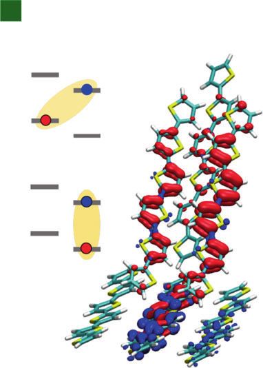
ARTICLE                                                                       NATURE COMMUNICATIONS | https://doi.org/10.1038/s41467-020-18439-z

I
    n contrast to most inorganic semiconductors, the low dielec-                     films leads to efficient and ultrafast charge carrier generation
    tric constants of organic conjugated molecules lead to the                       from excitons, indicating that charge generation happens in the
    formation of tightly bound electron–hole pairs, namely exci-                     bulk of the pristine α-6T. Using specific processing parameters,
tons, upon illumination. As a result, early organic solar cells                      we fabricated films with two molecular orientations, mainly
(OSCs) employing only one absorber material could hardly reach                       standing and mainly lying, and measured an offset of 0.4 eV
a power conversion efficiency (PCE) of 0.1%1. Efficient dis-                           between the ionisation potentials at these two orientations. State-
sociation of excitons could only be achieved by combining two                        of-the-art calculations based on embedded many-body theories
organic semiconductors to form a heterojunction, with one acting                     revealed that this energy offset dictated by intermolecular elec-
as an electron donor (D) and the other one as an electron                            trostatic interactions persists at standing/lying grain boundaries,
acceptor (A)2. An energy level offset between D and A leads to                       where it promotes the formation of low-lying excitations with
the formation of intermolecular charge-transfer (CT) states, an                      hybrid intramolecular/CT character. The population and dis-
electronic state optically coupled to the ground state, in which the                 sociation of these interfacial states provide a rationale for the high
electron resides on A and the hole on D, playing a key role in free                  charge generation quantum yield in α-6T-based HOSCs.
charge carrier generation3,4. Based on the D–A concept, the PCE
for D–A single junction OSCs has increased from 0.1% to over
18%5. This efficiency improvement has resulted from multiple                          Results
factors, ranging from material synthetic design, dielectric con-                     Device performance. Being one of the archetypal organic semi-
stant tuning, interface modification, morphological engineering                       conductors, α-6T has been employed as an electron-donating
etc6–9. However, a downside of this approach is that the D–A                         material and paired with various fullerene and non-fullerene
energy offset also induces significant voltage losses, which limit                    acceptors in OSCs16,17. Here, we test the charge generation effi-
the highest achievable open-circuit voltage (VOC)10. Moreover,                       ciency in α-6T by fabricating HOSCs, where α-6T itself is
optimisation of the blend morphology, finding the best balance                        expected to facilitate photon absorption and charge generation.
between exciton diffusion length and efficient charge transport, as                   The device was fabricated at room temperature by evaporating an
well as preserving this morphology over time, has always been                        α-6T layer between the bottom (indium tin oxide, ITO) and the
challenging11,12. Therefore, fabricating single material devices, as                 top contact (silver, Ag). BPhen was also inserted as the cathode
homojunction OSCs (HOSCs), remains as a highly attractive                            buffer layer (BL), alone or combined with other BL materials
alternative, which offer the potential for relatively easy processing                (Rubrene, C545T, DBzA, TCTA, TPBA, TBPe, TPBI—chemical
and morphology control, and could also lead to high                                  names are given in Supplementary Table 1) that are commonly
photovoltages.                                                                       used in OSCs and organic light emitting diodes (Fig. 1a)20,21. The
   Rare examples of such devices mostly rely on combining D and                      selection of the BLs adjacent to α-6T was based on their lowest
A moieties inside a single chemical entity as a large molecule or a                  unoccupied molecular orbital (LUMO) energy, being comparable
copolymer with a D–A architecture13,14. However, the complexity                      to that of α-6T (Supplementary Table 1), and their use focuses on
in synthesis and processing, as well as ultrafast recombination                      the improvement of contact selectivity and device
losses within such structures, has to date limited their further                     performance20,22. In the case that the LUMO of the BL material
development15. Here, we instead study a thiophene-based small                        (TCTA, for instance) is much higher than that of α-6T, we expect
molecule, α-sexithiophene (α-6T), which is widely known only as                      tunnelling to aid electron transport, considering the low thickness
an electron donor and a p-type organic semiconductor, i.e., it is                    of the BL layer (10 nm), as well as the reported high roughness of
devoid of the D–A dual nature16,17. It was previously shown by                       the α-6Τ layer16, which can lead to a discontinuous/inhomoge-
Duhm et al. that controlling the orientation of α-6T can lead to                     neous thick BL layer deposited on of it. Figure 1b, c summarise
different interface energetics as a result of long-range inter-                      the EQE spectra and the current–voltage characteristic curves of
molecular electrostatic interactions18,19. However, the tantalising                  the investigated devices. The measured EQEs are between 35%
idea of using molecular electrostatics engineering to fabricate                      and 50% for all used BL materials, being 40–45% for the majority
efficient photovoltaic devices has not been realised in practice                      of them (Fig. 1b).
until now.                                                                              While no obvious D–A interfaces are present in the devices,
   In this work, we report the efficient photocurrent generation in                   there is the possibility that charge generation takes place at the α-
α-6T-based HOSC, in the absence of an electron accepting                             6T/BL interface. However, the fact that EQE values do not
material, reaching an external quantum efficiency (EQE) of 44%                        strongly depend on the specific nature of the BL, suggest that
and a VOC of 1.61 V. Transient absorption (TA) spectroscopy                          charge generation occurs in the bulk of the α-6T film. As will be
measurements show that the photoexcitation of pristine α-6T                          shown below using TA spectroscopy, this is indeed the case.

              a                               b         50                                           c                            0
                                                                                    α-6T/C545T
                                                                                                     Current density (mA cm–2)

                    Ag (100 nm)                                                     α-6T/TPBA
                                                        40                                                                       –1
                                                                                    α-6T/TCTA
                   BPhen (8 nm)                                                     α-6T/DBzA
                                              EQE (%)

                                                        30                                                                       –2
                                                                                    α-6T/Rubrene
                    BL (10 nm)                                                      α-6T/TPBI
                                                        20                          α-6T/TPBe                                    –3
                                                                                    α-6T/BPhen
                   α-6T (70 nm)                         10                                                                       –4

                                                         0                                                                       –5
                                                         300   400     500    600      700     800                                 0.0   0.4   0.8    1.2    1.6   2.0
                     Glass/ITO
                                                                     Wavelength (nm)                                                           Voltage (V)

Fig. 1 Organic solar cells based on α-6T and various buffer layers. a Device architecture of the investigated devices. BPhen and an additional buffer layer
(BL) are used between α-6T and the top contact (Ag). The numbers in the parentheses denote the layer thickness in nanometre. b External quantum
efficiency (EQE) spectra and c current–voltage characteristic curves of solar cells employing α-6T and various BL materials.

2                  NATURE COMMUNICATIONS | (2020)11:4617 | https://doi.org/10.1038/s41467-020-18439-z | www.nature.com/naturecommunications
NATURE COMMUNICATIONS | https://doi.org/10.1038/s41467-020-18439-z                                                                       ARTICLE

 Table 1 Photovoltaic parameters of organic solar cells based on α-6T with various buffer layers.

 Device structure                                    VOC (V)                       JSC (mA cm−2)                      FF (%)                    PCE (%)
 ITO/α-6T/BPhen/Ag                                   1.25                          1.4                                41.4                      0.7
 ITO/α-6T/Rubrene/BPhen/Ag                           1.61                          3.6                                50.2                      2.9
 ITO/α-6T/C545T/BPhen/Ag                             1.46                          3.8                                34.7                      1.9
 ITO/α-6T/DBzA/BPhen/Ag                              1.57                          3.3                                39.9                      2.1
 ITO/α-6T/TCTA/BPhen/Ag                              1.57                          3.3                                39.4                      2.1
 ITO/α-6T/TPBA/BPhen/Ag                              1.61                          3.6                                47.0                      2.8
 ITO/α-6T/TBPe/BPhen/Ag                              1.41                          3.0                                42.5                      1.8
 ITO/α-6T/TPBI/BPhen/Ag                              1.50                          3.2                                33.3                      1.6

However, it should be noted that the use of extra BLs improves                   a
significantly the VOC (up to 1.61 V) compared to the optical gap                              0.06                                   Charge
of α-6T (2.33 eV, Supplementary Fig. 1), mainly due to a
reduction of the non-radiative recombination in those devices,                               0.04
leading to total energy losses of 0.72 eV in the device with
                                                                                             0.02
Rubrene and TPBA (Supplementary Table 2). Except for the

                                                                                 ΔA (mOD)
device with only BPhen, the sensitively measured EQE spectra of                              0.00
all other devices do not show any subgap absorption features,                                                                             0–1 ps
implying the absence of low-energy CT states originating from                               –0.02                                         1–10 ps
the α-6T/BL interface, which could drive charge generation and                              –0.04                                         10–25 ps
recombination (Supplementary Fig. 2). Overall, the device with                                                                            25–100 ps
the best performance is the one employing rubrene as BL,                                    –0.06                                         0.10–1 ns
                                                                                                                      Exciton             1–5 ns
exhibiting the highest VOC (1.61 V), FF (0.52), and a JSC of 3.6
mA cm−2, resulting in a PCE of 2.9% and an EQE of 44%,                                              500   550    600     650      700        750
impressive for a device acting as a HOSC (Fig. 1b and Table 1).                                                   Wavelength (nm)

Charge generation in α-6T-based devices and films. We turn                        b
now to consideration of the mechanism of charge generation in                                0.06                                          Charge
these devices. While the spectroscopic study of photoexcitation of                                                                         Exciton
α-6T thin films dates back to the 1990s23, the photophysical
mechanism of charge generation in the α-6T-based HOSC is still
                                                                                             0.04
unclear. We first observed that the photoluminescence (PL) of α-
                                                                                 ΔA (mOD)

6T/rubrene bilayers was the sum of the PL of the individual layers
(Supplementary Fig. 4), indicating negligible exciton quenching at
the α-6T/rubrene interface. This observation strengthens the                                 0.02
hypothesis, suggested by the device study above, that charge
generation may take place inside the α-6T layer. To investigate
this further, we employed low excitation density TA spectroscopy
to investigate α-6T devices and thin films on ITO. Figure 2a                                  0.00
shows the TA spectra of an α-6T film fabricated with the same                                         0 10 20 30 40       100             1000
processing conditions as the α-6T-based HOSC with rubrene as                                                           Time (ps)
BL. In these spectra three negative bands peaking at 525, 593 and
                                                                                Fig. 2 Transient absorption (TA) characterisation for the pristine α-6T
650 nm are apparent, as well as two sharp positive bands at 508
                                                                                thin film. a TA spectra for pristine α-6T thin film employing a pump
and 780 nm. In previous studies, the features at 525 and 508 nm
                                                                                wavelength of 450 nm; b TA kinetics at 593 nm (blue) and 780 nm (orange)
have been assigned to electroabsorption (EA) signals associated
                                                                                representing stimulated emission (SE) and photoinduced absorption (PIA)
with CT states24. We independently measured the EA of the α-6T
                                                                                signals, respectively, where the lifetimes of exciton decay and charge
HOSC (Supplementary Fig. 5) and validated the resemblance
                                                                                generation can be extracted from individual dynamics. The solid lines are
between the EA and TA spectra, which further suggests that the
                                                                                exponential fitting for the raw data (dots). Low (5 µJ cm−2) excitation
strong signal at 525 and 508 nm in TA arises from the initially
                                                                                fluences were used to minimise exciton–exciton annihilation and bimolecular
generated excitons having a high-degree of charge transfer
                                                                                recombination processes (see Supplementary Figs. 6 and 8 for details).
character, most likely associated with the hybridisation between
exciton and CT states (see further discussions below). The
observation of similar EA signals has been reported for D–A                     and a growth of the 780 nm signal attributed to charge carrier
OSCs25,26. The 780 nm positive absorption feature has previously                absorption. Fitting the kinetics at 593 nm with a mono-
been assigned to α-6T charges by Watanabe et al. and others (see                exponential decay gives a lifetime of 71 ps, assigned to the
also discussion below)27–30. Comparison with the absorption and                 exciton decay time (Fig. 2b, blue circles). The kinetics at 780 nm
emission spectra (Fig. 3a, b) indicate that ground state bleaching              exhibits a prompt growth within our instrument response (~200
is also likely to contribute to the 525 nm feature, whilst the                  fs), followed by a slower growth, with fits to this slower phase
negative features around 593 and 650 nm can be assigned to                      yielding a mono-exponential rise time of 69 ps (Fig. 2b, orange
stimulated emission from α-6T singlet excitons.                                 circles). The agreement between the exciton decay lifetime
   It is apparent from Fig. 2a that the time evolution of the TA                (measured at 593 nm) and charge absorption growth time
signal implies a decay of the negative exciton features at 593 and              (measured at 780 nm) indicates that charge generation correlates
650 nm, together with a partial decay of the 508 nm EA feature                  with the exciton decay. The observation of EA absorption features

NATURE COMMUNICATIONS | (2020)11:4617 | https://doi.org/10.1038/s41467-020-18439-z | www.nature.com/naturecommunications                                3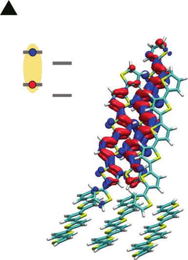
ARTICLE NATURE COMMUNICATIONS | https://doi.org/10.1038/s41467-020-18439-z
a 0.8 b c
Standing 7 Standing 105 Standing
1.5×10
Lying Lying Lying
Photon counts (a.u.)
Photon counts (a.u.)
4
10
Absorbance (a.u.)
0.6 Mixed Mixed Mixed
7 Prompt
1.0×10 103
0.4
102
0.2 5.0×10⁶
101
0.0 0.0 100
350 400 450 500 550 600 500 550 600 650 700 0 1 2 3 4 5
Wavelength (nm) Wavelength (nm) Time (ns)
d e f
2.0 2.0 2.0
1.5 1.5 1.5
Qz/(Å–1)
Qz/(Å–1)
Qz/(Å–1)
1.0 1.0 1.0
0.5 0.5 0.5
0.0 0.0 0.0
0.0 0.5 1.0 1.5 2.0 0.0 0.5 1.0 1.5 2.0 0.0 0.5 1.0 1.5 2.0
Qxy /(Å–1) Qxy /(Å–1) Qxy /(Å–1)
g Standing h Mixed i Lying
Fig. 3 Morphological and spectroscopic characterisation for the orientation of α-6T thin films. a Absorbance spectra for α-6T thin films with different
molecular orientations where the lying molecules show the highest absorbance and the mixed orientation film lies in between the lying and standing
samples. b Photoluminescence (PL) spectra normalised with the absorbance at the excitation wavelength of 450 nm for α-6T thin films with different
molecular orientations where the PL quenching is observed in the mixed molecules. c Time-correlated single photon counting for α-6T thin films with
different molecular orientations (standing, mixed and lying) revealing a faster PL decay in the presence of both standing and lying orientations. The grey
dots indicate the prompt decay (instrument response function), which in the case of the mixed and lying orientations induces an artefact at 1.3 ns. d–f
Grazing-incidence wide-angle X-ray scattering (GIWAXS) diffraction images showing that the molecular orientation of α-6T thin films can be tuned with
specific processing conditions. The peaks indicated by red and blue circles originate from crystallites with standing and lying molecules, respectively. g–i,
schematic morphology for α-6T thin films with different molecular orientations (standing, mixed, and lying).
at the early time suggests that the initially generated α-6T Turning to the α-6T-based HOSC with rubrene as BL, similar
excitons exhibit at least partial CT state character, as discussed exciton decay lifetimes were observed (Supplementary Figs. 7 and
further below. The decay of this EA feature on the timescale of 8). Except for a slightly faster charge recombination, all the
free carrier generation is most likely associated with field spectral features are nearly identical with those in pristine α-6T
screening as charges localise in separate domains, discussed thin films on ITO, indicating that efficient free charge carrier
further below25. We further carried out TA measurements for generation is not only present in devices but also in α-6T thin
pump fluences from 5–20 μJ cm−2 (Supplementary Fig. 6a). The films. This confirms our conclusions above that device interfaces
kinetics at 780 nm exhibit a strong dependence on the pump are not the origin of charge generation and indicates rather that
fluence, with decay dynamics accelerating at higher fluences this is a bulk phenomenon inherent to α-6T, one that is not
characteristic of bimolecular recombination. Fitting the kinetics usually observed in pristine organic materials.
gives a bimolecular rate constant on the order of 10−11 cm3 s−1 Efficient free charge generation in pristine organic semicon-
(Supplementary Fig. 6b), which is of similar magnitude or slower ductors without intermolecular CT character has been rarely
than that observed in typical bulk heterojunction OSCs31–33. This reported to date (unless very high photon energies are used37)
fluence dependence therefore suggests that this PIA at 780 nm due to the strong binding energy of excitons in such materials
originates from free charge carriers rather than being caused by (typically estimated as several hundreds of meV). Only a few
the formation of CT or triplet states30,34–36. At low pump spectroscopic studies have suggested ultrafast photogeneration of
fluences, a negligible decay of this feature is observed for time free charge carriers in pristine organic small molecule films, with
delays up to 6 ns (plateau in Fig. 2b), indicative of long-lived free these reporting only low EQEs of less than 10% and more often
charge carrier generation. less than 1%37–40. For example, Keiderling et al. reported charge
4 NATURE COMMUNICATIONS | (2020)11:4617 | https://doi.org/10.1038/s41467-020-18439-z | www.nature.com/naturecommunications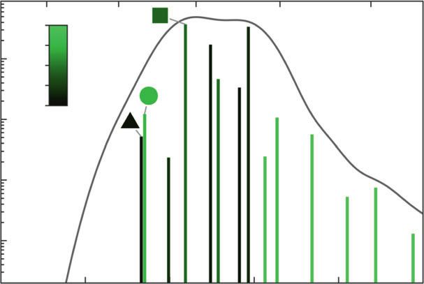
NATURE COMMUNICATIONS | https://doi.org/10.1038/s41467-020-18439-z                                                                   ARTICLE

generation in pristine PCBM thin films. This however results in                  the unit cell have an out-of-plane contribution, with the (3 1–1)
rather low efficiency photocurrent generation in PCBM HOSCs,                     plane being roughly parallel to the substrate. The diffraction
as reported by Burkhard et al.41,42. Other organic materials                    image for mixed films deposited at room temperature with a high
reported to exhibit charge or photocurrent generation include                   evaporation rate, shown in Fig. 3e, is a superposition of the
MEH-PPV, C60 and ZnPc38,43,44. However, in those reports either                 diffraction images of the films with lying and standing
the device performance was poor or the mechanisms for the fairly                orientation, shown in Fig. 3d and f, respectively. This is clearly
limited intrinsic charge generation have remained unexplained.                  visible by the existence of the lamellar peaks in the out-of-plane
In the next sections, we carry out further measurements to                      direction (red circles, standing orientation) and the in-plane
understand what underlines the efficient charge photogeneration                  direction (blue circles, lying orientation). In addition, to the
in pristine α-6T films.                                                          Bragg-rods visible in-plane (qxy = 1.31, 1.60 and 1.91 Å−1), which
                                                                                originate from the standing orientation, peaks can be seen at
                                                                                positions corresponding to lying orientations, further showing
Effect of orientation on energetics. It is known that charge                    that both molecular orientations are present in these films.
carrier energetics in organic semiconductor devices is strongly                 Analysis of the width of the GIWAXS peaks (Supplementary
intertwined with the molecular organisation in the solid state19.               Fig. 11) provides a lower limit of the average size of standing and
For instance, Duhm et al. have reported a 0.4 eV difference in the              lying crystallites, which for the mixed film are roughly 10 nm, i.e.,
ionisation potential of α-6T films as the orientation transitions                they are comparable with the exciton diffusion length of α-6T52.
from standing to lying18,45. Indeed, the presence of a possible                    We then carried out energy level measurements for thin films
energy offset between domains characterised by different mole-                  of standing or lying orientation on ITO using ambient
cular orientations may determine the favourable conditions for                  photoemission spectroscopy (APS), as shown in Fig. 4a. A
the charge separation. It is therefore essential to unravel the                 highest occupied molecular orbital (HOMO) level of 4.8 eV was
relationship between electronic properties, molecular organisa-                 observed for the standing film, compared to a value of 5.2 eV for
tion as well as the device processing conditions that confer the                the lying film. The APS measurements confirm the existence of an
possibility to control the first two aspects, as we address below.               energy offset δ ~ 0.4 eV between the HOMO levels of samples of
   A fast deposition of α-6T (1 Å/s) on unheated substrate, as                  lying and standing α-6T molecules.
employed for the films and HOSCs reported in Figs. 1 and 2                          APS measurements determine the energetics of charge carriers
above, results in a mixture of different orientations (standing and             at the surface of the two films of either standing or lying
lying) with respect to the ITO substrate46. In addition, we also                molecules. However, the energy landscape at the boundary
prepared films with mainly standing molecules, as well as films                   between two domains may well be affected by the different nature
containing mainly lying molecules, by employing fabrication                     of the environment (bulk-like, without interface to air). To
parameters which have been used in previous reports (see also                   complement APS measurements, we performed embedded many-
‘Methods’)46–48. In the lying orientation, the absorbance is                    body GW calculations, which was recently proved able to reach
maximised due to the parallel alignment between the transition                  quantitative accuracy in the determination of energy levels in
dipole moment of the molecule and the electric field vector of                   molecular solids53. We have explicitly considered a model
incident light (Fig. 3a)49,50. Since the amount of lying molecules is           interface between lying and standing molecules, obtaining an
lower in the mixed and standing films, the absorbance decreases                  inter-domain energy offset (δ ~ 0.4 eV) that is in close agreement
accordingly (Fig. 3a). The mixed orientation lies in between the                with the one determined by APS for the two films with different
two, indicating the co-existence of both orientations (see                      molecular orientations. Our calculations showed that this energy
GIWAXS data in Fig. 3d–f, discussed in detail below). While                     offset is determined by the different orientations of the molecular
the absorption spectra vary in shape and intensity for differently              quadrupoles in each side of the grain boundary, which dictate a
oriented films, the PL spectra retain the same shape since they                  step in the electrostatic potential across the interface (Fig. 4b, c)
originate from the lowest excited state after the excitations                   that affects occupied and unoccupied levels54. As sketched in
undergoing a significant vibrational relaxation. However, PL and                 Fig. 4d, standing and lying α-6T molecules behave therefore as
time-correlated single photon counting (TCSPC) show a                           the electron donating and the accepting components of a
quenching and a faster PL decay in the mixed film in comparison                  conventional organic heterojunction, consistent with the efficient
with the other two orientations (Fig. 3b, c), implying that an                  charge generation observed in our TA data above. In a working
enhanced exciton quenching mechanism is present in the mixed                    device, hole and electron transport to electrodes would then take
film containing both standing and lying α-6T phases.                             place in the standing and lying domains, respectively, exploiting
   Grazing-incidence wide-angle X-ray scattering (GIWAXS) was                   the intrinsic ambipolar character of α-6T films55,56 and consistent
employed to investigate the morphology of the films with                         with the reasonably slow bimolecular recombination observed for
standing, mixed and lying molecular orientations, as shown in                   this system.
Fig. 3d–f. For the films prepared at high temperatures (Fig. 3d),                   The presence of a 0.4 eV energy offset between standing and
the lamellar stacking peaks are clearly visible in the out-of-plane             lying domains may result in the occurrence of CT transitions,
direction, corresponding to standing molecules. In addition, the                where an electron is transferred from the standing to the lying
(H 1 1), (H 2 0) and (H 2 1) Bragg rods visible at 1.31, 1.60, and              domain, in the lowest-energy tail of the absorption spectrum.
1.91 Å−1 are typical for the herringbone motif adapted by the α-                These states could act as a gateway for efficient charge separation,
6T in the low temperature polymorph. The positions of the red                   as in conventional organic heterojunctions. To gain insight into
circles were derived from the unit cell reported for the low-                   low-energy optical excitations, we performed state-of-the-art
temperature polymorph by Horowitz et al.51. The same naming                     embedded Bethe–Salpeter equation calculations, which allowed us
for the unit cell parameters was used herein. In Fig. 3f, α-6T                  to accurately describe both Frenkel and CT excitations in large
deposited on top of an ITO substrate with a thin film of copper                  molecular systems57. The calculated absorption spectrum in Fig. 5
iodide (CuI, 2 nm) are shown. Compared to Fig. 3d, the lamellar                 reveals the complexity of the excited-state manifold, which is
peaks shifted to the in-plane direction, corresponding to lying                 heavily affected by delocalisation and hybridisation between
molecules. The rest of the peaks indicate that the unit cell lies               molecular (Frenkel, with high oscillator strength) and CT
down in two ways. One in which the b-axis of the unit cell is                   excitons. The brightest exciton is computed at 2.42 eV (hybrid
perpendicular to the surface and one in which both short axes of                Frenkel-CT, see Fig. 5c), in excellent agreement with the

NATURE COMMUNICATIONS | (2020)11:4617 | https://doi.org/10.1038/s41467-020-18439-z | www.nature.com/naturecommunications                           5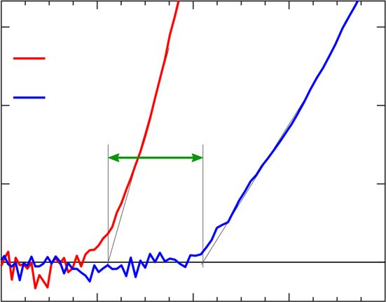
ARTICLE NATURE COMMUNICATIONS | https://doi.org/10.1038/s41467-020-18439-z
a c
0.2
Photocurrent1/3 (arb. units)
9
0
Standing /e
Lying –0.2
6
Potential (V)
3
0
0.2
4.4 4.8 5.2 5.6 6
Energy (eV) 0
b
–1 –0.2
LUMOs
–2 d -6T -6T
Energy (eV)
–3 standing lying
–4 LUMOs
–5 HOMOs
–6 HOMOs
Gas +induction +electrostatics
Fig. 4 Charge transport energy levels in α-6T thin films. a Ambient photoemission spectroscopy (APS) results for α-6T thin films with standing and lying
orientations presenting an energy difference δ ~ 0.4 eV between their HOMO levels (referenced to the vacuum level). b Evolution of HOMO and LUMO
levels calculated from embedded GW calculations for an interface between two domains with standing and lying α-6T molecules. Results are presented by
progressively adding induction (dielectric response) and electrostatic intermolecular interactions to gas-phase levels. This shows that the offset δ between
standing and lying molecules is entirely sourced by electrostatics. c Maps of the electrostatic potential illustrating the step-like variation across the
standing-lying interface. d Sketch of the energy levels of standing and lying α-6T molecules, playing the role of electron donor and acceptor component,
respectively.
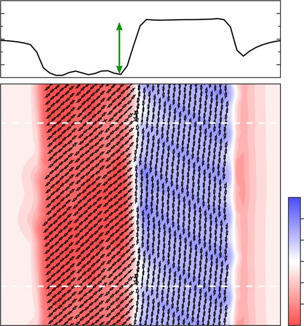
a Wavelength (nm) b c d
Frenkel exciton Standing-lying CT exciton Hybrid CT-Frenkel exciton
550 530 510 490 470
Energy: 2.37 eV Energy: 2.37 eV Energy: 2.42 eV
1.0 e–
Weight CT
100 0.5
Oscillator strength
h+
0.0
10 –1
-6T -6T +
standing lying
10–2
10–3
2.2 2.3 2.4 2.5 2.6 2.7
Energy (eV)
Fig. 5 Optical excitations from embedded Bethe–Salpeter calculations. a Absorption spectrum of the standing–lying α-6T interface. Bar colours quantify
the weight of inter-layer CT states of each excitation, showing that the lowest-energy region of the spectrum presents states that have a pronounced
charge separation, with hole and electron localised in the standing and lying domains, respectively. The energy of these states with spatially separated
charges is determined by the interfacial energy offset and can act as a gateway for an efficient charge splitting. b–d Electron–hole density plots and the
corresponding simplified energy-level sketches of representative low-energy excitations.
experimental absorption spectrum (Fig. 3g). Our calculations Discussions
further reveal that one of the two nearly degenerate lowest-energy Our combined experimental and theoretical analysis draws a
excitations, placed just ~50 meV below the brightest exciton, is an close analogy between the homojunction between crystalline
inter-domain CT state with the electron in the lying domain and domains with standing–lying orientations and D–A heterojunc-
the hole in the standing domain of the interface (see Fig. 5b). It is tions in conventional OSCs, even though in our single component
likely that thermal molecular motion, not included in our system the interfacial energy offset is solely determined by
modelling, may reshuffle the nature of these lowest-energy intermolecular electrostatic interactions, and not by any chemical
excitations, leading to a dynamic interconversion between Frenkel difference between the two species as in heterojunctions. Such an
and CT states, the latter providing the initial step for an efficient energy offset of electrostatic origin between the standing and
charge separation. lying orientations determines high-lying CT states that are nearly
6 NATURE COMMUNICATIONS | (2020)11:4617 | https://doi.org/10.1038/s41467-020-18439-z | www.nature.com/naturecommunications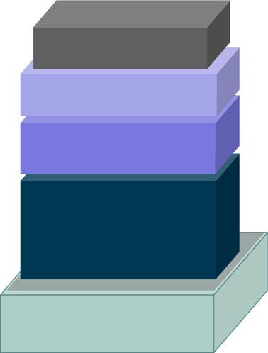
NATURE COMMUNICATIONS | https://doi.org/10.1038/s41467-020-18439-z                                                                                           ARTICLE

degenerate with bright excitons and that are, therefore, hardly                            Every investigated device was bottom illuminated, employing ITO as the anode and
resolved experimentally. Indeed, no extra low-energy CT                                    a 100-nm-thick Ag as the cathode. The full device structure of the investigated
                                                                                           devices is as follows: ITO/α-6T(70 nm)/BL(10 nm)/BPhen(8 nm)/Ag(100 nm),
absorption band is observed in the sensitively measured EQE                                where as ‘BL’ are denoted the materials used as buffer layers (Rubrene, C545T,
spectra (Supplementary Fig. 2). Furthermore, this agrees with our                          DBzA, TCTA, TPBA, TBPe, TPBI). The area of the devices was 6.44 mm2, defined
TA data for the α-6T film (Fig. 2) where an indication for the fast                         as the overlap between anode and the Ag cathode. All the used materials were
formation of exciton-CT hybrid states is found in the charge-                              purified twice in-house by vacuum gradient sublimation. The solar cells were
induced EA signal at 525 nm and is crucial towards charge gen-                             encapsulated in nitrogen atmosphere with a transparent encapsulation glass, fixed
                                                                                           by UV-hardened epoxy glue. Device characteristics from multiple batches are
eration. This type of high-lying hybrid exciton/CT states have                             provided in Supplementary Table 7.
also recently been proposed to be responsible for the low voltage
losses in the state-of-the-art D–A OSCs58. It has also recently                            Solar cells characterisation. Current voltage (J–V) measurements: J–V measure-
been suggested that CT separation may be assisted by the elec-                             ments were carried out on encapsulated devices in ambient conditions using a
trostatic interfacial fields in low energy offset, high performing                          source measurement unit (SMU 2400 Keithley, USA) and a simulated AM1.5G
OSCs based on a conventional D–A heterojunction59. The                                     illumination (16S-003-300-AM1.5G sunlight simulator, Solar Light Co., USA).
population of the inter-domain CT excitations following light                              Masks were used to minimise edge effects and to define an exact photoactive area
                                                                                           (2.78 mm2). A silicon (Si) photodiode (Hamamatsu S1337), calibrated by Fraun-
absorption appears to be the key for the unprecedented charge                              hofer ISE, was used as reference. Spectral mismatch was taken into account during
generation efficiency not only for a single component molecular                             the measurement.
film and devices, but also for D–A heterojunction OSCs.                                         EQE measurements: EQE measurements were performed using a xenon lamp
   We have investigated the origin of the remarkably high device                           (Oriel Xe Arch-lamp Apex, Newport, USA), a monochromator (Cornerstone 260
                                                                                           1/4 m, Newport, USA), an optical chopper and a lock-in amplifier (SR 7265, Signal
performance in α-6T-based HOSCs from various aspects                                       Recovery, USA). The EQE of the OSCs was measured with an aperture mask (2.78
including TA and APS as well as simulations. Using a single                                mm2) and without bias light. A Si photodiode (Hamamatsu S1337), calibrated at
material presents the advantage of achieving high voltage and                              Fraunhofer ISE, was used as reference.
allows great potential for controlled and reproducible morphol-                                Sensitive EQE (sEQE) measurements: The light of a quartz halogen lamp (50 W)
                                                                                           was chopped at 140 Hz and coupled into a monochromator (Newport Cornerstone
ogy and performance. We report a record high EQE of up to 40%                              260 1/4m, USA). The resulting monochromatic light was focused onto the OSC, its
and a VOC of 1.61 V for an HOSC employing only the donor                                   current at short-circuit conditions was fed to a current pre-amplifier before it was
organic molecule α-6T composed of identical crystallites with a                            analysed with a lock-in amplifier (Signal Recovery 7280 DSP, USA). The time
distribution of relative orientations.                                                     constant of the lock-in amplifier was set as 500 ms and the amplification of the pre-
                                                                                           amplifier was increased to resolve low photocurrents. The sEQE was determined by
   We have found that charge separation is driven by the elec-                             dividing the photocurrent of the OSC by the flux of incoming photons, which is
trostatic landscape generated at the interface between lying and                           obtained with calibrated Si and indium–gallium–arsenide photodiodes.
standing α-6T molecules, which creates an energy offset of about
0.4 eV between these two domains. We attribute this to be the                              Spectroscopy characterisation. UV–Vis absorption spectroscopy: A PerkinElmer
reason behind charge separation in pristine α-6T films: the                                 Lambda 25 spectrometer was used to carry out UV–Vis absorbance for thin film
standing domain plays the role of the donor and the lying domain                           samples.
is the acceptor. A generalisation of this result is that the ordered                           Steady state PL spectroscopy: Steady-state PL spectra were measured on a
                                                                                           Fluorolog-3 spectrofluorometer (FL 3–22, Horiba Jobin Yvon). All the samples
morphology and the contact between different crystal facets are                            were excited at 450 nm with a slit width of 5 nm. The emitted photons were
crucial to dissociate excitons, and that grain boundaries in single                        collected with the front-face geometry with a slit width of 5 nm.
component polycrystalline systems could be exploited as ‘het-                                  Time-correlated single photon counting (TCSPC): The DeltaFlex TCSPC system
erojunctions’. Engineering morphology in the preferred way is the                          (Horiba Scientific) was used to measure the time-resolved PL kinetics of thin film
key to generate energy offsets in single materials and facilitate                          samples. Samples were excited by a nano-LED at 404 nm. Photons were detected at
                                                                                           580 nm with a picosecond photon detector. The instrument temporal resolution is
charge generation pathway.                                                                 within 200 ps.
   This work reshapes the common understanding in the role of                                  TA spectroscopy measurements (TAS): A broadband femtosecond TA
‘donor’ and ‘acceptor’ in OSCs where this character is not only                            spectrometer Helios (Spectra Physics, Newport Corp.) was used to measure TAS
fixed by the primary chemical structure of the molecules but can                            for thin films and devices. Laser pulses (800 nm, 100 fs pulse duration) were
                                                                                           generated using a 1 kHz Ti:sapphire regenerative amplifier (Solstice, Spectra
also be modulated by interfacial packing and electrostatics. This                          Physics). One portion of the 800-nm pulses was directed to an optical parametric
further widens the broad potentiality in donor and acceptor                                amplifier (TOPAS) to generate the visible pump pulses at 450 nm. The rest of the
materials in OSCs.                                                                         800 nm pulses was routed onto a mechanical delay stage (6 ns time window) and
                                                                                           was directed through a sapphire crystal to generate a white light probe ranging
                                                                                           from 400–900 nm in the visible to near-infra-red region. The pump and probe
Methods                                                                                    beams were focused onto the same spot on the samples. During the measurements,
Thin films and devices fabrication. Thin film samples fabrication: The thin film              the thin film samples were kept in a quartz cuvette under continuous nitrogen flow
samples were prepared on glass substrates with a sputtered ITO layer. Thin films of         and the device samples were encapsulated.
either 20 or 60 nm were fabricated for each orientation. Both thicknesses were used            EA measurements: EA was measured on a full OPV device in the TAS set up
for the APS measurements, while GIWAXS and TAS were performed on samples,                  with a reflectance geometry. During the measurement, a square wave bias (5 V, 500
which had a thickness of 60 nm. Herein, three different processing methods were            Hz, 100 µs high-period) synced with the pulsed laser was applied to the device
used, leading to three different morphologies. When α-6T was deposited at low              using a digital delay generator (Stanford Research Systems DG645). The difference
evaporation rates (~0.1 Å/s) on substrates heated at 100 °C, the α-6T molecules            in reflectance between bias on and off was measured with various bias voltages,
orientate with their long axis almost perpendicular to the substrate, adopting an          yielding the EA spectrum under different electric fields.
upright ‘standing’ orientation. If a thin (2 nm) layer of CuI was used as templating           Ambient photoemission spectroscopy (APS) and surface photovoltage (SPV)
layer on top of the ITO electrode, the α-6T molecules deposited on CuI tend to             measurements: APS04 (KP Technology) system was employed to carry out the APS
orientate in parallel to the substrate, leading to a ‘lying’ orientation. This is due to   and SPV measurements. The measurement sequence is Kelvin probe, SPV, and
the stronger interaction between the π-conjugated system of α-6T and the d                 then APS. The Fermi level measurement uses the off-null Kelvin probe technique
orbitals of CuI, which lead to the templating effect48. Finally, depositing α-6T at        where the 2 mm gold tip is applied with oscillating positive or negative 7 V. The
room temperature and high evaporation rate (~1 Å/s) resulted in ‘mixed’ films               contact potential difference measured between the tip to the sample determines the
where the edge-on and face-on crystal phases are coexistent.                               dark work function of the sample. For SPV measurements, samples are kept in dark
    Device fabrication: The solar cells shown in this publication were processed by        for at least 10 min to reach equilibrium condition monitored by Kelvin probe. The
thermal evaporation in a custom-made vacuum system (Kurt J. Lesker, USA) with              white light source from quartz tungsten halogen lamps are switched on for 100 s
a base pressure of 10−7 mbar. During a processing run, different masks and                 after the first 20 s dark condition. The decay is also recorded for another 150 s after
movable shutters enable the variation of the device stacks or processing parameters,       illumination. To measure the HOMO levels, a UV light (−4.4 to −6.2 eV)
offering the possibility to produce and compare various devices at the same                illuminated the samples to generate photoemission of electrons. The photoemitted
processing conditions. Each device was fabricated onto either clean glass substrates       electrons interact with air molecules and generate radicals, which are further
or substrates with pre-structured ITO (Thin Film Devices, USA), which underwent            collected by the positively biased tip. The HOMO levels were subtracted linearly
an ozone treatment for cleaning before being transferred into the vacuum chamber.          from the cube root photoemission intensity to the baseline.

NATURE COMMUNICATIONS | (2020)11:4617 | https://doi.org/10.1038/s41467-020-18439-z | www.nature.com/naturecommunications                                                       7
ARTICLE NATURE COMMUNICATIONS | https://doi.org/10.1038/s41467-020-18439-z
Morphology characterisation. Grazing-incidence wide-angle X-ray scattering 18. Duhm, S. et al. Orientation-dependent ionization energies and interface
(GIWAXS): GIWAXS measurements were performed at the XRD1 beamline at the dipoles in ordered molecular assemblies. Nat. Mater. 7, 326–332 (2008).
ELETTRA synchrotron in Trieste. The thin films were illuminated under a grazing 19. D’Avino, G. et al. Electrostatic phenomena in organic semiconductors:
angle of 0.13° and the diffraction pattern was recorded with PILATUS 2M area fundamentals and implications for photovoltaics. J. Phys. Condens. Matter 28,
detector, which was placed 35 cm behind the samples. The measurements were 433002 (2016).
performed at a beam energy of 12.4 keV. The data were analysed with the WxDiff 20. Yin, Z., Wei, J. & Zheng, Q. Interfacial materials for organic solar cells: recent
software (c S.C.B.M.). advances and perspectives. Adv. Sci. 3, 1500362 (2016).
21. Xu, Z., Tang, B. Z., Wang, Y. & Ma, D. Recent advances in high performance
Simulations. Theoretical calculations were performed for a 2D-infinite interface blue organic light-emitting diodes based on fluorescence emitters. J. Mater.
between standing and lying a-6T domains. The interface morphology has been Chem. C. 8, 2614–2642 (2020).
built from the experimental crystal structure60 and relaxed with classical simula- 22. Burlingame, Q. et al. Reliability of small molecule organic photovoltaics with
tions (Supplementary Fig. 12) based on a validated force field61 performed with the electron-filtering compound buffer layers. Adv. Energy Mater. 6, 1601094
NAMD code62. Hybrid quantum/classical (QM/MM) GW53 and Bethe–Salpeter57 (2016).
many-body electronic structure calculations were performed with the FIESTA 23. Lanzani, G. et al. Ultrafast spectroscopy of photoexcitations in α-sexithienyl
package. These calculations considered up to six molecules in the QM region, films: evidence for excitons and polaron-pairs. Synth. Met. 84, 517–520
embedded into the MM electrostatic and polarisable crystalline environment (1997).
described with the charge response model in the MESCal code implementation63. 24. Taliani, C. & Blinov, L. M. The electronic structure of solid α-sexithiophene.
The starting Kohn–Sham orbitals were obtained with the gap-tuned density Adv. Mater. 8, 353–359 (1996).
functional ωB97X (ω = 0.141 Bohr−1) and the cc-pVTZ basis, which ensures 25. Causa’, M. et al. The fate of electron–hole pairs in polymer:fullerene blends for
accurate energy levels with single-iteration G0W0 calculations (Supplementary organic photovoltaics. Nat. Commun. 7, 12556 (2016).
Fig. 13 and Supplementary Table 4). Bethe–Salpeter calculations were performed 26. Devižis, A. et al. Dissociation of charge transfer states and carrier separation in
beyond the Tamm–Dancoff approximation, including all electron–hole transitions bilayer organic solar cells: a time-resolved electroabsorption spectroscopy
up to 10 eV (Supplementary Tables 5 and 6). Full details on electronic structure study. J. Am. Chem. Soc. 137, 8192–8198 (2015).
calculations are provided given in Supplementary Tables 3–6 and Supplementary 27. Watanabe, K. et al. Ultrafast decay dynamics of excited and charged states in
Figs. 13–19. alpha- sexithienyl film as revealed by femtosecond transient absorption and
picosecond fluorescence spectroscopy. J. Phys. Chem. B 101, 1510–1519
Reporting summary. Further information on research design is available in the Nature (1997).
Research Reporting Summary linked to this article. 28. Klein, G. Transient femtosecond spectroscopy in a-sexithiophene single
crystals. Chem. Phys. Lett. 320, 65–69 (2000).
29. Glowe, J.-F. et al. Charge-transfer excitons in strongly coupled organic
Data availability semiconductors. Phys. Rev. B 81, 041201 (2010).
The datasets generated during and/or analysed during the current study are available 30. Fichou, D., Horowitz, G., Xu, B. & Garnier, F. Stoichiometric control of the
from the corresponding author on reasonable request. successive generation of the radical cation and dication of extended α-
conjugated oligothiophenes: a quantitative model for doped polythiophene.
Received: 10 May 2020; Accepted: 21 August 2020; Synth. Met. 39, 243–259 (1990).
31. Wu, J. et al. Exceptionally low charge trapping enables highly efficient organic
bulk heterojunction solar cells. Energy Environ. Sci. 6, 11–13 (2020).
32. Gasparini, N. et al. Polymer: nonfullerene bulk heterojunction solar cells
with exceptionally low recombination rates. Adv. Energy Mater. 7, 1701561
References (2017).
1. Reucroft, P. J., Takahashi, K. & Ullal, H. Theoretical efficiency in an organic 33. Heiber, M. C. et al. Measuring the competition between bimolecular charge
photovoltaic energy conversion system. Appl. Phys. Lett. 25, 664–666 (1974). recombination and charge transport in organic solar cells under operating
2. Yu, G., Gao, J., Hummelen, J. C., Wudl, F. & Heeger, A. J. Polymer conditions. Energy Environ. Sci. 11, 3019–3032 (2018).
photovoltaic cells: enhanced efficiencies via a network of internal donor- 34. Lin, Y. L. et al. Enhanced sub-bandgap efficiency of a solid-state organic
acceptor heterojunctions. Science 270, 1789–1791 (1995). intermediate band solar cell using triplet–triplet annihilation. Energy Environ.
3. Vandewal, K. et al. Efficient charge generation by relaxed charge-transfer Sci. 10, 1465–1475 (2017).
states at organic interfaces. Nat. Mater. 13, 63–68 (2014). 35. Lanzani, G., Cerullo, G., Stagira, S., De Silvestri, S. & Garnier, F. Ultrafast
4. Kurpiers, J. et al. Probing the pathways of free charge generation in organic spectroscopy of dark states in solid state sexithiophene. J. Chem. Phys. 111,
bulk heterojunction solar cells. Nat. Commun. 9, 1–11 (2018). 6474–6480 (1999).
5. Liu, Q. et al. 18% Efficiency organic solar cells. Sci. Bull. 65, 272–275 (2020). 36. Lane, P. A. et al. Absorption spectroscopy of charged excitations in α-
6. Hou, J., Inganäs, O., Friend, R. H. & Gao, F. Organic solar cells based on non- sexithiophene: evidence for charge conjugation symmetry breaking. Chem.
fullerene acceptors. Nat. Mater. 17, 119–128 (2018). Phys. 210, 229–234 (1996).
7. Kwon, S. et al. Effect of processing additives on organic photovoltaics: recent 37. Köhler, A. et al. Charge separation in localized and delocalized electronic
progress and future prospects. Adv. Energy Mater. 7, 1601496 (2017). states in polymeric semiconductors. Nature 392, 903–906 (1998).
8. Kraner, S. et al. Dielectric function of a poly 38. Moses, D., Dogariu, A. & Heeger, A. J. Ultrafast detection of charged
(benzimidazobenzophenanthroline) ladder polymer. Phys. Rev. B 91, 195202 photocarriers in conjugated polymers. Phys. Rev. B - Condens. Matter Mater.
(2015). Phys. 61, 9373–9379 (2000).
9. Armin, A. et al. Engineering dielectric constants in organic semiconductors. J. 39. Hendry, E., Schins, J. M., Candeias, L. P., Siebbeles, L. D. A. & Bonn, M.
Mater. Chem. C. 5, 3736–3747 (2017). Efficiency of exciton and charge carrier photogeneration in a semiconducting
10. Vandewal, K., Benduhn, J. & Nikolis, V. C. How to determine optical gaps and polymer. Phys. Rev. Lett. 92, 1–4 (2004).
voltage losses in organic photovoltaic materials. Sustain. Energy Fuels 2, 40. Kozlov, O. V. et al. Ultrafast exciton-to-polaron conversion in densely packed
538–544 (2018). small organic semiconducting molecules. Adv. Opt. Mater. 5, 1700024 (2017).
11. Terao, Y., Sasabe, H. & Adachi, C. Correlation of hole mobility, exciton 41. Burkhard, G. F., Hoke, E. T., Beiley, Z. M. & Mcgehee, M. D. Free carrier
diffusion length, and solar cell characteristics in phthalocyanine/fullerene generation in fullerene acceptors and its effect on polymer photovoltaics. J.
organic solar cells. Appl. Phys. Lett. 90, 103515 (2007). Phys. Chem. C. 116, 26674–26678 (2012).
12. Menke, S. M., Luhman, W. A. & Holmes, R. J. Tailored exciton diffusion in 42. Keiderling, C., Dimitrov, S. & Durrant, J. R. Exciton and charge generation in
organic photovoltaic cells for enhanced power conversion efficiency. Nat. PC60BM thin films. J. Phys. Chem. C. 121, 14470–14475 (2017).
Mater. 12, 152–157 (2013). 43. Hahn, T. et al. Role of intrinsic photogeneration in single layer and bilayer
13. Roncali, J. & Grosu, I. The dawn of single material organic solar cells. Adv. Sci. solar cells with C60 and PCBM. J. Phys. Chem. C. 120, 25083–25091 (2016).
6, 1801026 (2019). 44. He, X. et al. Photogenerated intrinsic free carriers in small-molecule organic
14. Zhang, Y. et al. High-efficient charge generation in single-donor-component- semiconductors visualized by ultrafast spectroscopy. Sci. Rep. 5, 1–11 (2015).
based p-i-n structure organic solar cells. Sol. RRL 4, 1–9 (2020). 45. Li, Y., Li, P. & Lu, Z.-H. Molecular orientation and energy levels at organic
15. Tautz, R. et al. Structural correlations in the generation of polaron pairs in interfaces. Adv. Electron. Mater. 2, 1600306 (2016).
low-bandgap polymers for photovoltaics. Nat. Commun. 3, 970 (2012). 46. Lorch, C. et al. Templating effects of α-sexithiophene in donor–acceptor
16. Cnops, K. et al. 8.4% Efficient fullerene-free organic solar cells exploiting long- organic thin films. J. Phys. Chem. C. 119, 23211–23220 (2015).
range exciton energy transfer. Nat. Commun. 5, 1–6 (2014). 47. Hörmann, U. et al. Voc from a morphology point of view: the influence of
17. Crone, B. et al. Large-scale complementary integrated circuits based on molecular orientation on the open circuit voltage of organic planar
organic transistors. Nature 403, 521–523 (2000). heterojunction solar cells. J. Phys. Chem. C. 118, 26462–26470 (2014).
8 NATURE COMMUNICATIONS | (2020)11:4617 | https://doi.org/10.1038/s41467-020-18439-z | www.nature.com/naturecommunicationsNATURE COMMUNICATIONS | https://doi.org/10.1038/s41467-020-18439-z ARTICLE
48. Taima, T. et al. Sexithiophene-based photovoltaic cells with high light No. 722651 (SEPOMO). Computational resources were provided by the French GENCI-
absorption coefficient via crystalline polymorph control. J. Phys. Chem. C 121, TGCC infrastructure, by the Belgian Consortium des Équipements de Calcul Intensif
19699–19704 (2017). (CÉCI), funded by the Fonds de la Recherche Scientifiques de Belgique (F.R.S.-FNRS)
49. Nakano, K. & Tajima, K. Organic planar heterojunctions: from models for under Grant No. 2.5020.11, and by the Tier-1 supercomputer of the Fedération Wallo-
interfaces in bulk heterojunctions to high-performance solar cells. Adv. Mater. nie-Bruxelles, infrastructure funded by the Walloon Region under Grant Agreement No.
29, 1603269 (2017). 1117545. D.B. is a FNRS Research Director. We acknowledge Elettra Sincrotrone Trieste
50. Kouki, F., Spearman, P., Valat, P., Horowitz, G. & Garnier, F. Experimental for providing access to its synchrotron radiation facilities and we thank Luisa Barba for
determination of excitonic levels in α-oligothiophenes. J. Chem. Phys. 113, assistance in using beamline XRD1.
385–391 (2000).
51. Horowitz, G. et al. Growth and characterization of sexithiophene single
crystals. Chem. Mater. 7, 1337–1341 (1995).
Author contributions
Y.D., V.C.N., J.R.D., A.A.B. and K.V. designed the experiments. V.C.N. prepared films
52. Matsushima, T., Matsuo, H., Yamamoto, T., Nakao, A. & Murata, H.
and fabricated and optimised the photovoltaic devices. Y.D. performed the absorbance,
Horizontally oriented molecular thin films for application in organic solar
steady-state and time-resolved PL measurements and transient absorption studies and
cells. Sol. Energy Mater. Sol. Cells 123, 81–91 (2014).
their analysis. Y.D. and X.Z. carried out EA measurements. F.T. and S.C.B.M. performed
53. Li, J., D’Avino, G., Duchemin, I., Beljonne, D. & Blase, X. Accurate description
and analysed the GIWAXS measurements. J.K. and J.B. measured and analysed the
of charged excitations in molecular solids from embedded many-body
sensitive EQE spectra. V.C.N. performed the J–V and EQE measurements. Y.-C.C.
perturbation theory. Phys. Rev. B 97, 1–13 (2018).
performed the APS measurements. J.-S.K., D.S., S.C.B.M., J.R.D., A.A.B. and K.V.
54. Schwarze, M. et al. Impact of molecular quadrupole moments on the energy
supervised their team members involved in this project. J.R.D, A.A.B., J.-S.K. and K.V.
levels at organic heterojunctions. Nat. Commun. 10, 2466 (2019).
supervised the overall project. G.D., G.L., J.L., L.M., X.B. and D.B. designed and per-
55. Opitz, A. et al. Bipolar charge transport in organic field-effect transistors:
formed the theoretical and computational analysis. Y.D. and V.C.N. wrote the manu-
enabling high mobilities and transport of photo-generated charge carriers by a
script. All authors contributed to the critical analysis of the results and to the revision of
molecular passivation layer. Org. Electron. 13, 1614–1622 (2012).
the manuscript.
56. Sakanoue, T., Yahiro, M., Adachi, C., Takimiya, K. & Toshimitsu, A. Electrical
characteristics of single-component ambipolar organic field-effect transistors
and effects of air exposure on them. J. Appl. Phys. 103, 094509 (2008). Competing interests
57. Duchemin, I., Guido, C. A., Jacquemin, D. & Blase, X. The Bethe-Salpeter The authors declare no competing interests.
formalism with polarisable continuum embedding: reconciling linear-response
and state-specific features. Chem. Sci. 9, 4430–4443 (2018).
58. Liu, J. et al. Fast charge separation in a non-fullerene organic solar cell with a Additional information
small driving force. Nat. Energy 1, 16089 (2016). Supplementary information is available for this paper at https://doi.org/10.1038/s41467-
59. Perdigón-Toro, L. et al. Barrierless free charge generation in the high- 020-18439-z.
performance PM6:Y6 bulk heterojunction non-fullerene solar cell. Adv. Mater.
32, e1906763 (2020). Correspondence and requests for materials should be addressed to J.-S.K., G.D’A., J.R.D.
60. Siegrist, T. et al. The crystal structure of the high-temperature polymorph of or K.V.
α-hexathienyl (α-6T/HT). J. Mater. Res. 10, 2170–2173 (1995).
61. Pizzirusso, A., Savini, M., Muccioli, L. & Zannoni, C. An atomistic simulation Peer review information Nature Communications thanks Zhixiang Wei and the other,
of the liquid-crystalline phases of sexithiophene. J. Mater. Chem. 21, 125–133 anonymous, reviewer(s) for their contribution to the peer review of this work. Peer
(2011). reviewer reports are available.
62. Phillips, J. C. et al. Scalable molecular dynamics with NAMD. J. Comput.
Chem. 26, 1781–1802 (2005). Reprints and permission information is available at http://www.nature.com/reprints
63. D’Avino, G., Muccioli, L., Zannoni, C., Beljonne, D. & Soos, Z. G. Electronic
polarization in organic crystals: a comparative study of induced dipoles and Publisher’s note Springer Nature remains neutral with regard to jurisdictional claims in
intramolecular charge redistribution schemes. J. Chem. Theory Comput. 10, published maps and institutional affiliations.
4959–4971 (2014).
Open Access This article is licensed under a Creative Commons
Acknowledgements Attribution 4.0 International License, which permits use, sharing,
The authors thank Maxim Pschenitchnikov for useful discussion. This work was sup- adaptation, distribution and reproduction in any medium or format, as long as you give
ported by the German Federal Ministry of Education and Research (BMBF) through the appropriate credit to the original author(s) and the source, provide a link to the Creative
Innoprofile project ‘Organische p-i-n Bauelemente2.2’ (FKZ 03IPT602X), UKRI Global Commons license, and indicate if changes were made. The images or other third party
Challenge Research Fund project SUNRISE (EP/P032591/1). Y.-C.C. acknowledges the material in this article are included in the article’s Creative Commons license, unless
President’s PhD Scholarship funding by Imperial College London. A.A.B. is a Royal indicated otherwise in a credit line to the material. If material is not included in the
Society University Research Fellow. J.-S.K. and J.R.D. acknowledge the Global Research article’s Creative Commons license and your intended use is not permitted by statutory
Laboratory Program of the National Research Foundation (NRF) funded by the Ministry regulation or exceeds the permitted use, you will need to obtain permission directly from
of Science, ICT & Future Planning (NRF-2017K1A1A2 013153). This project has also the copyright holder. To view a copy of this license, visit http://creativecommons.org/
received funding from the European Research Council (ERC) under the European licenses/by/4.0/.
Union’s Horizon 2020 research and innovation programme (grant agreements 639750
and 864625). The work in Mons was supported by the European Union’s Horizon 2020
research and innovation programme under Marie Sklodowska Curie Grant agreement © The Author(s) 2020
NATURE COMMUNICATIONS | (2020)11:4617 | https://doi.org/10.1038/s41467-020-18439-z | www.nature.com/naturecommunications 9You can also read