Power Test of the First Two HL-LHC Insertion Quadrupole Magnets Built at CERN
←
→
Page content transcription
If your browser does not render page correctly, please read the page content below
IEEE TRANSACTIONS ON APPLIED SUPERCONDUCTIVITY, VOL. 32, NO. 6, SEPTEMBER 2022 4003305
Power Test of the First Two HL-LHC Insertion
Quadrupole Magnets Built at CERN
F. J. Mangiarotti , G. Willering , L. Fiscarelli , M. Bajko , L. Bottura, V. Desbiolles,
A. Devred , Senior Member, IEEE, J. Ferradas Troitino , S. Izquierdo Bermudez , R. Keijzer , F. Lackner ,
A. Milanese , G. Ninet, H. Prin, E. Ravaioli , S. Russenschuck , E. Takala , and E. Todesco
Abstract—The High-Luminosity project (HL-LHC) of the TABLE I
CERN Large Hadron Collider (LHC), requires low β* quadrupole MQXFBP1 AND MQXFBP2 MAIN PARAMETERS
magnets in Nb 3 Sn technology that will be installed on each side
of the ATLAS and CMS experiments. After a successful short-
model magnet manufacture and test campaign, the project has
advanced with the production, assembly, and test of full-size 7.15-
m-long magnets. In the last two years, two CERN-built prototypes
(MQXFBP1 and MQXFBP2) have been tested and magnetically
measured at the CERN SM18 test facility. These are the longest
accelerator magnets based on Nb 3 Sn technology built and tested
to date. In this paper, we present the test and analysis results
of these two magnets, with emphasis on quenches and training,
voltage-current measurements and the quench localization with
voltage taps and a new quench antenna.
Index Terms—Low beta quadrupole, Nb3 Sn, quench,
superconducting magnets. TABLE II
COILS USED IN MQXFBP1 AND MQXFBP2
I. INTRODUCTION
S PART of the HL-LHC project at CERN, the Nb-Ti inner
A triplet quadrupole magnets near the ATLAS and CMS
interaction points will be replaced with large aperture Nb 3 Sn
quadrupole magnets, named MQXF [1], [2]. These magnets are figures of these two prototype magnets are shown in Table I,
developed, manufactured, and tested in a collaboration between and the coils used in each magnet in Table II.
CERN and the US HL-LHC Accelerator Upgrade Project (AUP).
The MQXF program includes the construction and test of several II. TEST PLAN AND FEATURES
short-length model magnets, the 4.2-m-long magnets for Q1
A. Magnet Powering, Quench Detection and Protection
and Q3 (constructed by AUP [3]), and the 7.15-m-long magnets
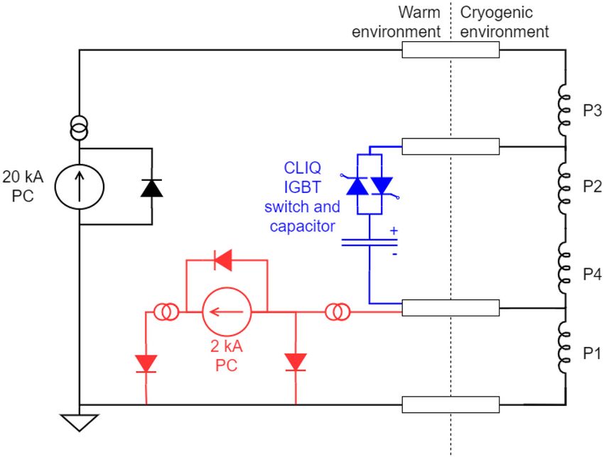
for Q2a and Q2b (MQXFB, constructed by CERN). The first MQXFBP1 and MQXFBP2 were tested in the A1 horizontal
two MQXFB full-length prototype magnets (MQXFBP1 and test bench at the SM18 magnet test facility at CERN [5]. The
MQXFBP2) were manufactured, assembled and cryostated at magnets were powered with a 1-quadrant, 20 kA DC power
CERN [4]. MQXFBP1 was tested in summer–fall 2020, and converter. In addition, during the MQXFBP2 test campaign,
MQXFBP2 was tested in winter–spring and fall 2021. Key an additional 1-quadrant, 2 kA DC power converter was used
for trimmed powering tests: the current in one of the coils was
reduced for diagnostic purposes. The circuit diagram is shown
Manuscript received November 26, 2021; revised February 13, 2022 and
February 21, 2022; accepted February 28, 2022. Date of publication March in Fig. 1.
8, 2022; date of current version March 25, 2022. (Corresponding author: F. J. The magnets were tested using the baseline quench detection
Mangiarotti.) and protection systems for operation in the LHC:
F. J. Mangiarotti, G. Willering, L. Fiscarelli, M. Bajko, L. Bottura, V. Des- r Quench detection with a universal quench detection system
biolles, A. Devred, J. Ferradas Troitino, S. Izquierdo Bermudez, F. Lackner,
A. Milanese, G. Ninet, H. Prin, E. Ravaioli, S. Russenschuck, E. Takala, (uQDS, see [6]), which allows to set variable voltage
and E. Todesco are with CERN, CH-1211 Geneva, Switzerland (e-mail: thresholds and validation windows depending on the mag-
franco.julio.mangiarotti@cern.ch).
net current.
R. Keijzer is with CERN, CH-1211 Geneva, Switzerland, and also
with Universiteit Twente, 7522 Enschede, The Netherlands (e-mail: r Magnet protection with outer-layer quench heaters [7],
ruben.keijzer@cern.ch). [8] and coupling-loss induced quench system (CLIQ [9]).
Color versions of one or more figures in this article are available at
https://doi.org/10.1109/TASC.2022.3157574. Energy extraction by means of a dump resistor was not
Digital Object Identifier 10.1109/TASC.2022.3157574 used for these magnets.
This work is licensed under a Creative Commons Attribution 4.0 License. For more information, see https://creativecommons.org/licenses/by/4.0/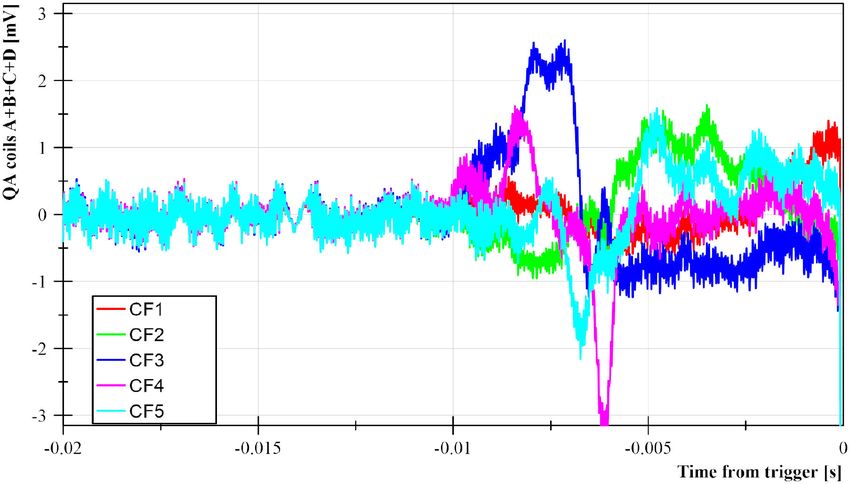
4003305 IEEE TRANSACTIONS ON APPLIED SUPERCONDUCTIVITY, VOL. 32, NO. 6, SEPTEMBER 2022
Fig. 3. Quench current vs. ramp rate at 1.9 and 4.5 K of MQXFBP1 and
MQXFBP2. Quenches in MQXFBP2 were all quench location 2.A; the location
of quenches in MQXFBP1 is noted next to each point.
Fig. 1. Circuit diagram for the test of MQXFB prototypes. PC indicates
the DC power converters. Black shows the standard powering circuit. Blue
corresponds to the CLIQ system. Red shows the additional powering circuit for
the trimmed powering of pole P1. The blue and red circuits were not connected
simultaneously.
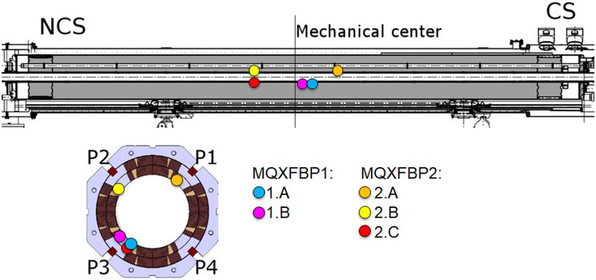
Fig. 4. Longitudinal location (top) and in the cross section (bottom left) of the
recurring quenches in the MQXFB prototypes, based on the voltage taps and
quench antenna measurements.
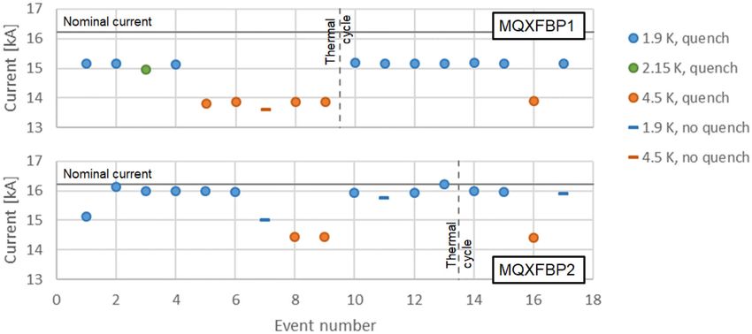
Fig. 2. Natural quench history at nominal test ramp rate of MQXFBP1 (top)
and MQXFBP2 (bottom).
B. Magnet Instrumentation reached its limit at the second ramp to quench, at 15.95 kA
(98.2% of nominal current). In each magnet, the quenches at
The four coils of both prototypes were instrumented with 8 the quench limit had the same signature, in terms of resistive
voltage taps in each of their two layers, for a total of 64 voltage voltage growth rate, coil segment that quenched, and quench
taps per magnet. Of these, only 8 (plus redundancy) are required antenna signals.
for LHC operation, one voltage tap at each extremity of each Further investigation of the quench performance was done at
coil. The remaining 56 voltage taps were installed to be used for different temperature levels (1.9, 2.15 and 4.5 K) and ramp rates
quench localization and performance analysis. (1, 20, 50, 100, 150 and 200 A/s). The quenches at 100 A/s and
In addition, the magnets were instrumented with strain gauges below were in the inner-layer pole turn straight section, close to
on the rods and with optical fibers with Bragg gratting (FBG) the magnet mechanical center. In MQXFBP1, these quenches
sensors in the coil poles [10]; MQXFBP1 was also equipped were in pole P3, on the left of the pole at low ramp rate (location
with strain gauges on the magnet shell. The mechanical mea- 1.A) and on the right of the pole at higher ramp rate (1.B). In
surements will be reported in another publication. MQXFBP2, the quenches were on pole P1, always on the left
On the test bench, the magnets were equipped with an anti- of the pole (location 2.A). Quenches above 100 A/s were in the
cryostat, that allows the bore to be accessible at room tempera- inner-layer multi-turn blocks, near the magnet heads, and are
ture during magnet operation. This allowed us to use a dedicated attributed to heating due to high AC losses. A summary of the
array of induction coils that can be used for quench localization, quench current at 100 A/s and below is shown in Fig. 3. The
usually referred to as quench antenna, and a stretched wire or a quench locations are shown in Fig. 4.
rotating-coil magnetometer for magnetic field measurements. The resistive voltage development after quench was compared
to previous experience in MQXF short-model magnets. For both
III. TEST AND MEASUREMENT RESULTS magnets, the resistive voltage growth was similar or slower
than in the short models at similar current, see an example for
A. Quench Performance
MQXFBP2 in Fig. 5. The quench propagation velocity at 1.9 K
The natural quench history at nominal test ramp rate (20 A/s) in both magnets is around 60–70 m/s.
of the two magnets is shown in Fig. 2. Training was done at Longitudinal quench localization was done by shifting the
1.9 K. MQXFBP1 reached a quench limit during the first ramp to quench antenna along the magnet axis: coarse localization was
quench, at 15.17 kA (93.4% of the nominal current). MQXFBP2 done with nine 600-mm-sectors that cover most of the magnet.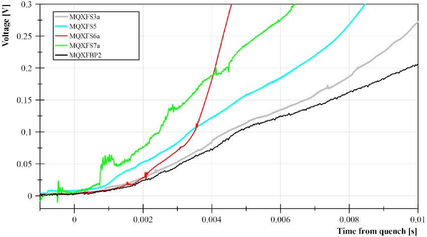
MANGIAROTTI et al.: POWER TEST OF THE FIRST TWO HL-LHC INSERTION QUADRUPOLE MAGNETS BUILT AT CERN                                                     4003305

Fig. 5. Resistive voltage development in the recurring quench location at
20 A/s, 1.9 K in MQXFBP2 (black) compared to quenches in the short models
at similar current. In all cases the quench location is similar (inner-layer pole
turn or adjacent turns).                                                            Fig. 7. Transfer function measurements in MQXFBP1 and MQXFBP2, per-
                                                                                    formed during a stairstep current cycle. The transfer function measured on
                                                                                    MQXFBP2 is +60 unit compared to MQXFBP1.

                                                                                                                TABLE III
                                                                                       FIELD QUALITY IN MQXFBP1 AND MQXFBP2, IN TERMS OF INTEGRAL
                                                                                    FIELD, AT 50 MM REFERENCE RADIUS. VALUES IN UNITS OF 10−4 . MAGNETIC
                                                                                      SHIMS WERE INSTALLED IN MQXFBP2 TO CORRECT THE B3 COMPONENT
                                                                                                   FOLLOWING THE MEASUREMENTS AT 300 K

Fig. 6. Example of quench antenna signals after a quench in MQXFBP2.
Signals CF1 through CF4 correspond to the 50 mm coils; CF5 corresponds to
the 100 mm coil. In this case, quench antenna segments CF3 and CF4 react to
the quench first, around time −10 ms, indicating that the quench starts in that
location.

Once a recurring quench location was identified, the localiza-
tion was narrowed-down by shifting the quench antenna 200–
300 mm along the axis. A last step of localization was done by                      the room temperature measurements, magnetic shims were in-
placing the quench antenna end (consisting of four 50 mm, one                       stalled in MQXFBP2 to correct b3. The correction resulted to
100 mm and one 300 mm induction coils) around the quench                            be effective at nominal level (b3 < 2 units). A summary of the
location. This last step allows to identify the quench location                     magnetic field quality at both temperatures in Table III
within ±50 mm. One example of quench antenna signal for the
last localization step is shown in Fig. 6.                                          C. V-I Measurements
                                                                                       V-I measurements (see [3], [12]) have been done in both
B. Magnetic Measurements                                                            MQXFB prototype magnets. During uniform stair-step current
   Magnetic field measurements were performed in both mag-                          cycles in MQXFBP1 decaying voltages were observed in the
nets at low current and room temperature with rotating-coil                         quenching locations and the segment between them (corre-
magnetometers, and at the highest stable current at 1.9 K with                      sponding to the inner layer pole turn head) upon reaching a
the stretched wire. In addition, for MQXFBP2 the magnetic field                     current plateau near the quench current. The voltage decay is
was measured with rotating-coil magnetometers at 1.9 K. The                         negative in quench location 1.A, and positive in the other two
transfer function measured on MQXFBP2 is +60 units in 10000                         segments. At that current level, the voltage decays to a level
with respect to MQXFBP1. This difference is not visible on                          above the previous current plateau, indicating the start of the
measurements at ambient temperature. About +20 units can be                         superconducting normal transition. This is shown in Fig. 8.
explained by the presence of magnetic shims. A summary of                              In MQXFBP2, during a similar uniform stair-step curreny
transfer function measurements at 1.9 K is given in Fig. 7.                         cycle, the decaying voltage in the quench location is much
   The field quality in both magnets is within specifications.                      smaller, and mainly a non-decaying voltage increase is observed.
A systematic b6 component of about −5 units is present on                           Further investigations were done with a current cycle with a
MQXFBP1. It has been later corrected by removing 0.125 mm                           higher density current step near the quench current, and the
from the midplane before impregnation. The effectiveness of                         start of the superconducting-normal transition could be better
the correction is visible on MQXFBP2. In addition, based on                         measured. In Fig. 9 the results in the quench location segment for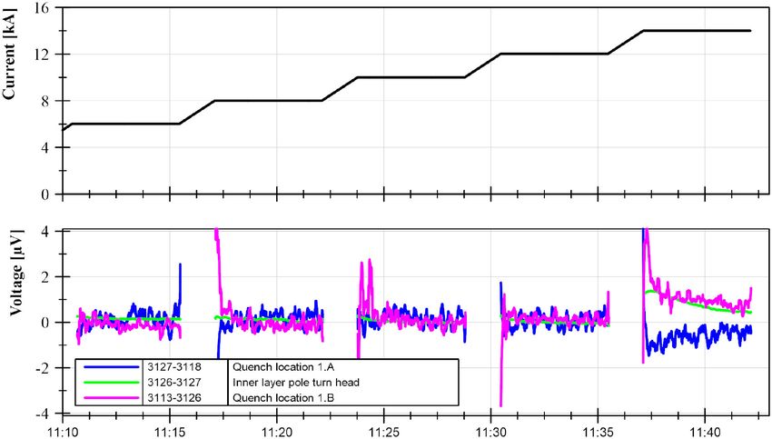
4003305 IEEE TRANSACTIONS ON APPLIED SUPERCONDUCTIVITY, VOL. 32, NO. 6, SEPTEMBER 2022
Fig. 10. Trimmed powering quench summary of MQXFBP2. Quenches in P2
are in quench location 2.B, and in P3 in quench location 2.C.
Fig. 8. V-I measurements in MQXFBP1, shown as current and voltage versus
time, during an uniform stair-step current cycle. During the last current plateau
a voltage offset and decay can be observed.
center. Their ramp rate and temperature dependency is mostly
“normal”. Both magnets show early superconducting-normal
transition observed in the quench location segments, with de-
caying voltages. The quench propagation velocity is similar to
other MQXF short magnets at similar quench current. All these
indicators point towards local damage of the superconductor, as
opposed to distributed (over several twist pitches) degradation
as was seen in early short models of the CERN 11 T Nb 3 Sn
dipole [15], [16].
The decaying voltages in the MQXFBP1 V-I measurements
during current flat-tops indicate current redistribution between
strands, likely caused by a non-uniform degradation component.
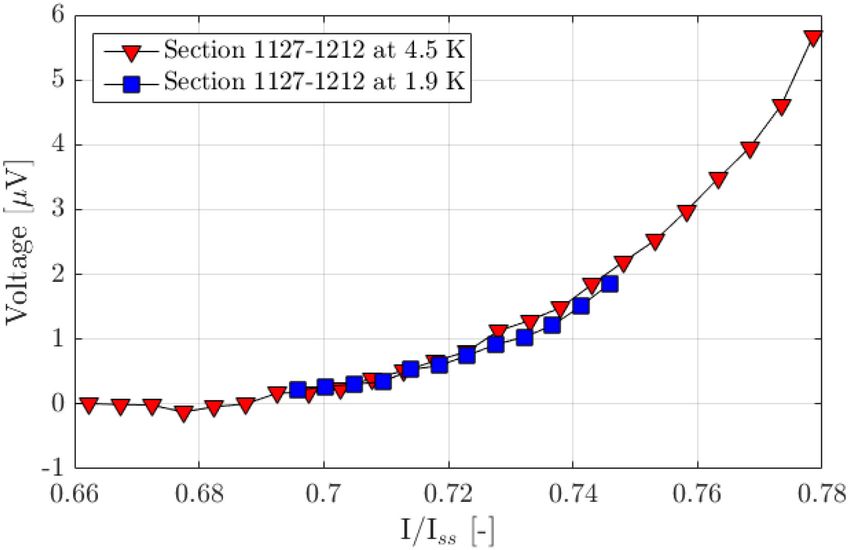
Fig. 9. V-I measurements the quench location segment in MQXFBP2, at 1.9 Also, negative decaying voltages cannot be explained by dam-
(blue) and 4.5 K (red), during a current cycle with high density of current plateaus
near the quench current. The current has been normalized to the short sample age in the segment measured. This topic is discussed in detail
limit at each temperature. Note that the magnetic field in the measured segment in [12]. For such type of degradation, the expected degradation
increases with the current. The quench happens at a lower fraction of short location would be the quench location at high ramp rate and
sample limit at 1.9 K. Error bars in the vertical axis are around 0.1 μV (not
shown). high temperature, in this case location 1.B. In MQXFBP2, the
expected degradation location is the quench location.
such tests is shown, at 1.9 and 4.5 K, with the current normalized
to the short sample limit indicated in Table I. The inner pole
turn segments of the other coils also show an early start of the V. CONCLUSION
transition, at up to 1/5 of the voltage level of the quench-location The first two MQXFB prototypes magnets have been power
segment. tested at the CERN SM18 test facility. MQXFBP1 reached
15.17 kA (93.4% of nominal current, corresponding to an op-
D. Trimmed Powering of MQXFBP2 eration energy of 6.5 TeV) and MQXFBP2 reached 15.95 kA
(98.2% of nominal current, corresponding to 6.9 TeV).
In preparation for the trimmed powering of MQXFBP2, the
The field quality of the two tested magnets resulted to be
powering setup, quench behavior and agreement with simula-
within specifications. A systematic b6, present on MQXFBP1
tions were tested on the short magnet MQXFS7b [13], [14], and
and already seen on the short models, has been successfully
the protection scheme without CLIQ was verified at increasing
corrected by shimming the coil midplane. On MQXFBP2, the
currents in MQXFBP2. The magnet was then ramped to quench
b3 component has been corrected by applying magnetic shims
at 1.9 and 4.5 K, using a trim current of 0, 2.5 and 5% of the main
in the bladder slots.
current. The results of trimmed powering is shown in Fig. 10.
The performance limitation in both MQXFB prototypes is
With a 5% trim, pole P3 quenches in location 2.C at 20 A/s (1.9
expected to be caused by local damage of the superconductor,
and 4.5 K), pole P2 quenches in location 2.B at 1 A/s, 4.5 K,
in the quench location at high ramp rate. This location was
and no quench is recorded up to 17 kA at 1 A/s, 1.9 K. All
identified within ±50 mm, to allow further investigation at room
quenches were in the inner layer pole turn straight segment of
temperature.
the respective coils.
Trimmed powering of the limiting coil in MQXFBP2 allowed
the other three coils to be powered above the performance limit.
IV. DISCUSSION
With a 5% trim, other two coils quenched at around 500–600 A
Both magnets have similar behavior: they have a quench cur- higher than the limiting coil at the same temperature and ramp
rent limit in the inner pole turn of one coil, near the mechanical rate conditions.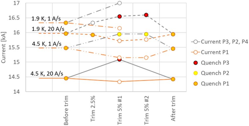
MANGIAROTTI et al.: POWER TEST OF THE FIRST TWO HL-LHC INSERTION QUADRUPOLE MAGNETS BUILT AT CERN                                                        4003305

                                  REFERENCES                                        [8] E. Ravaioli et al., “Quench protection performance measurements in the
                                                                                        first MQXF magnet models,” IEEE Trans. Appl. Supercond., vol. 28, no. 3,
 [1] E. Todesco et al., “A first baseline for the magnets in the high luminosity        Apr. 2018, Art. no. 4701606.
     LHC insertion regions,” IEEE Trans. Appl. Supercond., vol. 24, no. 3,          [9] E. Ravaioli, “CLIQ,” Ph.D. dissertation, Univ. Twente, 2015.
     Jun. 2014, Art. no. 4003305.                                                  [10] L. Bianchi, “Strain measurements on MQXFBP1 superconducting mag-
 [2] E. Todesco et al., “The high luminosity LHC interaction region mag-                net,” CERN, Tech. Rep. EDMS 1851752, 2021.
     nets towards series production,” Supercond. Sci. Technol., vol. 34, 2021,     [11] F. J. Mangiarotti et al., “Powering Performance and Endurance Beyond
     Art. no. 053001.                                                                   Design Limits of HL-LHC Low-Beta Quadrupole Model Magnets,” IEEE
 [3] G. Ambrosio et al., “Lessons Learned From the Prototypes of the MQXFA              Trans. Appl. Supercond., vol. 31, no. 5, Aug. 2021, Art. no. 4000805.
     Low-Beta Quadrupoles for HL-LHC and Status of Production in the US,”          [12] R. Keijzer et al., “Modelling V-I measurements of Nb3 Sn accelerator
     IEEE Trans. Appl. Supercond., vol. 31, no. 5, Aug. 2021, Art. no. 4001105.         magnets with conductor degradation,” IEEE Trans. Appl. Supercond., to
 [4] S. I. Bermudez et al., “Progress in the development of the Nb3 Sn MQXFB            be published, doi: 10.1109/TASC.2022.3153247.
     quadrupole for the HiLumi upgrade of the LHC,” IEEE Trans. Appl.              [13] F. Mangiarotti, “MQXFS7b trim test results,” CERN, Tech. Rep. EDMS
     Supercond., vol. 31, no. 5, Aug. 2021, Art. no. 4002007.                           2621655, 2021.
 [5] M. Bajko, “SM18 the CERN magnet test facility,” Accessed: Feb. 11, 2022.      [14] E. Ravaioli, “Analysis of the electrical and thermal behavior of coil 211
     [Online]. Available: https://indico.cern.ch/event/704235/contributions/            of the MQXFS7b magnet,” CERN, Tech. Rep. EDMS 2645040, 2021.
     2931988/                                                                      [15] G. Willering et al., “Comparison of cold powering performance of 2-m-
 [6] R. Denz et al., “Quench detection and diagnostic systems for the super-            Long Nb3 Sn 11 T. model magnets,” IEEE Trans. Appl. Supercond., vol. 28,
     conducting circuits for the HL-LHC,” in Proc. 10th Int. Part. Accel. Conf.,        no. 3, Apr. 2018, Art. no. 4007205 .
     Melbourne, Australia, May 2019, Art. no. THPTS036.                            [16] F. J. Mangiarotti et al., “Quench propagation in Nb3 Sn cos-theta 11 T.
 [7] S. I. Bermudez et al., “Overview of the quench heater performance for              dipole model magnets in high stress areas,” IEEE Trans. Appl. Supercond.,
     MQXF, the Nb3 Sn Low-β quadrupole for the high luminosity LHC,” IEEE               vol. 28, no. 4, Jun. 2018, Art. no. 4008204.
     Trans. Appl. Supercond., vol. 28, no. 4, Jun. 2018, Art. no. 4008406.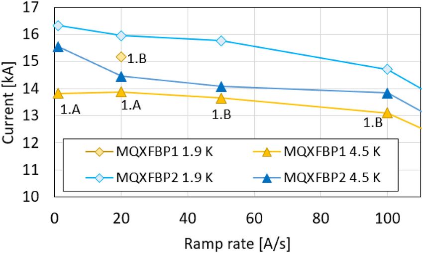
You can also read