Rendering Pearlescent Appearance Based On Paint-Composition Modelling
←
→
Page content transcription
If your browser does not render page correctly, please read the page content below
EUROGRAPHICS 2001 / A. Chalmers and T.-M. Rhyne                                                                             Volume 20 (2001), Number 3
(Guest Editors)

                       Rendering Pearlescent Appearance Based On
                              Paint-Composition Modelling

                                             Sergey Ershova , Konstantin Kolchina and Karol Myszkowskib

                                             a Keldysh    Institute for Applied Mathematics, Moscow 125047, Russia
                                                   b Max-Planck-Institut   für Informatik, Saarbrücken, Germany

         Abstract
         We describe a new approach to modelling pearlescent paints based on decomposing paint layers into stacks of
         imaginary thin sublayers. The sublayers are chosen so thin that multiple scattering can be considered across dif-
         ferent sublayers, while it can be neglected within each of the sublayers. Based on this assumption, an efficient
         recursive procedure of assembling the layers is developed, which enables to compute the paint BRDF at interac-
         tive speeds. Since the proposed paint model connects fundamental optical properties of multi-layer pearlescent
         and metallic paints with their microscopic structure, interactive prediction of the paint appearance based on its
         composition becomes possible.

1. INTRODUCTION                                                                         analytical model of multi-layer paints, which satisfies these
                                                                                        requirements.
In the world of global competition, products developed by
different makers are often of similar quality and function-                                In our approach, we decompose each layer of the paint
ality, and the appearance of these products often deter-                                film into thin imaginary sublayers such that within each layer
mines their commercial success. Therefore, the prediction                               we can neglect multiple scattering. Thus, we assume that the
of a product’s appearance using computer graphics tools be-                             subsequent bounces of light scattering always occur in dif-
comes of primary importance at the early design stages. This                            ferent layers, which makes possible analytical calculation of
proves to be a nontrivial task for modern coatings such as                              the scattering function for every layer. The model for scatter-
metallic and pearlescent paints, which change appearance                                ing functions of sublayers is based on the statistical approach
with viewing and illumination directions. Because of rich-                              and describes precisely light scattering within paint includ-
ness of visual effects, which can be obtained using such                                ing iridescent and pearlescent phenomena. We determine the
paints, new coatings are often custom designed for a particu-                           scattering function of each of the paint layers from that of the
lar product (e.g., a car model) with regard for its shape char-                         sublayers using the doubling method [10, 11] and then find
acteristics. To make such a design efficient, rendering of a                            the BRDF of the whole paint film using the adding method
finished product must be performed at interactive speeds pre-                           [10, 11, 30].
dicting its appearance based on the composition of designed
                                                                                           The boundaries between sublayers are only imaginary,
paint. This involves modelling of light interaction within
                                                                                        thus reflection and refraction on such boundaries should not
the paint structure taking into account multiple scattering,
                                                                                        be taken into account. Obviously, this is not the case for the
which is computationally expensive when performed at the
                                                                                        actual boundaries between layers of paint, which exist in a
atomic level of paint elements (Figure 1 shows an example
                                                                                        multi-layer paint.
of the cross-section through a complex paint structure). So
the problem is to find a higher level paint reflectance func-                              It turns out that by introducing further simplifications to
tion (BRDF-like), which somehow takes into account mul-                                 the model of light scattering between flakes, an efficient ana-
tiple scattering and makes possible editing paint composi-                              lytic approximation of BRDF can be found. The error intro-
tion parameters as shown in Figure 1 within the technologi-                             duced by the simplifications is negligible for flake densities,
cally feasible limits. In this paper, we propose a novel semi-                          which are used in practice (while neglecting multiple scatter-

°c The Eurographics Association and Blackwell Publishers 2001. Published by Blackwell
Publishers, 108 Cowley Road, Oxford OX4 1JF, UK and 350 Main Street, Malden, MA
02148, USA.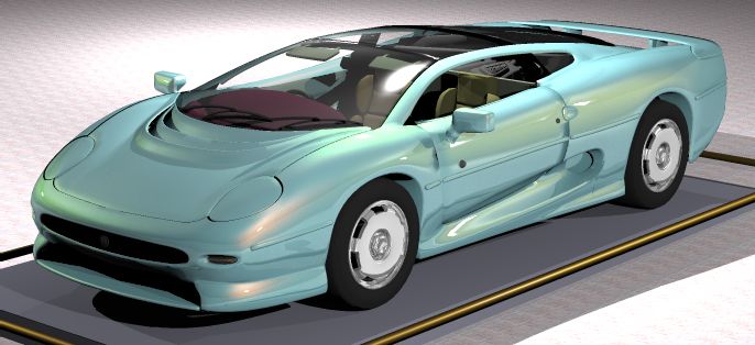
Ershov, Kolchin and Myszkowski / Pearlescent Paints

                                                                          simplistic assumptions such as isotropic properties of film
                                                                          [17], uniform illumination within film [18], limited number
                                                                          of film layers to just one [17, 2], or fixed parallel orientation
                                                                          of all flakes in respect to the paint surface [3]. On the other
                                                                          hand, solutions involving participating media computations
                                                                          in the 3D environments of arbitrary shapes, e.g., clouds [21],
                                                                          are too general, and thus are computationally too expensive
                                                                          for our application (a good survey of similar solutions han-
                                                                          dling multiple scattering can be found in [22]).
                                                                             There are many solutions applying a direct simulation
                                                                          of light propagation within the material structure, which is
                                                                          modelled in macroscopic scale. These methods essentially
                                                                          make it possible to model all the optical effects important
                                                                          in our application, and some of these methods were specif-
                                                                          ically developed to handle pearlescent and iridescent phe-
                                                                          nomena [8, 23]. However, these methods are very expensive
                                                                          in terms of computations because a huge number of light
Figure 1: An example of the multi-layer paint structure. The              rays must be traced within the material to obtain statistically
paint composition tree is shown on the left. Some nodes are               meaningful approximation of the material reflectance. The
expanded displaying their internal structure and the struc-               methods that require the explicit geometric modelling of ma-
ture of their constituents. The paint composition parameters              terial structure [1,29,8,23] have an additional disadvantage
shown in the tree are the subject of changes during the paint             that the model must be often reconfigured when paint com-
design. For more details on technological issues concerning               position is changed during its design stage. This problem
paint components refer to [2, 3].                                         can be partially alleviated by implicit modelling of the ma-
                                                                          terial structure, which can be described in statistical terms
                                                                          [9,6,7] (i.e., in terms of the probability that a ray hits a flake
ing at all results in a significant error). This analytic model           when travelling a certain distance within the material). Since
is specially tuned for ensembles of smooth platelets† , and               our application requires BRDF approximations at interactive
it is quite accurate when flakes are embedded in transpar-                speeds, the approaches involving low-level simulations of
ent (not turbid) medium, i.e., pigment density is low. This               scattering with the implicitly or explicitly modelled geom-
is true for real metallic paints which are transparent to em-             etry are too slow for our purposes. Also, prior to the actual
phasise “flake effects” like sparkling [19], and thus this fast           simulation, these methods usually make it difficult to qual-
model is very helpful in interactive paint design.                        itatively predict BRDF changes as a result of paint compo-
                                                                          nent modifications performed by the paint designer.
1.1. Previous Work                                                           Such qualitative predictions of BRDF changes are usu-
                                                                          ally possible for theoretical reflectance models, such as the
In recent years, many papers relevant to the modelling of
                                                                          Cook-Torrance model [4], or even the more advanced HTSG
pearlescent and metallic paints appeared in the CG literature,
                                                                          model [12]. These models are quite efficient in terms of
however, a majority of them does not fit well to our applica-
                                                                          computations and approximate the BRDF of typical materi-
tion. For example, the approaches based on direct measur-
                                                                          als well. However, some parameters required by these mod-
ing of BRDF characteristics [5, 27] preclude any prediction
                                                                          els do not have any physical interpretation [28]. Because of
of the designed paint appearance before it actual manufac-
                                                                          this lack of correspondence between the model parameters
turing. Also, the models of interference developed for ren-
                                                                          and the material parameters, it is fairly hard to manufacture
dering of soap froth [24, 16], oil slicks [24], and pearls [20],
                                                                          the actual material with properties matching those predicted
which describe well physical phenomena for continuous thin
                                                                          by the theoretical reflectance models. In the context of our
films are not suitable to account for light scattering between
                                                                          application, the existing theoretical models are not flexible
multiple pearlescent flakes of relatively small size that are
                                                                          enough to properly model the BRDF of materials whose mi-
embedded in a binder and surrounded by pigment particles
                                                                          croscopic structure differs significantly from the one based
and metallic flakes (see Figure 1). Because of similar rea-
                                                                          on the microfacets.
sons we could not apply other solutions relying on too many

                                                                          1.2. Discussion
† The assumption that most of scattered light is in a narrow cone
usually holds. Nishita et al. used a similar observation to accelerate    Since the existing methods are not suitable for our ap-
the Monte-Carlo computation of multiple scattering in their cloud         plication because of efficiency problems (direct simulation
modelling solution [21].                                                  methods) or assumptions of oversimplified material structure

                                                                                           °
                                                                                           c The Eurographics Association and Blackwell Publishers 2001.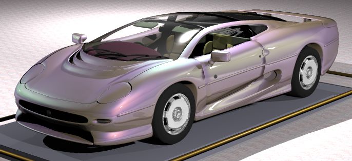
Ershov, Kolchin and Myszkowski / Pearlescent Paints

(theoretical models), we decided to develop our own theo-                          we introduce scattering functions, which are somewhat more
retical model tailored specifically for materials featuring the                    convenient than BRDF. In Section 3, the doubling/adding
structure similar to the one shown in Figure 1. Our approach                       method (computation of BRDF of a thick layer from that
is based on the adding or doubling techniques developed for                        of a thin layer of the same material) is derived, and then in
computation of scattering in planetary atmospheres [15, 10,                        Section 4 it is applied to multi-layer paints. In Section 5, we
11], which apply light transport equations transformed to a                        calculate BRDF of a thin layer analytically assuming that
form that is specific for these applications. In a sense, Hanra-                   scattering agents are flakes (platelets with interference coat-
han and Krueger approach [9] is the closest to ours because                        ing) and spherical particles. In Section 6, we derive the “fast
it is also based on the light transport theory. However, in                        model” (an analytic approximation to the BRDF of paint).
[9] transport integral equations were solved with the help of                      In Section 7, we derive a model for “micro-appearance” (in
Monte-Carlo method while we employ direct grid methods                             terms of [19]) of paint, i.e., we describe sparkling as the fluc-
which are faster. A form of adding technique (called subsur-                       tuation of luminance due to reflection by individual flakes
face compositing in [6]) was applied to reduce the complex-                        observed from the close distance. Finally, we present some
ity of ray tracing within multi-layer films by providing an an-                    results obtained using our approach and we conclude this
alytical solution for such films in [6,23]. It was assumed that                    paper.
all layers are different, and every layer has a simple homoge-
neous structure, so that its reflectance and transmittance can
be analytically computed. In our solution, the adding step                         2. SCATTERING OPERATORS
just complements the doubling step which produces multi-
                                                                                   Let Iinc be radiant power (of incident light) emitted in a given
ple imaginary layers within a single real layer. This makes
                                                                                   direction per unit solid angle per a unit surface area (so that it
possible accounting for multiple scattering in complex me-
                                                                                   differs from radiance by the cosine of a ray’s direction with
dia and formulating a novel analytic approximation of BRDF
                                                                                   the surface normal) falling on the object surface, and let Ir
for pearlescent and metallic paints.
                                                                                   and It be the same quantities reflected from and transmitted
   Our approach can be classified as a continuous media ap-                        through the object. The transformation of these quantities
proach like [10, 11, 18, 21], which has also some deficiencies                     defines the reflection and transmission operators R and T
such as an assumption of independence between scattering
events which does not hold in practice. For example, light
scattered by a flake may then be reflected by another flake                                               Ir (ϑ, ϕ) = (RI inc ) (ϑ, ϕ),
(or substrate) and then hit the first flake again. Despite that                                           It (ϑ, ϕ) = (TIinc ) (ϑ, ϕ)
the probability of such an event is low, it may be essential
in some cases, which we cannot be sure a priori.‡ Another
                                                                                   whose corresponding kernels Rand T (scattering functions)
simplification in our approach relies on considering just the
                                                                                   can be expressed as:
total area of flakes per unit paint volume instead of separate
treatment of the flake size and density. This means that our
BRDF can be identical for few large flakes and many small                                             R
                                                                                       Ir (ϑ, ϕ) = R R(ϑ, ϑ0 , ϕ − ϕ0 )I inc (ϑ0 , ϕ0 ) sin ϑ0 dϑ0 dϕ0
flakes, which is a good approximation only within certain
                                                                                       It (ϑ, ϕ) = T (ϑ, ϑ0 , ϕ − ϕ0 )I inc (ϑ0 , ϕ0 ) sin ϑ0 dϑ0 dϕ0
limits imposed on the maximum size and density of flakes.
                                                                                                                                                         (1)
   Yet another phenomenon that clearly depends on the flake                                  0    0
                                                                                   where (ϑ , ϕ ) are the polar and azimuth angles of the inci-
size is granularity or fluctuations of luminance [3, 19]. As
                                                                                   dent ray in respect to the surface normal, and (ϑ, ϕ) are those
flakes get larger, individual flakes become visible as tiny
                                                                                   of the scattered ray. Note that because we assume isotropic
shining mirrors (sparkling effect [19]). The sparkles can be
                                                                                   paint properties the kernels just depend on the difference
understood as a texture of paint, and this texture essentially
                                                                                   of azimuths of incident and scattered rays, which makes
depends on viewing and illumination conditions, thus being
                                                                                   equation (1) simpler than its more general counterpart for
an example of a BTF [5]. We can compute and visualise this
                                                                                   non-isotropic surfaces. Also, note that the following relation
texture; but again this is an approximation valid for not too
                                                                                   between used by us reflection kernel and commonly used
large flakes of not too high density.
                                                                                   BRDF holds:
   1.3 Overview
   Now let us describe the paper organisation. In Section 2,                               R(ϑ, ϑ0 , ϕ − ϕ0 ) = BRDF(ϑ, ϑ0 , ϕ − ϕ0 ) cos ϑ.

                                                                                   and that our scattering functions do not take into account
‡ Stochastic media approach based on implicit modelling of ma-                     spatial dependence, which is possible because we do not
terial structure [7,9] has similar drawbacks; e.g., it is possible that            consider such dependence on the macro level and operate
some rays pass freely through a certain space region, while others                 thin sublayers on the micro level, where consideration of sin-
undergo scattering in the same region.                                             gle scattering is enough.

°
c The Eurographics Association and Blackwell Publishers 2001.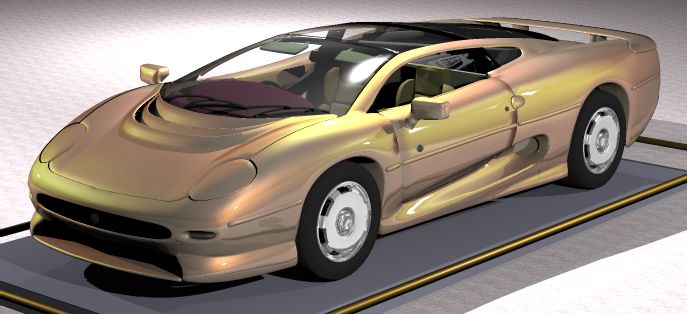
Ershov, Kolchin and Myszkowski / Pearlescent Paints

3. DECOMPOSITION OF LAYERS                                                   We assume the following layer numbering convention:
Let us consider two adjacent layers 1 (left) and 2 (right) with          •   0-th substrate
reflection and transmission operators R+         +
                                         k and Tk for illumi-            •   1-st paint film
                            −        −                                   •   Fresnel boundary between 1-st and 2-nd paint films
nation from the left, and Rk and Tk for illumination from
the right. We must distinguish these cases: imagine a perfect            •   ...
mirror whose rear side is absolutely black. Then R+ is the               •   Fresnel boundary between M − 1th and M th paint films
identity operator, while R− = 0. However, for a symmetric                •   M th paint film
layer, these operators coincide.                                         •   Fresnel boundary between the M th paint film and air
                                                                         •   A Fresnel boundary between media with the refraction in-
   Let the incident light with angular distribution of energy
                                                                             dices η and η0 is a somewhat special layer as described in
Iinc comes from the left. By tracing how it bounces between
                                                                             Section 3.
layers and summing all components, we find that the scatter-
ing operators for the two-layer system are                                  The scattering operators R(η,η0 ) , T(η,η0 ) for light going
                                                                         from medium with refraction index η0 into that with refrac-
                        − +       − + −1 +
                                                                         tion index η are
          R+      +
           1+2 = R1 + T1 R2 (1 − R1 R2 ) T1
           +      +       − + −1 +                             (2)
          T1+2 = T2 (1 − R1 R2 ) T1
                                                                                                               1−rη0 η (ϑ0 )
                                                                             T(η,η0 ) (ϑ, ϑ0 , φ)       =         ³ ϑ δ(φ)
                                                                                                                 sin                    ´
and, for illumination from the right,                                                                                          0
                                                                                                              ×δ ϑ − arcsin( ηη sin ϑ0 )                (5)
                                                                                            0                 rη0 η (ϑ0 )  ¡      0¢
                                                                             R(η,η0 ) (ϑ, ϑ , φ)        =       sin ϑ δ(φ)δ ϑ − ϑ
          R−      −     + −       + − −1 −
           1+2 = R2 + T2 R1 (1 − R2 R1 ) T2
           −      −       + − −1 −                             (3)
          T1+2 = T1 (1 − R2 R1 ) T2
                                                                         where rη0 η is the Fresnel reflectance for unpolarised light,
                                                                         and δ is the delta-function.
   Note that (2) and (3) are mathematically equivavalent to
formulas for reflection and transmission of two combined                    Each paint film itself, i.e., without interfaces, is naturally
slabs in Section 3.4 of [30].                                            assumed to be homogeneous and thus symmetric, so we can
                                                                         compute its reflection and transmission operators by means
   It is noteworthy that because layers are isotropic and the
                                                                         of the doubling method. It enables to compute scattering
operators actually depend on the absolute value of difference
                                                                         operators for a layer based on that for a thin layer of the
in ϕ, the real-valued cosine FFT drastically reduces time of
                                                                         same material. The latter is a rather simple problem (e.g.,
computation for each of the compositions of operators in (2)
                                                                         refer to [9]) because in a thin layer we can neglect multiple
and (3).
                                                                         scattering.
   In the derivation of equations (2) and (3), reflection and
refraction by the boundary between layers was not consid-                   Let us subdivide the layer into a power of two imagi-
ered. But if the layers are made of different materials, re-             nary sublayers whose thickness h0 is small enough to neglect
flection/refraction occurs at their boundary. In such a case,            multiple scattering. Then let us compute scattering operators
we must split our system into three layers: the first one is             for such sublayers, and apply iteratively equations (2) and
the former layer 1 with refraction index η1 , then comes a               (3) (note that due to the symmetry of sublayers, operators
layer made of infinitesimally thin films of substances 1 and             are the same for light going forward and backward):
2; then comes the former layer 2 with refraction index η2 .
No reflection/refraction occurs at the boundary between lay-
                                                                                        R2h = Rh + Th Rh (1 − Rh Rh )−1 Th
ers; instead, it occurs for the middle layer. Thus, we treat the                                                                                        (6)
middle layer as a plain Fresnel boundary with reflection and                            T2h = Th (1 − Rh Rh )−1 Th
transmission operators (5). Then we can compute the oper-
ators for the whole system using equations (2) and (3): first               Thus, as the result of n such iterations we obtain the op-
we put together layers 1 and 2, and then add to them layer 3.            erators for the paint film of thickness 2n h0 . The procedure
                                                                         is repeated for each of M paint films, and the corresponding
                                                                         scattering operators are computed. Also, we compute oper-
4. MULTI-PAINT COATING                                                   ators for the Fresnel boundaries between paint films using
Let us consider a paint coating made of M layers which cover             equation (5), and for the Lambertian substrate using equa-
the substrate layer featuring the Lambertian reflection with             tion (4). Now we must combine these operators to compute
albedo rs :                                                              scattering in the whole coating. To do so, we use the adding
                                                                         method which is based on another version of equations (2)
                                                                         and (3).
                                          rs
                 Rs (ϑ, ϑ0 , ϕ − ϕ0 ) =      cos ϑ             (4)           Let us denote the reflectance of substrate surface (illumi-
                                          π

                                                                                                °
                                                                                                c The Eurographics Association and Blackwell Publishers 2001.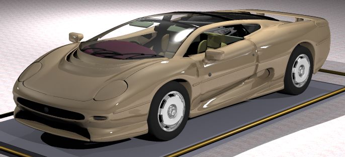
Ershov, Kolchin and Myszkowski / Pearlescent Paints

nated from the paint side) as Rs (we do not need its trans-                           In absence of multiple scattering the scattering operator
mittance or reflectance for light going from behind the sub-                       for an ensemble of flakes equals that for a single flake av-
strate), the reflection and transmission operators of the m-th                     eraged over its size and orientation, and scaled by the flake
paint film as Rm and Tm (because of the symmetry, we do                            density (like for rough surface built of facets [4]). Orienta-
not need to distinguish between operators marked with “+”                          tion of flakes is described by the distribution P(β) of angle β
and “−”). Let the reflection operator of the system:                               between the normal vectors to flake and paint surfaces. The
                                                                                   probability of finding a flake with a given orientation is
  substrate + 1st film +...+ mth film + interface between the
                     mth and m + 1th films
                                                                                                               Pr = 2πP(β)sinβdβ
be denoted as R[0,m] ≡ R+  [0,m] (we do not need to consider
the transmission and reflection operators for light going from                        The derivation of reflectivity can be found in Section 7.
behind the substrate). Applying equations (2) and (3), we can                      Here we linearise (36) in h, and assume that the refraction in-
add to this system the m + 1-th paint film:                                        dices of the binder and outer medium are equal, because here
                                                                                   we do not need to account for transformation at the Fresnel
                                                                                   boundary (it is accounted for in (8)):
           R0[0,m+1] = Rm+1 + Tm+1 R[0,m]
                        ³                ´−1
                       × 1 − Rm+1 R[0,m]     Tm+1                       (7)           Rh (ϑ, ϑ0 , φ)       =               1
                                                                                                                 hDhSi 4 cos ϑ0 r p (αR )P(βR )
                                                                                      Th (ϑ, ϑ0 , φ)       =       1
                                                                                                                 sin³ϑ δ(ϑ − ϑ0 )δ(φ) ´
                                                                                                                       hDhSih1−t p i(ϑ)               (9)
and then after considering an interface between the m + 1-th                                                     × 1−       cos ϑ0
and m + 2-th paint films, we obtain                                                                                          1
                                                                                                                   +hDhSi 4 cos ϑ0 r p (αT )P(βT )

                                                                                      Here αR (αT resp) is the angle between the incident ray
          R[0,m+1] = R(ηm+1 ,ηm ) + T(ηm ,ηm+1 ) R0[0,m+1]                         and the bisector of incident and reflected (transmitted) rays;
                       ³                             ´−1                           βR (βT resp.) is the angle between the paint normal and the
                     × 1 − R(ηm ,ηm+1 ) R0[0,m+1]                                  bisector of incident and reflected (transmitted) rays, see (14);
                            ×T(ηm+1 ,ηm )                               (8)        D is the flake density, and hSi is the mean flake area. Then,
                                                                                   hSih1 − t p i(ϑ) is the extinction cross-section (averaged over
   This is an iterative process of successive adding layers                        flake orientation) for the incidence angle ϑ:
to the top of the existing stack. Starting it with R[0,0] ≡ Rs
and applying (7) and (8) M times, we end with the reflection                                                    R π/2                R π/2
operator of the whole paint coating. Obviously, ηM+1 ≡ 1                            h1 − t p i(ϑ)      =       2 0 dβP(β) sin β 0 dφ(1 − t p (α1 )) cos α1
                                                                                                                  R π/2               R π/2
(refractive index of air). At each step, Rm and Tm are com-                                                    +2 0 dβP(β) sin β 0 dφ(1 − t p (α2 )) cos α2 ;
puted using the doubling method (6).                                                cos α1             ≡       cos β cos ϑ + sin β sin ϑ cos φ
                                                                                    cos α2             ≡       |cos β cos ϑ − sin β sin ϑ cos φ|
                                                                                                                                                 (10)
5. SCATTERING OPERATORS FOR A THIN LAYER
                                                                                      Even for a thin layer ray path might be long for light at
For a thin layer we can neglect multiple scattering, so the to-                    grazing angles, so our formulae will fail forcos ϑ0 ≤ O(h).
tal scattering is a linear “superposition” of scattering by all                    The correct form of kernels in such a narrow interval is rather
its components. Therefore we must just sum up their “par-                          inessential for integral doubling equations; it is only neces-
tial” operators.                                                                   sary that they be finite, which can be ensured by clipping
                                                                                   dangerous denominators in (9)
5.1. Scattering by flakes
                                                                                                                            ½
Flakes are assumed to be smooth (specularly reflecting)                                1        ∆(ϑ0 )                          1,   if ϑ0 < ϑmax
                                                                                             7→        ,         ∆(ϑ0 ) ≡                            (11)
platelets of random orientation. They may have interference                          cos ϑ 0    cos ϑ0                          0,   if ϑ0 ≥ ϑmax
coating, thus wave theory must be employed to compute re-
flectance and transmittance of flake r p (α) and t p (α) as func-
                                                                                   5.2. Scattering by pigment particles
tions of angle α between ray and flake normal. This is a rou-
tine problem of interference optics; for a simple coating it                       Pigment particles are assumed to be spherical and isotropic,
was solved in [3]. We assume that the flake diameter is much                       so their scattering depends only on the angle γ between inci-
greater than light wavelengths, so r p (α) and t p (α) are inde-                   dent and scattered rays. The phase function g(γ) obeys Mie
pendent of the flake size. Outside flake bodies we use ray                         or (for very tiny particles) Rayleigh laws [14]. Also, empiri-
optics, because the distance between flakes is much greater                        cal laws like Henyey-Greenstein phase function [13] can be
than light wavelengths.                                                            used. For any such function

°
c The Eurographics Association and Blackwell Publishers 2001.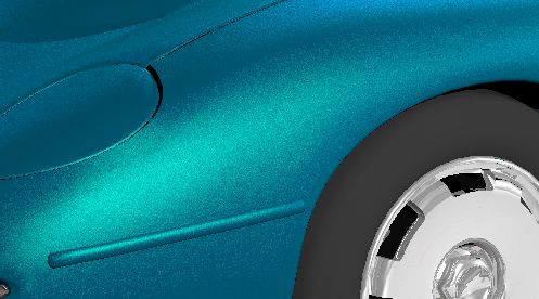
Ershov, Kolchin and Myszkowski / Pearlescent Paints

                                                                                or averaged scattered energy) yield more or less similar esti-
                                            ∆(ϑ0 )                              mates:
       Rh (ϑ, ϑ0 , φ)    =     hDpigm σsc cos ϑ0 g(γR );
                                      0
                 0             δ(ϑ−ϑ )δ(φ)
       Th (ϑ, ϑ , φ)     =       ³ sin ϑ                 ´
                                         ∆(ϑ)
                               × 1 − cos ϑ hDpigm σext
                                                                     (12)                                       π/2 − ϑmax
                                                                                            h≤                                                           (15)
                                                     0
                                                 ∆(ϑ )
                                                                                                  κ+      ∑     Dpigm σext + ∑ DhSi
                               +hDpigm σsc cos ϑ0 g(γT )                                               pigments                   flakes

   Some light misses particles and runs out of layer unscat-                    where ϑmax is the cutoff angle from (11).
tered. The fraction of energy that remains in the direction
of incident beam (i.e., is not scattered) is determined by the                  6. FAST MODEL OF BRDF OF A TWO-LAYER
extinction cross-section σext , which is the first term in the                     PAINT
above transmission operator. Here Dpigm is the pigment den-
sity, σsc is the scattering cross-section, γR (γT resp.) is the                 Two-layer paint, made of substrate (color base) covered with
angle between the incident and reflected (transmitted) rays,                    a single paint film, is the simplest metallic paint that has
derived in (14). The problem with light traversing a layer at                   its basic visual and composition features. Many real paints
grazing angles is solved using the clipping approach (11).                      are actually two-layer ones, or can be well approximated by
                                                                                them (e.g., neglecting multiple layers of a transparent resin
                                                                                used to protect the paint from weathering). One can treat
5.3. Attenuation in the binder                                                  two-layer paint as a paint with flakes and pigments sepa-
                                                                0
In case of a thin layer, the attenuation e−κh/ cos ϑ is small                   rated: flakes are in the top layer and pigments are in the bot-
(here κ is absorption in the binder). So for the sake of sim-                   tom layer (substrate which is a solid paint).
plicity we neglect the attenuation for scattered light, and only                   We will also consider a special kind of flakes called
consider it for unscattered light.                                              “mirror” which are the simplest from simulation point of
                                                                                view, because can be completely characterised by their color
5.4. Scattering operator for a thin paint layer                                 (reflectance), and their internal structure can be ignored.
                                                                                Such flakes do not exist in the real world, so they can be
Combining the above effects: scattering by flakes (9) with                      considered just as a “limiting case” for metal chips, or flakes
clipping (11), scattering by Rayleigh particles (12) and at-                    with such interference coating that its reflectance and trans-
tenuation in the binder we have                                                 mittance are nearly independent of the angle of incidence
                                                                                (this can be achieved using a special coating).
                                    ³
                             ∆(ϑ)                                                  The two-layer paint has actually yet one “hidden” layer:
 Rh (ϑ, ϑ0 , φ)      =   h cos ϑ        1
                                        4 DhSir p (αR¢)P(βR )                   the Fresnel boundary between air and binder. So, using the
                             +Dpigm σsc g(γR )³                                 adding method described in Section 4, we can compute the
          0                           0            ∆(ϑ)
 Th (ϑ, ϑ , φ)       =   sin©ϑ δ(ϑ − ϑ )δ(φ) 1 − h cos ϑ
                           1
                                                                                paint reflectance Rp by combining the scattering operators
                                                               ª¢
                                 ³ − t p i(ϑ) + Dpigm σext + κ
                         × DhSih1                                               for all three layers:
                            ∆(ϑ)
                         +h cos ϑ 14 DhSir p (αT )P(βT )
                                                ¢                                                           ³          ´−1
                              +Dpigm σsc g(γT )
                                                            (13)                            Rp = R+ + T − Rs 1 − R− Rs     T+                            (16)

and
                                                                                where Rs is reflection operator of the substrate, and R(±) and
                                                                                T(±) are reflection and transmission operators of the layer
                                    0           0
      cos γR,T       ≡   q ϑ cos ϑ ∓ sin ϑ sin ϑ cos φ,
                         cos                                                    of flakes with the air-paint boundary. The Fresnel boundary
                           1±cos2 γR,T                                          must be considered only between the layer and air, so the
      cos αR,T       ≡         2       ,                             (14)       scattering operators are
                         ± cos ϑ−cos ϑ0
      cos βR,T       ≡      2 cos αR,T

                                                                                                                     −
  If there are several kinds of flakes, or pigments, we                                R+     =     R+
                                                                                                     interface + Tinterface Rfl
                                                                                                               −
sum their partial scattering operators (and extinction cross-                                       ×(1 − Rinterface Rfl )−1 T+   interface
sections).                                                                             T+     =     Tfl (1 − R−                −1 +
                                                                                                                interface Rfl ) Tinterface               (17)
                                                                                       R−     =     Rfl + Tfl R− interface
                                                                                                    ×(1 − Rfl R−              −1
                                                                                                                   interface ) Tfl
5.5. Criterion of thinness                                                                           −                      −
                                                                                       T−     =     Tinterface (1 − Rfl Rinterface )−1 Tfl
The intuitive criterion is that optical thickness is small. Vari-
ous quantitative implementations (e.g., concerning maximal                      where Rfl and Tfl are reflection and transmission operators

                                                                                                  °
                                                                                                  c The Eurographics Association and Blackwell Publishers 2001.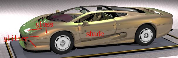
Ershov, Kolchin and Myszkowski / Pearlescent Paints

of layer with flakes without the air-paint boundary. Since it                        where αR and βR are given in (14), and the optical thickness
is symmetrical (no boundaries, so it does not matter from                            τ is given by
which side it is illuminated), we omit the “±” superscripts.
By combing (16) and (17) we obtain
                                                                                                                 κ + DhSih1 − t p i(ϑ)
                                                                                                        τ(ϑ) =                                        (21)
                                                                                                                        cos ϑ
     Rp = R+
          | interface
              {z }
                     gloss
                                                                                     6.2. Glitter component

                + T+          Rfl (1 − R−              −1 +
                                        interface Rfl ) Tinterface
                                                                                     Now let us substitute Rfl and Tfl from (20) into (17) and
                  | interface            {z                      }                   compute R(±) and T(±) . Reflectance by the Fresnel bound-
                                              glitter                                ary, as well as that by flakes, is rather weak, so we can ne-
                      ³           ´−1
                                                                                     glect their product. In this case, we obtain results similar to
                       −
                + T Rs 1 − R − Rs     T+                                 (18)
                  |        {z          }                                             those of Section 2 of [9]. Namely, transmittance is approxi-
                                   shade                                             mately specular because rays transmitted through a flake do
                                                                                     not change direction, while reflected rays go backward and
   It is remarkable that for every term of (18) the corre-                           do not contribute to the transmitted beam. Therefore, the dif-
spondence to the paint appearance attributes [19] (refer also                        fuse component in transmitted light is due to the 2nd order
to Figure 2) can be found: the first term (the Fresnel re-                           scattering, and by neglecting it we have an error up to O(h2 ).
flectance) corresponds to gloss, the second (reflection by                           Thus, scattering operators can be computed as:
flakes) to glitter, and the third (reflection by substrate) to
shade. Due to the roughness of painted surface the first term
                                                                                                                          1−rη (ϑ0 )
is not a purely specular operator, but exhibits some diffuse                            T + (ϑ, ϑ0 , ϕ)    ≈      e−hτ(ϑ)
                                                                                                                     ³      sin ϑ ³δ(ϕ)         ´´
properties as well (for discussion of rough dielectric surfaces                                                   ×δ ϑ − arcsin η1 sin ϑ0
refer to e.g., [26, 17]).                                                                                               0 1−r      (ϑ0 ) cos ϑ        (22)
                                                                                        T − (ϑ, ϑ0 , ϕ)    ≈      e−hτ(ϑ ) η2 1/η              δ(ϕ)
                                                                                                                                   ϑ0³ cos ϑ0 ´´
                                                                                                                     ³         sin
                                                                                                                        0
6.1. Scattering operator of a homogeneous layer with                                                              ×δ ϑ − arcsin η sin ϑ 1

     flakes
Applying equations (2) and (3) to a system made of the same                            R− (ϑ, ϑ0 , ϕ)     ≈      Rfl (ϑ, ϑ0 , ϕ)
                                                                                                                                    0
homogeneous material, but with one layer having infinites-                                                       +r(σ)e−2hτ(ϑ ) sin1 ϑ δ(ϑ − ϑ0 )δ(ϕ)
imal thickness, we derive a differential form of the “adding
                                                                                       R+ (ϑ, ϑ0 , ϕ)     ≈      rη (ϑ0 ) sin1 ϑ δ(ϑ − ϑ0 )δ(ϕ)
equations”:
                                                                                                                 +[1 − rη (ϑ0 )][1 − rη (ϑ)]
                                                                                                                              ϑ
                                                                                                                        2 cos ϑ̄ Rfl (ϑ̄ , ϑ̄, ϕ)
                                                                                                                    × ηcos              0

                             ∂R                                                                                                                     (23)
                             ∂h
                                  =       TRT,
                             ∂T                                          (19)
                             ∂h   =       (T + RR)T                                  where Rfl is given by (20), and ϑ̄0 and ϑ̄ are the angles after
                                                                                     refraction by the Fresnel boundary derived as:
where h is the layer thickness and
                                                                                                   ³          ´                     ³         ´
                                                                                       ϑ̄0 = arcsin η−1 sin ϑ0 ,         ϑ̄ = arcsin η−1 sin ϑ (24)
                                   1
                         R ≡ limh→0 Rh ,
                                   h
                                   1                                                 6.3. Shade component
                         T ≡ limh→0 (Th − 1)
                                   h
                                                                                     Let us evaluate the last term in (18), which represents the
correspond to the scattering operators for an infinitesimally                        substrate reflectance as observed through the binder with
thin layer, and they can be derived from (13). Solving these                         flakes:
equations with successive approximations similar to those
used in Section 5.1 of [9] we see that the scattering operators                                                 ³          ´−1
of a layer with flakes are approximately                                                          Rs,eff ≡ T− Rs 1 − R− Rs     T+                     (25)

                                                                                     where Rs is the substrate reflectance given by (4). The term
      Rfl (ϑ, ϑ0 , ϕ)        =             1
                                  DhSih 4 cos ϑ0 r p (αR )P(βR )                        ¡           ¢−1
                                           −[τ(ϑ0 )+τ(ϑ)]h                           Rs 1 − R − Rs      can be calculated by means of expansion
                             =    × 1−e
                                     [τ(ϑ0 )+τ(ϑ)]h                      (20)        in the Neumann series. After some simple though tedious
                 0                    −τ(ϑ0 )h − 12 h2 R2
      Tfl (ϑ, ϑ , ϕ)         =    e           e                                      calculations one obtains

°
c The Eurographics Association and Blackwell Publishers 2001.
Ershov, Kolchin and Myszkowski / Pearlescent Paints
³ ´−1 1
Rs 1 − R− Rs = Rs τ(ϑ) ≈ DhSi[1 − t p (ϑ)] (29)
1 − 2rs Q
and therefore for mirror flakes or when we can neglect angu-
where
lar dependence of reflection and transmission, τ is a constant,
so (28) further simplifies and takes the form
Z
Q≡ R− (ϑ0 , ϑ, ϕ) sin ϑ0 cos ϑ0 dϑ0 sin ϑdϑdϕ (26)
rs,eff
Rs,eff ≈ [1 − rη (σ)][1 − rη (ϑ)] × cos ϑ (30)
Substituting the result in (25) gives π
where rs,eff is the effective albedo and can be computed as
1 rs
Rs,eff (ϑ, ϑ0 , ϕ) =
1 − 2rs Q π η−2 e−2hτ
Z Z rs,eff ≡ rs ³ −2τh
´
− 0 1 − rs DhSihr p 1−e + e−2hτ F(η)
× T (ϑ, ϑ , ϕ) cos ϑ sin ϑdϑdϕ 2τh
Z Z
× T + (ϑ, ϑ0 , ϕ) sin ϑ0 dϑ0 dϕ (27) and F is the averaged Fresnel reflectivity
Using approximation (22) and Helmholtz reciprocity
Z π/2
r1/η (ϑ̄) = rη (ϑ) (which can be derived directly from the
F(η) ≡ r1/η (ϑ) sin 2ϑdϑ (31)
Fresnel formulae), we can calculate the integrals of transmis- 0
sion operators, and substituting the above expressions into
(27) we obtain If, besides that, flakes are translucent so r p + t p = 1, (29)
yields τ = DhSir p then the expression for rs,eff simplifies to:
Rs,eff (ϑ, ϑ0 , ϕ) = [1 − rη (ϑ0 )][1 − rη (ϑ)]
η−2 e−2hτ
×e−h[τ(ϑ )+τ(ϑ̄)]
¯0
rs,eff = rs ¡ ¢ (32)
1 − 12 rs 1 + e−2hτ [2F(η) − 1]
η−2 rs
× cos ϑ (28)
1 − 2rs Q π
6.4. BRDF of the whole paint coating
where, as usually, ϑ̄0 and ϑ̄ are the angles after refraction by
Combining (23) and (30), we obtain the scattering opera-
the Fresnel boundary, see (24).
tor, and then, dividing by cosine of the outgoing angle, the
According to (20), Rfl is only distinct from zero when β BRDF:
(refer to (14)) is of the order of variation of flake normal
vectors. But when flake’s normal is nearly parallel to paint
normal (i.e., β ≈ 0) then the angle of reflection ϑ is close to BRDF(ϑ, ϑ0 , ϕ) ≈ rη (ϑ0 )
1
δ(ϑ − ϑ0 )δ(ϕ)
the angle of incidence ϑ0 ; and also the angle α between ray cos ϑ sin ϑ
and flake normals is close to ϑ0 . Formally, one can derive [1 − rη (ϑ0 )][1 − rη (ϑ)]
+DhSih
from (14) that α ≈ ϑ0 ≈ ϑ in the region where the distribu- 4η2 cos ϑ̄0 cos ϑ̄
tion P is essentially distinct from zero. Replacing in (20) α
1 − e−[τ(ϑ )+τ(ϑ̄)]h
¯0
and ϑ with ϑ0 and substituting the resulting approximation ×
for Rfl into (26), we obtain after some algebra [τ(ϑ̄0 ) + τ(ϑ̄)]h
¡ ¢ ¡ ¢
×r p αR (ϑ̄, ϑ̄0 , ϕ) P βR (ϑ̄, ϑ̄0 , ϕ)
Z +[1 − rη (ϑ0 )][1 − rη (ϑ)]rs,eff
DhSih 1 − e−2τ(ϑ)h
Q ≈ r p (ϑ) sin 2ϑdϑ
2 2τ(ϑ)h
Z When calculating αR , (βR resp.), by means of (14), the
+
1
e−2hτ(ϑ) r1/η (ϑ) sin 2ϑdϑ angles ϑ and ϑ0 must replaced with the angles ϑ̄0 and ϑ̄ after
2 refraction by the paint surface, which can be derived using
(24).
In the case of small variation of flake orientation (10) ap-
proximately yields h1 − t p i(ϑ) ≈ (1 − t p (ϑ)) cos ϑ, thus if In the case of mirror flakes, or when we can neglect the
we neglect absorption in the binder (i.e., κ=0), and then the angular dependence of flake reflectance and transmittance
optical thickness (21) can be approximated as (and thus optical thickness), this becomes
°
c The Eurographics Association and Blackwell Publishers 2001.Ershov, Kolchin and Myszkowski / Pearlescent Paints
by Fresnel paint-air boundary and pigments in paint. Re-
1 flected light is also attenuated en route to observer, so the
BRDF(ϑ, ϑ0 , ϕ) ≈ rη (σ) δ(ϑ − ϑ0 )δ(ϕ)
cos ϑ sin ϑ reflected energy which reaches for the eye pupil is
+[1 − rη (ϑ0 )][1 − rη (ϑ)]rs,eff
+[1 − rη (ϑ0 )][1 − rη (ϑ)]
0
E = I × [1 − rη (ϑ0 )][1 − rη (ϑ)]e−z[τ(ϑ̄ )+τ(ϑ̄)]
−2DhSihr p 0
1−e × cos αr p (cos α) × S cos ϑ̄ (34)
×
8η2 cos ϑ̄0 cos ϑ̄
¡ ¢ where the first line describes attenuation in paint and the sec-
×P βR (ϑ̄, ϑ̄0 , ϕ) (33)
ond line describes reflectance by flake. Here I is illumination
of the paint surface, ϑ0 is the angle of incidence, ϑ̄0 is the
The first component in (33) is reflectance by Fresnel
angle of incidence after refraction by the paint-air boundary
boundary, which ideally contains delta-functions (i.e., it is
(24), r p (α) is reflectance of flake surface, S is the flake sur-
purely specular). In fact, the paint surface is not ideally
face area, rη is the Fresnel reflectance of paint-air boundary,
smooth, so the Fresnel reflectance is smoothed over some
and flake depth z is a random variable uniformly distributed
angular interval. Typically this can be modelled with gaus-
in [0, H]. The optical thickness τ along ray path is given in
sian bell-shape.
(21).
The above approach can be also applied to a multi-layer
The light beam specularly reflected by a flake platelet is
paint. Each layer may contain several kinds of flakes, but we
diverging cone of angle equal to the angulat size of light
omit this case because of complexity of the corresponding
source. Therefore, luminance of all sparkles in the pixel is
formulae.
(see [31]):
7. SPARKLES (PAINT TEXTURE)
1 1
L = E
Under directional illumination, paint surface looks as π∆2 Σ cos ϑ
“dusted” with tiny shining sparkles, usually differing in [1 − rη (ϑ)][1 − rη (ϑ0 )]r p (cos α) cos α
color from the “background” paint. These fluctuations of lu- = I
π∆2 Σ cos ϑ cos ϑ̄0
minance arise due to light reflection directly by flakes. Flake 0
is seen as a “sparkle” if it reflects light directly into observer × ∑ Se−[τ(ϑ̄)+τ(ϑ̄ )]z
(35)
all sparkles
[31] which occurs when its normal vector is close to the bi-
sector of the illumination and observation directions. In [31] The sum is over all N sparkles which we assume to be
we show that in case of a “nearly point” light source varia- statistically independent because they correspond to differ-
tion of the flake’s normal makes cone with solid angle ent flakes.
π∆2 cos ϑ Subtracting from luminance (35) its expectation, we get
d2n f = the fluctuation δL. During rendering, we first compute the
4η cos αcos ϑ̄
total luminance of a pixel in usual way (using some local
where α ≡ αR is the angle of incidence/reflection counted or global illumination model), and then we add the fluc-
from flake’s surface, see (14), ∆ is the angular radius of light tuation of luminance (in which case only point and paral-
source, η is the refraction index of the binder, ϑ is the angle lel lights are taken into account). If there are several light
of observation and ϑ̄ is the angle of observation after refrac- sources, the flake luminance and its mean is a sum for all
tion by the paint-air boundary (24). point and parallel lights. The random variables for different
light sources are independent, because sparkling caused by
The probability for the flake normal to be within the above these light sources affects different flakes.
cone is P(β)d 2 n f , where β ≡ βR is the angle between paint’s
and flake’s normal vectors, see (14). Therefore expected From (35) one can calculate reflectance by ensemble of
number of sparkles in a pixel is: flakes (assuming interreflections are weak) needed in Sec-
tion 5.1. This is just the average of the random variable (35),
cos ϑ see [31]:
hNi = πΣ∆2 · DHP(β)
4η2 cos α cos ϑ̄
where Σ is the area of pixel projection onto the paint sur- BRDF = DhSih
face, D is the density of flakes, and H is the paint thickness. [1 − rη (ϑ)][1 − rη (ϑ0 )]
×
The “actual” number of sparkles N is a Poisson deviate with 4η2 cos ϑ̄0 cos ϑ̄
mean hNi. 0
1 − e−[τ(ϑ̄)+τ(ϑ̄ )]h
×
Each sparkle is illuminated with incident light attenuated [τ(ϑ̄) + τ(ϑ̄0 )]h
°
c The Eurographics Association and Blackwell Publishers 2001.Ershov, Kolchin and Myszkowski / Pearlescent Paints
Figure 2: Basic appearance attributes – gloss, glitter and
shade.
Figure 3: Conventional solid paint with the gloss and shade
attributes similar to those shown in Figures 2 and 5a. But
×P(β)r p (cos α) (36) solid paint does not have glitter.
8. RESULTS
The paint model described in this paper is a principal com-
ponent of an interactive system for designing paint appear-
ance based on its composition. At first, the paint composition
must be input using the paint editor. Parameters of flakes,
pigment particles, binder are specified for every paint layer.
The values of the parameters can be interactively changed
within the technologically feasible limits. Based on these pa-
rameters and the designed paint structure, the BRDF of cur-
rently specified paint is computed using our multi-layer paint Figure 4: Two-layer pearlescent paint with the substrate’s
model. This BRDF is then used by the parametrized ray trac- color different from that of the paints shown on Figures 2
ing [25] for rendering of a number of predefined views of an and 5a.
coated object. For every view and for every pixel all data
required by the local illumination model is pre-computed
and stored to a disc file prior to the paint design session.
This makes possible very rapid update of pixel luminance
Glitter is a complex attribute determined by flakes, i.e., the
based on the BRDF of currently designed paint. The render-
metallic or dielectric (mica) platelets, optionally coated with
ing time is constant and depends on the image resolution,
titanium dioxide (interference coating) [2,3]. For example,
but it is independent of the complexity of scene geometry.
the hue of glitter depends on the thickness of the interfer-
For example, the whole processing of BRDF computation
ence layer of pearlescent flakes (refer to Figure 5), and the
for a two-layer pearlescent paint using the fast paint model
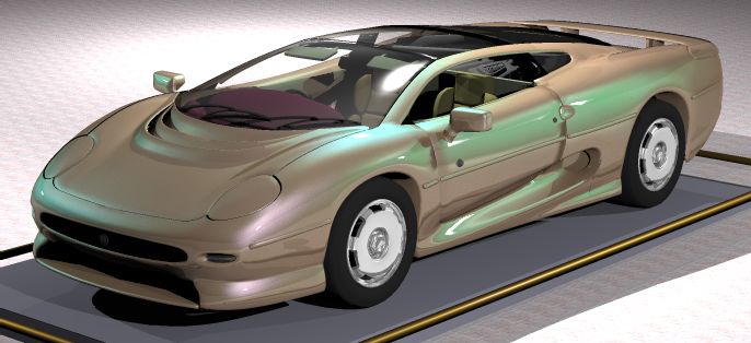
color of metallic flakes (Figure 6). Figure 5a (correspond-
(described in Section 6) and rendering an image of resolu-
ing to "pearl.bmp" on the conference CD) and "metal.bmp"
tion 640 x 480 takes about 0.14 seconds on a Pentium III,
on the conference CD show the appearance of two paints
500 MHz processor. If the full version of the paint model
that differ only by the kind of flakes - one with pearlescent
(described in Sections 4 and 5) is used then the analogous
and the other with metallic flakes (and the average color of
processing requires about 0.5–5 seconds depending on the
the pearlescent flake corresponds to the color of the metallic
type of updated paint parameter. The computation require-
flake). For metallic paints the hue of glitter does not change
ments increase with the complexity of the paint structure.
with the viewing direction, while such differences can be
For example, a three-layer paint with two types of flakes and
readily observed for pearlescent paints (refer to Figures 2
two types of pigment particles requires about 1–9 seconds.
and 5a showing images of the same car rendered for two
As it can be seen, the response times provided by our sys-
different viewing directions). The spread of glitter depends
tem are reasonable for interactive paint design. As the final
on the variation of flakes orientation, and the glitter inten-
result of such paint modelling a record of paint composition
sity depends on the flakes density and their mean surface
is generated for its manufacturing.
area. An interesting effect is sparkling (refer to Figure 6)
Figure 2 shows basic appearance attributes [19] such as which becomes noticeable when the painted surface is close
shade, gloss, and glitter which are affected by changing paint to the observer. Sparkling mostly depends on the geome-
composition. The shade and gloss attributes are common to try of flakes, their density, and area variation. Even more
the so-called solid (conventional) paints (refer to Figure 3). complex paint appearance can be obtained for multiple-layer
The extent of gloss depends mostly on the roughness of the paints as shown in Figure 7. Note that all images shown in
paint surface. Shade depends on the color of layer substrate Figures 2-7 were obtained at interactive speeds including the
(refer to Figure 4). paint BRDF modelling.
°
c The Eurographics Association and Blackwell Publishers 2001.Ershov, Kolchin and Myszkowski / Pearlescent Paints
9. CONCLUSIONS AND FUTURE WORK
In this paper, we proposed a novel model of multi-layer
pearlescent and metallic paints, which derives paint’s BRDF
based on its composition. The model is computationally ef-
ficient which makes possible interactive design of paint ap-
pearance by changing its composition. Since we use the
parametrized ray tracing as a high quality rendering tool,
the appearance of coated objects of arbitrary geometric com-
plexity can be easily designed at interactive speeds.
In the current paint model we assumed that flakes are
ideal platelets featuring specular reflection, however, mod-
ern paints may include flakes of other kinds - such as, dia-
mond prisms. Also, we assumed that pigment particles are
spherical and obey Mie scattering theory, however, real pig-
ments may have more complex shapes, in which case numer-
ically derived scattering diagrams should be used. We left as
future work the extensions of our model required to handle
Figure 5: Two-layer paint with pearlescent flakes of various
such complex paint components.
thickness of interference coating a) 200 nm, and b) 43 nm
(all other paint parameters are the same on a and b).
Acknowledgements
The authors express their deep gratitude to Dr. A. Fujimoto
for his help, interest and valuable remarks.
References
1. B. Cabral, N. Max and R. Springmeyer. Bidirectional
Reflection Functions From Surface Bump Maps. Pro-
ceedings of SIGGRAPH 87, 273–281.
2. P. Callet. Pertinent Data for Modelling Pigmented Ma-
terials in Realistic Rendering. Computer Graphics Fo-
rum (1996), 15(2), 119–128.
Figure 6: Sparkling effect. 3. P. Callet. Physically Based Rendering of Metallic
Paints and Coated Pigments. Visualization and Mod-
elling (ed. R. Earnshaw et al.), Academic Press, 1997,
287–301.
4. R. L. Cook and K. E. Torrance. A Reflectance Model
for Computer Graphics, ACM Transactions on Graph-
ics (1982), 1(1), 7–24.
5. K.J. Dana, B. van Ginneken, S.K. Nayar and J.J. Koen-
derink. Reflectance and Texture of Real-world Sur-
faces. ACM Transactions on Graphics (1999), 18(1),
1–34.
Figure 7: A multi-layer paint with two layers containing 6. J. Dorsey and P. Hanrahan. Modeling and Rendering of
pearlescent flakes with different densities. Flakes differ by Metallic Patinas. Proceedings of SIGGRAPH 96, 387–
thickness of the interference coating. 396.
7. J. Dorsey, A. Edelman, J. Legakis, H. Wann Jensen and
H.K. Pedersen. Modeling and Rendering of Weathered
Stone. Proceedings of SIGGRAPH 99, 225–234
8. J.S. Gondek, G.W. Meyer and J.G. Newman. Wave-
length Dependent Reflectance Functions. Proceedings
of SIGGRAPH 94, 213–220.
°
c The Eurographics Association and Blackwell Publishers 2001.Ershov, Kolchin and Myszkowski / Pearlescent Paints
9. P. Hanrahan and W. Krueger. Reflection from Layered Interference Phenomena in Realistic Image Synthesis,
Surfaces Due to Subsurface Scattering. Proceedings of 1st Eurographics Workshop on Photosimulation, Real-
SIGGRAPH 93, 165–174. ism and Physics in Computer Graphics (1990), 185–
194.
10. J.E.Hansen. Radiative Transfer by Doubling Very Thin
Tayers, Astrophys. J., (1969) 155, 565–574. 25. C. H. Sequin and E. K. Smyrl. Parametrized Ray Trac-
ing. Proceedings of SIGGRAPH 89, 307–314.
11. J.E.Hansen and L.Travis. Light Scattering in Planetary
Atmospheres. Space Science Reviews (1974), 16, 527– 26. J. Stam. Diffraction Shaders. Proceedings of SIG-
610. GRAPH 99, 101–110.
12. X.D. He and K.E. Torrance and F.X. Sillion and D.P. 27. A. Takagi, H. Takaoka T. Oshima, and Y. Ogata Accu-
Greenberg. A Comprehensive Physical Model. Pro- rate Rendering Technique Based on Colorimetric Con-
ceedings of SIGGRAPH ‘91, 175–186. ception. Proceedings of SIGGRAPH 90, 263–272.
13. L.G.Henyey and J.L. Greenstein. Diffuse Radiation in 28. G.J. Ward. Measuring and Modelling Anisotropic Re-
the Galaxy. Astrophys. J. (1941), 93, 70–83. flection. Proceedings of SIGGRAPH 92, 265–272.
14. H.C. Hulst. Light Scattering by Small Particles, Wiley, 29. S.H. Westin, J.R. Arvo and K.E. Torrance. Predicting
N.Y. (1957). Reflectance Functions From Complex Surfaces, Pro-
ceedings of SIGGRAPH 92, 255–264.
15. H.C.Hulst and K.Grossman. The Atmospheres of Venus
and Mars (Ed. J.C. Brandt and M.E. McElroy). 30. M. Pharr and P. Hanrahan. Monte Carlo Evaluation of
NewYork: Gordon and Breach. Non-Linear Scattering Equations For Subsurface Re-
flection. Proceedings of SIGGRAPH 2000, 75–84.
16. I. Icart and D. Arques. An Approach to Geometrical
and Optical Simulation of Soap Froth. Computers & 31. S. Ershov, A. Khodulev, and K. Kolchin. Simulation
Graphics (1999), 23(3), 405–418. of sparkles in metallic paints. Proceedings of Graph-
icon’99, 121–128.
17. I. Icart and D. Arques. An Illumination Model for a
System of Isotropic Substrate – Isotropic Thin Film
with Identical Rough Boundaries. 10th Eurographics
Rendering Workshop, (June 1999), 260–272.
18. P. Kubelka and F. Munk. Zeits. Tech. Physik (1931), 12,
593.
19. C.S. McCamy. Observation and measurement of the ap-
pearance of metallic materials. Part I. Macro appear-
ance. COLOR research and application (1996), 21,
292–304; Part II. Micro appearance. COLOR research
and application (1998), 23, 362–373.
20. N. Nagata, T. Dobashi, Y. Manabe, T. Usami and S.
Inokuchi. Modelling and Visualization for a Pearl-
Quality Evaluation Simulator. IEEE Transactions on
Visualization and Computer (1997) 3(4), 307–315.
21. T. Nishita, E. Nakamae and Y. Dobashi. Display
of Clouds and Snow Taking Into Account Multiple
Anisotropic Scattering and Sky Light. Proceedings of
SIGGRAPH 96, 379–386.
22. F. Perez, X. Pueyo and F.X. Sillion. Global Illumination
Techniques for the Simulation of Participating Media.
8th Eurographics Rendering Workshop, (June 1997),
309–320.
23. M. Schramm, J. Gondek and G. Meyer. Light Scat-
tering Simulations using Complex Subsurface Models.
Graphics Interface’97, 56–67.
24. B.E. Smits and G. Meyer, Newton’s Colors: Simulating
°
c The Eurographics Association and Blackwell Publishers 2001.You can also read