RESTORATION OF STORMWATER INFILTRATION BASIN PERFORMANCE
←
→
Page content transcription
If your browser does not render page correctly, please read the page content below
RESTORATION OF STORMWATER
INFILTRATION BASIN PERFORMANCE
Richard Brunton and Andrew Brough (Pattle Delamore Partners Ltd)

ABSTRACT
Stormwater infiltration basins form a key part of the suite of low impact urban design
devices to treat and dispose of urban stormwater runoff. These basins may suffer a
reduction in performance with time, either as a result of improper construction or some
step change, such as effects relating to an earthquake. In this paper several methods
and tools available for remediation of stormwater infiltration basins that exhibit reduced
performance are discussed, with reference to relevant case studies in the Christchurch
area.

The case studies presented cover a range of remediation techniques, including surface
aeration and complete replacement of topsoil and underlying drainage media. In one
case a complete loss of performance was incurred following discharge of 200,000 liters of
milk and beer into the infiltration basin during one of the Christchurch earthquakes. In
other cases infiltration basins exhibited very low infiltration rates and poor drainage,
potentially as a result of poor initial construction. The remediation techniques in these
cases include the construction of drainage trenches and aeration of topsoil. The analysis
and assessment techniques used for establishment of the cause of poor performance,
together with validation of performance post remediation, are also discussed in this
paper.

KEYWORDS
Infiltration basin, remediation, stormwater design

PRESENTER PROFILE
As a graduate engineer at Pattle Delamore Partners Ltd, Richard has been working in the
field of stormwater management for 3 years. Richard has experience in the design and
construction management of stormwater treatment devices including infiltration basins.

1     INTRODUCTION
Infiltration basins are one of the key elements from a suite of Low Impact Urban Design
Devices which treat and dispose of urban stormwater runoff. These are particularly
suitable to the area in and around Christchurch with overly permeable gravels.
Infiltration basins use filtration as a means of removing sediment and contaminants. It is
expected that these basins will suffer a reduction in performance over time associated
with the deposition of sediments in the basin.

Soon after construction, a number of infiltration basins have been found to have rates of
infiltration which do not meet the design, or consented, rates. This has generally been as
a result of improper construction, although excess sediment loads from the construction
of houses has also been attributed to the poor performance. The discharge of liquids,
other than rainwater, as occurred on a site in Christchurch during one of the earthquakes
also resulted in the failure of an infiltration basin.

8th South Pacific Stormwater Conference & Expo 2013
This paper demonstrates that there are several methods and tools available for
remediation of poor performing basins. Three case studies are presented that
demonstrate the range of remediation techniques, including surface aeration and
complete replacement of topsoil and underlying drainage media.

2        INFILTRATION BASIN CONSTRUCTION
Typically an infiltration basin will be designed with a base of river run gravels extending
down to natural free draining gravels underlying 150 to 250 mm of topsoil infiltration
media. Where the depth to free draining gravels is significantly below the base of the
basin an underdrainage system may be incorporated. This underdrainage will typically
discharge into a soakage chamber extending down to the free draining gravels.

Previously infiltration media was made up of a mixture of topsoil and Grade 2A sand.
However more recently a mixture of topsoil, sand and compost has been used. These
are usually combined at a ratio of 3:6:1 (topsoil:sand:compost) with a moisture content
of around 25%. This ratio may vary depending on the desired infiltration rate and nature
of the topsoil. For instance a sandier topsoil may require less sand compared with a silty
topsoil.

Care must be taken not to over mix the infiltration media components as this may break
up the natural “clods” resulting in poor drainage through the topsoil. For example the
use of rotary hoes should be avoided when combining the components. Once mixed the
infiltration media top soil is placed on the floor and sides of the basin and minimally
compacted (to the extent necessary to allow sowing of grass). Vehicle movements on
the basin floor and sides should always be avoided to prevent over-compaction of the
infiltration media. Once the media is in place the basin is generally grassed with
hydroseed. Figure 1 shows a typical cross section of an infiltration basin with under
drainage.

Infiltration basins will perform best when full grass cover is established before any
stormwater is discharged into the basin. Typically the basin should be constructed at
least two months before the site is commissioned for use and the stormwater system is
connected into the basin. This also allows for natural settling of the media layer and
allows for the grass to establish so that the surface is less prone to erosion and scour
once the basin is commissioned.

                                  Figure 1: Typical infiltration basin design
8th   South Pacific Stormwater Conference & Expo 2013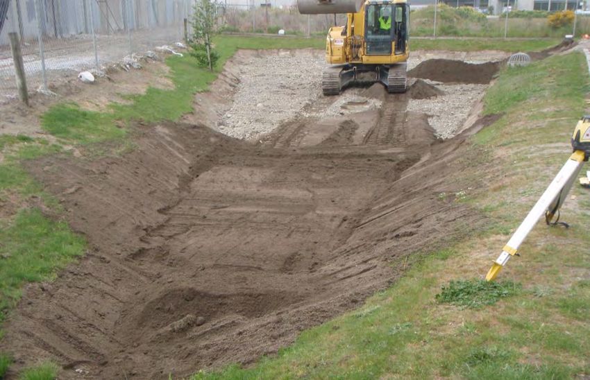
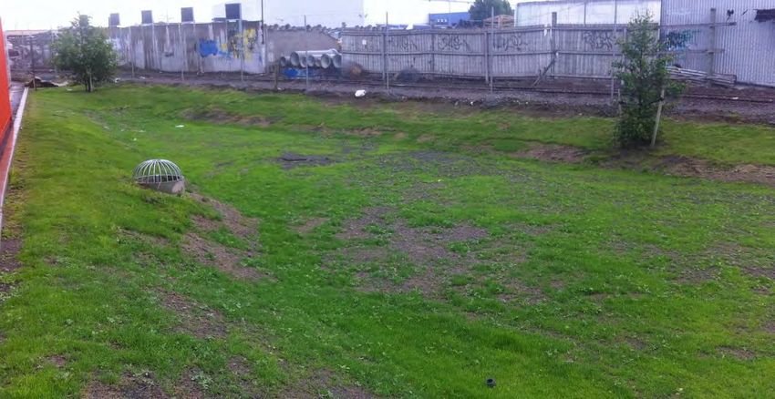
Typical fully installed cost per m2 of basin area is approximately $100 - $130/m3 of
storage. The main cost consideration is whether an under drainage system is required.
An under drainage system requires additional excavation, drainage pipe and a discharge
point such as a soakage chamber. Regular basin maintenance includes grass mowing,
cleaning out sediment from stormwater sumps and removing any debris and litter from
the basin. Environment Canterbury typically specifies in the consent an infiltration rate
through the media that needs to be met. Historically this has been between 20 and 50
mm/hr as measured using a double ring infiltrometer, but more recently has been
relaxed to between 12 and 112 mm/hr. Double ring infiltrometer tests are commonly
used to determine the infiltration rate of a soil media. It is commonly accepted that
double ring tests can overestimate rates by up to 40 % (US EPA 1991).

3     CASE STUDIES
3.1      INDUSTRIAL STORAGE HANDLING SITE
In 2009 a 220 m3 stormwater infiltration basin was constructed at a large warehouse and
distribution facility in southwest Christchurch. Stormwater from the sites car parking and
truck maneuvering area is collected via sumps and conveyed to an infiltration basin. The
shallow underlying stratum of the basin is relativity impermeable so an underdrainage
system was incorporated into the design. The basin was constructed with 250 mm of
topsoil media overlying 400 mm of river-run gravels. A trench was constructed below the
river-run gravels and was fitted with NOVAFLO™ pipe to collect and discharge treated
stormwater into a soakage chamber.

3.1.1    BASIN PERFORMANCE AND REMEDIATION
The infiltration basin was commissioned for use in 2009. Infiltration testing was carried
out prior to commissioning using a double ring infiltrometer test. The results of the test
showed that the average soakage rate of the basin was around 40 mm/hr. The basin
was commissioned for one year with acceptable soakage rates and healthy grass cover.
In the 4 September 2010 earthquake approximately 200,000L of liquids split from broken
containers within the warehouse facility. As an emergency response this liquid was
discharged into the infiltration basin. The liquid which included milk and beer was
pumped out of the basin within a few days following the earthquake.

Once all of the liquids were pumped out of the basin significant amounts of residual liquid
remained within the media layer. A strong odor was also noticed confirming that there
were still significant amounts of liquids trapped within the media layer. The infiltration
media was immediately replaced with clean media. It was initially thought that only the
infiltration media would be affected by the liquids and that no works were required on the
underlying gravels or under drainage system.

In the subsequent months following the replacement of the media reduced infiltration
capacity was observed within the basin. Significant ponding for long periods of time after
a storm event was observed followed by grass die off. Figure 2 shows the basin
approximately 6 months after the earthquake. The reduced infiltration rates did not
comply with the conditions of the stormwater discharge consent and therefore remedial
action was required.

8th South Pacific Stormwater Conference & Expo 2013
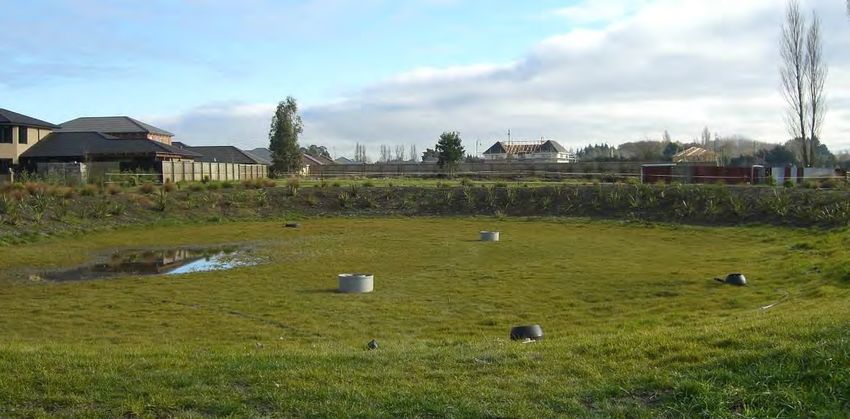
Figure 2: Infiltration basin after topsoil replaced
Aeration was initially carried out within the media as it was suspected that the media that
was re-laid immediately after the earthquake may have been over compacted. In this
case soil aeration was considered to be a significantly cheaper option than replacing the
media layer. In this case a turf aerator for sports fields was considered suitable. Figure
3 shows a photograph of a similar aerator.

                                            Figure 3: Turf aerator
The aeration of the basin resulted in no notable increase in infiltration rates and the basin
condition continued to decline. The media layer appeared to be uniform and therefore it
was considered that further aeration at different depths within the media would also be
ineffective.

A subsequent investigation was carried out to determine the extent of the remediation
works required within the basin. Cost limitations meant that an investigative approach
8th South Pacific Stormwater Conference & Expo 2013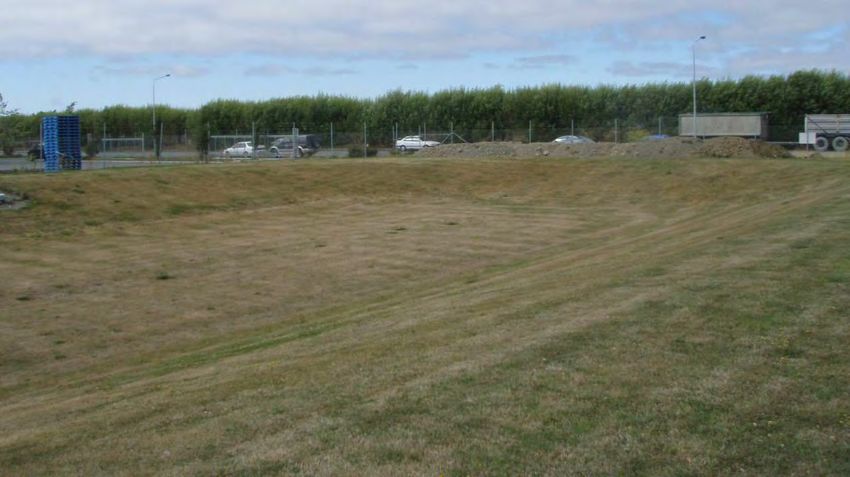
was required to isolate the cause of reduced infiltration and replace only what was
required. Double Ring Infiltrometer tests were carried out at the top of the basin (topsoil
layer), intermediate layer (top 150 mm of topsoil scrapped off), and at the gravel layer
(all topsoil removed). Figure 4 shows the results of the infiltrometer tests for all three
layers. Note that all three tests were carried out at different locations so that each test
was not influenced by the water that drained through the soil profile from an earlier test.
Topsoil
Intermediate
Gravel
Figure 4: Double ring infiltrometer test results
Initial rates during the tests indicated that the infiltration rate was high at the topsoil
layer at around 60 – 120 mm/hr. However once the ultimate infiltration rate was
reached it was noted that the topsoil rate was very low (around 10 mm/hr). The
intermediate test indicated similar results with initially good rates decreasing to very low
rates within a short amount of time. The final test involved removing all topsoil and
testing the rate of the underlying river-run gravel. The results showed that the ultimate
rate of the gravel was around 30 mm/hr which is considered very low. The river-run
gravel used at this site was expected to have a soakage rate of between 500 – 1000
mm/hr.
During the site investigation a test pit was also dug down to the underdrainage system.
The gravel within the drainage trench and geotextile material was confirmed to be in
good condition. It was noted during this test pit that there was a strong odor coming
from the test pit. It was concluded that the underlying gravel layer had very low soakage
capacity. Possible causes for this could include:
Blocking of gravel pore space by spilled liquids during earthquake, (milk?)
Compaction of gravel layer from earthquake shaking,
Compaction of gravel during the first replacement of topsoil layer,
Combination of all factors.
Based on the site investigation it was decided that the basin gravels would need to be
replaced. The following remediation strategy was adopted:
Excavate materials down to under drainage layer to [spoil],?
Flush underdrainage lines to ensure that the underdrainage was not blocked,
Relay clean river-run gravels,
Relay infiltration media,
Hydroseed.
8th South Pacific Stormwater Conference & Expo 2013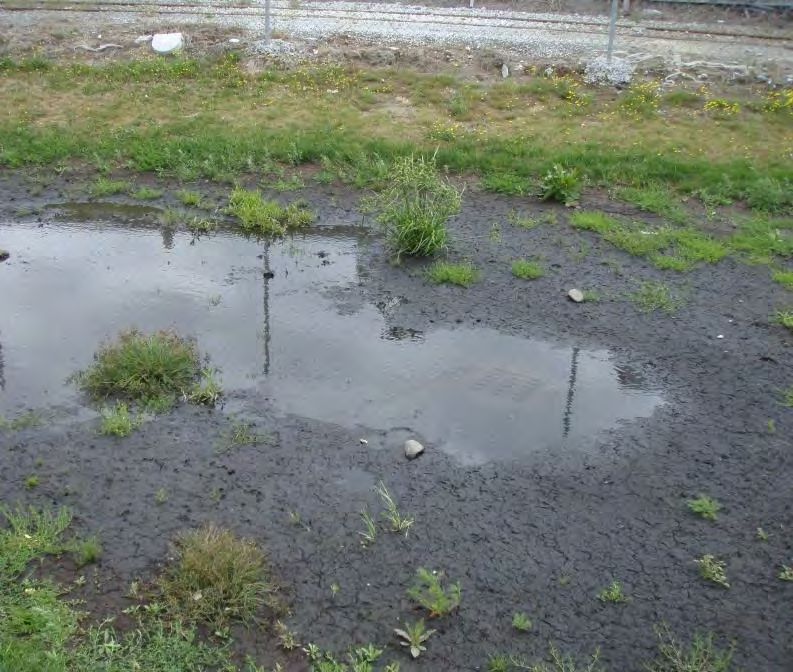
Figure 5 shows the remediation works in progress with the infiltration media being placed
over the new free draining gravels.

                            Figure 5: Basin infiltration media being placed
3.1.2    RESULTS
Infiltration testing using double ring infiltrometer has confirmed the basin is now
operating as expected with an average infiltration rate of around 47 mm/hr. Healthy
grass growth was more difficult to achieve because the basin was in active use during the
hydroseeding and grass growing period. This emphasises the importance of establishing
healthy grass cover before a basin is commissioned. The basin is now compliant with
regional council consent conditions. Figure 6 shows the basin around one month after
remediation. The photo shows non-uniform grass cover after hydroseeding as a result of
discharges into the basin during the growth period. Infiltration testing was carried out a
further one month after the photo was taken once further grass cover was established.

8th South Pacific Stormwater Conference & Expo 2013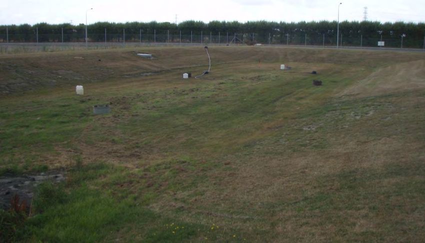
Figure 6: Infiltration basin 1 month after remediation

3.2      RESIDENTIAL SUBDIVISION
Infiltration basins are a common form of stormwater treatment and disposal for
Christchurch residential subdivisions. Typically residential basins collect runoff from
roads and driveways. In 2004 a 300 m3 infiltration basin was constructed within a new
subdivision in North West Christchurch. Because of sufficient soakage rates in the
underlying gravel strata an underdrainage system was not incorporated into the design.
The infiltration media consisted of a mixture of topsoil and Grade 2A sand.

3.2.1    BASIN PERFORMANCE AND REMEDIATION
Upon the commissioning of the basin a double ring infiltrometer test found that the
infiltration rate through the media was very low. Extended periods of stormwater
ponding within the basin also indicated low infiltration rates. Inspection of test pits dug
within the topsoil layer indicated that the 150 mm thick topsoil layer was very tight. This
was most likely as a result of over compaction during the construction phase of the basin.
It was determined that a soil aerator could be used to break up the topsoil layer.

After the aeration double ring infiltrometer testing was carried out. The infiltration
testing results showed that the infiltration rate was still very poor at less than 2 mm/hr.
During the test it was noted that the basin had water ponded over an area of the basin,
as shown in Figure 7, which indicates that there is very poor infiltration in that area.

8th South Pacific Stormwater Conference & Expo 2013
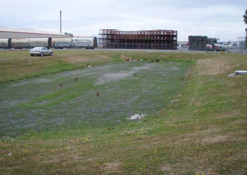
Figure 7: Basin after installation of trench
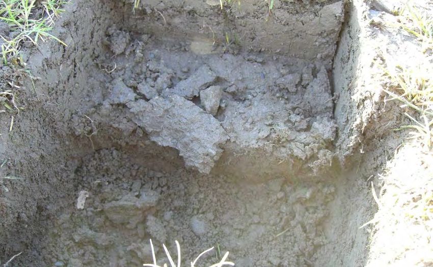
Due to the low infiltration rate further test pits were dug to see if there was any obvious
reason for the poor infiltration rates. As shown in Figure 8, the test holes were
characterised has having 100 mm of loose sandy loam over approximately 50 mm of
tight sandy loam on loose sandy gravel. It was evident from the test holes that the tight
layer was the reason for the poor infiltration rate.
Figure 8: Basin topsoil profile
It would appear from the test holes that the initial aeration of the topsoil did not
penetrate the whole media layer, leaving a small depth, but significant layer, which water
failed to penetrate. A second attempt at aeration was carried out ensuring that the depth
of the aerator was set below the tight layer. This ensured that the tight layer was broken
up and aerated.
8th South Pacific Stormwater Conference & Expo 2013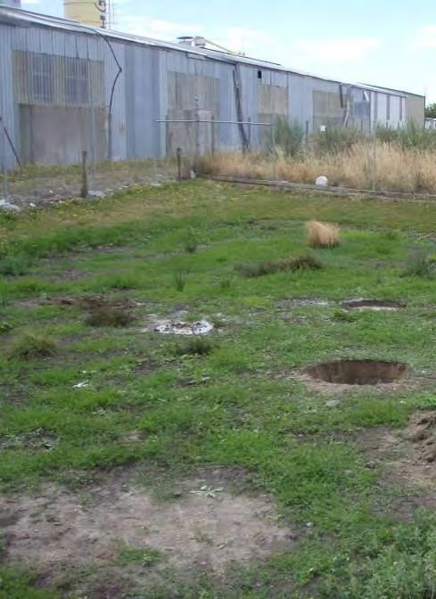
3.2.2    RESULTS
Final testing of the infiltration basin was carried out using a flooded basin test. The test
method involves filling the basin to a depth of approximately 200 mm and then recording
the rate of decline in the water level, for a minimum duration of two hours, or until the
infiltration rate remains the same for readings taken over a period of one hour. Such a
full scale test is considered to be of a higher standard than a double ring infiltrometer
test. The measurements made during the test showed that the final infiltration rate of
the basin was 24 mm/hr. Healthy grass cover also indicates that the basin is now
performing as designed.

3.3      INDUSTRIAL MANUFACTURING SITE
The third case study looks at an infiltration basin constructed in February 2007 to treat
runoff from a large industrial site which operates a feed mill. Because the underlying
gravel stratum was considered free draining no under drainage system was incorporated
into the design.

3.3.1    BASIN PERFORMANCE AND REMEDIATION
Initially after construction of the basin was completed the basin showed healthy grass
cover. Due to the low rainfall during, and soon after construction, the infiltration
performance of the basin was unknown. Figure 9 shows the basin in a healthy looking
state three months after construction.

                                    Figure 9: Basin after construction

Once rainfall increased after the summer months significant ponding and grass die off
was observed in the basin. Infiltration testing was carried out in July 2007 which showed
very low infiltration rates of 0 - 6 mm/hr in four different locations within the basin.

Soil aeration similar to that described in the previous case study was carried out to break
up the soil structure and increase infiltration rates.        Subsequent infiltration tests
confirmed rates between 10 and 80 mm/hr in four different locations within the basin. As
8th South Pacific Stormwater Conference & Expo 2013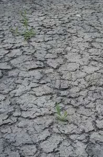
an average these rates were considered acceptable and complaint under the regional
council consent. During the infiltration basin test observations were noted that sediment
buildup was apparent at the basin inlets. Figure 10 taken in 2008 shows the beginnings of
grass die off at the basin inlet due to sediment deposition.

                           Figure 10: Double ring basin test after aeration
Following the aeration of the topsoil layer the basin condition continued to deteriorate in
the form of grass die off and water ponding. During testing, the topsoil rates were shown
to be sufficient and therefore it was assumed that water was unable to pass below the
topsoil layer during large rainfall events. The mostly likely cause of this blockage is the
presence of a low permeability layer immediately below the bottom of the river-run
gravel layer.

In order to get water past this low permeability layer into the more free draining strata a
gravel trench was installed in the middle of the basin that extended down further into the
natural gravels. Figure 11 shows a conceptual sketch of how the gravel trench would
provide a better flow path of treated water into free draining strata.

                          Topsoil                                River-Run
                                                                 gravels

                                                                             Impermeable
                                                                             layer

                                                       Gravel trench

                                Figure 11: Cross section of gravel trench

8th South Pacific Stormwater Conference & Expo 2013
The installation of the gravel trench alleviated the water ponding issue within the basin.
Once the gravel trench was installed grass die off around the basin inlets continued to be
an on-going issue. Caking of the grass was also noted as shown in Figure 12. It was
determined that this caking was caused by sediments entering the basin from the
catchment. These sediments were mainly particles of grains and other organic material
from the feed mill processing operation and sediments from trucks and vehicles. To
reduce the amount of sediments conveyed into the basin the stormwater sump
maintenance frequency was changed to monthly cleaning instead of the previous three
monthly. This allowed the sediment containment volume within the stormwater sumps to
be cleaned out more frequently and reduce amount of sediment entering the basin.
Gravel trench
Figure 12: Basin after installation of trench
3.3.2 RESULTS
The basin is now performing as expected and adheres to regional council consent
requirements. The installation of the gravel trench and increasing the frequency of
stormwater sump maintenance has greatly reduced grass die off and caking within the
basin. Figure 13 shows the basin condition after remediation works.
8th South Pacific Stormwater Conference & Expo 2013Figure 13: Recent photo of basin 4 CONCLUSIONS Remediation of poor performing infiltration basins can be undertaken in a number of ways. Proper investigation is required to determine the cause of performance issues. Investigative techniques include double ring infiltrometer testing, site observations and test pitting. The causes for poor performing infiltration basins can be caused by over compacting of topsoil during construction, events associated with earthquakes or other spillage incidents, insufficient treatment of the stormwater and poor maintenance of the infiltration basin. There are a number of options available for remediating poor performing basins. Aeration has proven to be somewhat effective although may require several aerations before desired infiltration is achieved. Aeration must also be carried out over the entire media depth to breakup all compacted layers. Adequate specifications and contractor supervision is required to ensure the media is not over compacted. The media should be placed and pressed gently with back of the excavator bucket; natural settling will then generally achieve the desired compaction. Gravel trenches have proven to be effective where a low permeability layer is stopping water from infiltrating into free-draining gravels. Regular maintenance of stormwater sumps is important to prevent fine sediment from blocking the media. Three monthly to monthly clean outs of stormwater sumps in sediment intensive sites would be recommended. Based on the above case studies using investigative methods and regularly maintenance ultimately provide a more cost effective solution than replacing the whole system. 8th South Pacific Stormwater Conference & Expo 2013
ACKNOWLEDGEMENTS
REFERENCES
J.O. Sai, D.C. Anderson 1991: State-of-the-Art Field Hydraulic Conductivity Testing of
Compacted Soils. United States Environmental Protection Agency.

Christchurch City Council 2003: Waterways, Wetlands and Drainage Guide. Part B Design

8th South Pacific Stormwater Conference & Expo 2013
You can also read