Sample gas pumps P2.x, P2.8x Installation and Operation Instructions
←
→
Page content transcription
If your browser does not render page correctly, please read the page content below

Gas Analysis

                                                              Sample gas pumps

                                                                           P2.x, P2.8x

           Installation and Operation Instructions
                                                                   Original instructions

BE420001   Bühler Technologies GmbH, Harkortstr. 29, D-40880 Ratingen
06/2021      Tel. +49 (0) 21 02 / 49 89-0, Fax: +49 (0) 21 02 / 49 89-20
                    E-Mail: analyse@buehler-technologies.com
                     Internet: www.buehler-technologies.com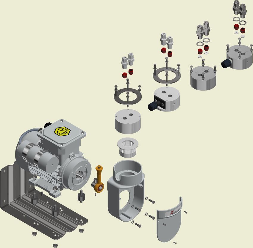
Bühler Technologies GmbH, Harkortstr. 29, D-40880 Ratingen
Tel. +49 (0) 21 02 / 49 89-0, Fax: +49 (0) 21 02 / 49 89-20
Internet: www.buehler-technologies.com
E-Mail: analyse@buehler-technologies.com

Read this instruction carefully prior to installation and/or use. Pay at-
tention particularly to all advises and safety instructions to prevent in-
juries. Bühler Technologies can not be held responsible for misusing
the product or unreliable function due to unauthorised modifications.

All rights reserved. Bühler Technologies GmbH 2021

Document information
Document No..........................................................BE420001
Version......................................................................... 06/2021
P2.x, P2.8x

Contents
1     Introduction.....................................................................................................................................................................................................................   2
      1.1   Intended use .........................................................................................................................................................................................................        2
      1.2 Product key............................................................................................................................................................................................................         3
      1.3 Scope of delivery ..................................................................................................................................................................................................            4
      1.4 Product description ............................................................................................................................................................................................                4
2     Safety instructions......................................................................................................................................................................................................... 5
      2.1 Important advice ................................................................................................................................................................................................. 5
      2.2 General indication of risk ................................................................................................................................................................................. 5
3     Transport and storage .................................................................................................................................................................................................. 7
4     Installation and connection ........................................................................................................................................................................................ 8
      4.1 Requirements for the set-up location ........................................................................................................................................................... 8
            4.1.1   Outdoor installation........................................................................................................................................................................... 8
      4.2 Mounting............................................................................................................................................................................................................... 9
      4.3 Special condition moist sample gas .............................................................................................................................................................. 9
            4.3.1   Alteration of hanging pump bodies ............................................................................................................................................. 10
      4.4 Connecting the sample gas line.................................................................................................................................................................... 10
      4.5 Electrical connections ....................................................................................................................................................................................... 11
5     Operation and control ................................................................................................................................................................................................. 12
      5.1 Switching on the sample gas pump ............................................................................................................................................................ 12
      5.2 Operating the sample gas pump................................................................................................................................................................... 13
6     Maintenance.................................................................................................................................................................................................................. 14
      6.1 Replacing the inlet and outlet valves ........................................................................................................................................................... 15
      6.2 Replacing bellow and connecting rod-eccentric-combination............................................................................................................. 15
      6.3 Replacement of the O-ring of the bypass valve (optional).................................................................................................................... 16
      6.4 Changing the Coupling.................................................................................................................................................................................... 16
7     Service and repair.......................................................................................................................................................................................................... 17
      7.1 Troubleshooting and fault rectification..................................................................................................................................................... 18
      7.2 Spare parts and accessories ........................................................................................................................................................................... 19
8     Disposal ........................................................................................................................................................................................................................... 20
9     Appendices...................................................................................................................................................................................................................... 21
      9.1 General specifications for all pumps........................................................................................................................................................... 21
      9.2 Feed Curves ......................................................................................................................................................................................................... 21
      9.3 Technical data for P2.3 and P2.83 ................................................................................................................................................................. 21
      9.4 Technical data for P2.4 and P2.84................................................................................................................................................................. 21
      9.5 Dimensions ......................................................................................................................................................................................................... 22
10 Attached documents ................................................................................................................................................................................................... 23

BE420001 ◦ 06/2021                                                                                                                                                                      Bühler Technologies GmbH                           i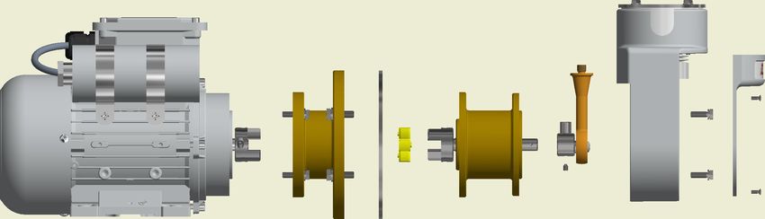
P2.x, P2.8x

1 Introduction

1.1 Intended use
Sample gas pumps are intended for installation in gas analysis systems for industrial applications.
The sample gas pump is only intended to convey gaseous media. It is not suitable for liquids.
Please note the additional information in chapters "Product Description" and "Operation and Control" along with the informa-
tion on specific intended use, existing material combinations, as well as pressure and temperature limits in the data sheets.

      DANGER          Potentially explosive atmosphere
                      Explosion hazard if used in hazardous areas.
                      The device is not suitable for operation in hazardous areas with potentially explosive at-
                      mospheres.
                      Do not expose the device to combustible or explosive gas mixtures.

When installed outdoors, ensure adequate protection from the weather, see chapter Requirements for the set-up location [>
page 8]

2    Bühler Technologies GmbH                                                                                      BE420001 ◦ 06/2021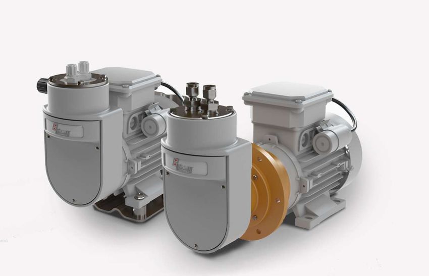
P2.x, P2.8x

1.2 Product key
The device is delivered with different configurations. The part number given on the type plate informs you about the specific
configuration of your device.
On the type plate you will find the order number as well as the 13-digit product key. This number is a code where each digit (x)
describes a certain feature:

 42   xx    x    x      x   x   x   9   0    00 Product characteristic
                                                 Base model
      56                                         P2.3 400 L/h (direct operation without intermediate flange)
      57                                         P2.4 400 L/h (with intermediate flange)
      63                                         P2.83 800 L/h (direct operation without intermediate flange)
      64                                         P2.84 800 L/h (with intermediate flange)
                                                 Motor voltage
            1                                    230 V 50/60 Hz; 1,09/1,17 A
            2                                    115 V 50/60 Hz; 2,78/2,3 A
            5                                    400 V 50/60 Hz; 0,5/0,46 A
                                                 Pump head position
                 1                               Normal position vertical
                 2                               turned by 180° *
                                                 Pump head material
                        1                        PTFE
                        2                        Stainless steel 1.4571
                        3                        PTFE with bypass valve *
                        4                        Stainless steel 1.4571 with bypass valve *
                                                 Valve material
                            1                    up to 100 °C; PTFE / PVDF **
                            2                    up to 160 °C; PTFE / PEEK
                                                 Screw-in connections (for 230 V and 400 V voltage)
                                                             PTFE Pump body                     Stainless steel pump body
                                9                           DN 4/6 (Standard)                        6 mm (Standard)
                                1                                 DN 6/8                                  8 mm
                                2                                 3/8"-1/4"                                3/8"
                                3                                 1/4"-1/8"
                                4                                 1/4"-1/6"                                 1/4"
                                                 Screw-in connections (for 115 V voltage)
                                                             PTFE Pump body                     Stainless steel pump body
                                9                          1/4"-1/6" (Standard)                       1/4" (Standard)
                                1                                 DN 6/8                                  8 mm
                                2                                 3/8"-1/4"                                3/8"
                                3                                 1/4"-1/8"
                                5                                 DN 4/6                                  6 mm
                                                 Mounting accessories
                                    9            incl. mounting bracket and bumper *
* not on P2.4 & P2.84
** for on P2.4, P2.83 & P2.84
If there are special instructions for a pump type, they are marked in the manual.
Take care of the limits of the pump. When ordering spare parts chose for the type matching part numbers (e.g. valves).

BE420001 ◦ 06/2021                                                                                    Bühler Technologies GmbH     3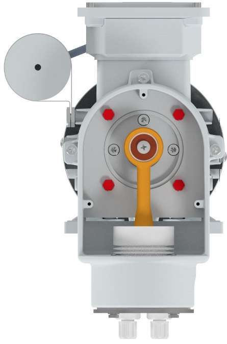
P2.x, P2.8x

1.3 Scope of delivery
P2.3, P2.83                                                      P2.4, P2.84
1 x Sample gas pump with motor                                  1 x Pump body with intermediate flange
4 x Rubber-metal bumpers                                        1 x Motor
1 x Mounting bracket                                            1 x Coupling flange
Product documentation                                           1 x Coupling
                                                                1 x Mounting ring
                                                                Product Documentation

1.4 Product description
The sample gas pumps are only intended to convey gaseous media. They are not suitable for liquids.
Please note the specifications in the appendix to this manual on the specific intended use, existing material combinations, as
well as pressure- and temperature limits. In addition, please also not the specifications and markings on the nameplates.
The pump head and the drive motor on the P2.4/P2.84 sample gas pump are isolated for use in hot applications. The sample gas
pump has a split adapter which can be mounted with one half inside a heated cabinet while the other half mounted on the out-
side supports the drive motor. In doing so, wall thicknesses of up to 30 mm can be bridged without additional modifications.
Applications where sample gas is still moist, can result in condensation in the lines and the pump body. In these cases the pump
head must be suspended (see item Alteration of hanging pump bodies [> page 10]).

4    Bühler Technologies GmbH                                                                                  BE420001 ◦ 06/2021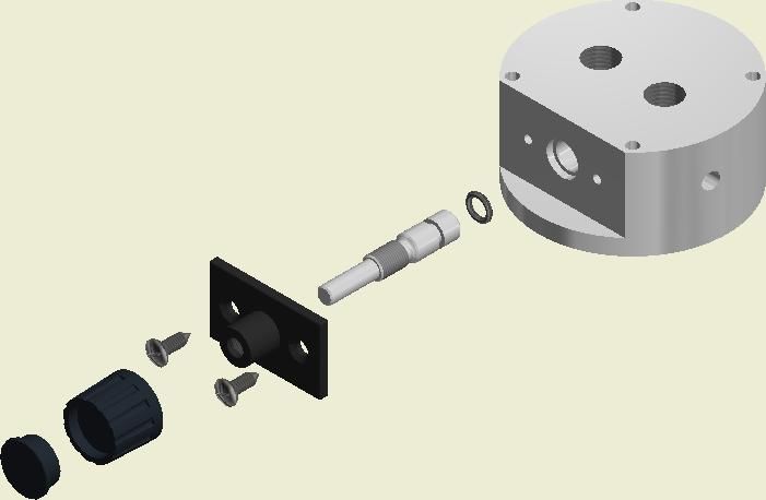
P2.x, P2.8x

2 Safety instructions

2.1 Important advice
Operation of the device is only valid if:
– the product is used under the conditions described in the installation- and operation instruction, the intended application
  according to the type plate and the intended use. In case of unauthorized modifications done by the user Bühler Technolo-
  gies GmbH can not be held responsible for any damage,
– when complying with the specifications and markings on the nameplates.
– the performance limits given in the datasheets and in the installation- and operation instruction are obeyed,
– monitoring devices and safety devices are installed properly,
– service and repair is carried out by Bühler Technologies GmbH,
– only original spare parts are used.
This manual is part of the equipment. The manufacturer keeps the right to modify specifications without advanced notice. Keep
this manual for later use.

Signal words for warnings
                     Signal word for an imminent danger with high risk, resulting in severe injuries or death if not avoided.
     DANGER

                     Signal word for a hazardous situation with medium risk, possibly resulting in severe injuries or death if not
    WARNING
                     avoided.

                     Signal word for a hazardous situation with low risk, resulting in damaged to the device or the property or
    CAUTION
                     minor or medium injuries if not avoided.

                     Signal word for important information to the product.
     NOTICE

Warning signs
In this manual, the following warning signs are used:

          Warning against hazardous situations                          General notice

          Warning against electrical voltage                            Disconnect from mains

          Warning against respiration of toxic gases                    Wear respirator

          Warning against acid and corrosive substances                 Wear eye/face protection

          Warning against potentially explosive atmospheres             Wear protection gloves

          Warning against hot surface

2.2 General indication of risk
The equipment must be installed by a professional familiar with the safety requirements and risks.
Be sure to observe the safety regulations and generally applicable rules of technology relevant for the installation site. Prevent
malfunctions and avoid personal injuries and property damage.

BE420001 ◦ 06/2021                                                                                     Bühler Technologies GmbH      5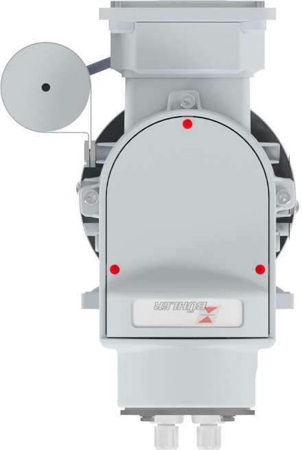
P2.x, P2.8x

The operator of the system must ensure:
– Safety notices and operating instructions are available and observed,
– The respective national accident prevention regulations are observed,
– The permissible data and operational conditions are maintained,
– Safety guards are used and mandatory maintenance is performed,
– Legal regulations are observed during disposal,
– compliance with national installation regulations.

Maintenance, Repair
Please note during maintenance and repairs:
– Repairs to the unit must be performed by Bühler authorised personnel.
– Only perform conversion-, maintenance or installation work described in these operating and installation instructions.
– Always use genuine spare parts.
– Do not install damaged or defective spare part. If necessary, visually inspect prior to installation to determine any obvious
  damage to the spare parts.
Always observe the applicable safety and operating regulations in the respective country of use when performing any type of
maintenance.

      DANGER          Electrical voltage
                      Electrocution hazard.
                      a) Disconnect the device from power supply.
                      b) Make sure that the equipment cannot be reconnected to mains unintentionally.
                      c) The device must be opened by trained staff only.
                      d) Regard correct mains voltage.

      DANGER          Toxic, corrosive gases
                      The measuring gas led through the equipment can be hazardous when breathing or
                      touching it.
                      a) Check tightness of the measuring system before putting it into operation.
                      b) Take care that harmful gases are exhausted to a save place.
                      c) Before maintenance turn off the gas supply and make sure that it cannot be turned
                         on unintentionally.
                      d) Protect yourself during maintenance against toxic / corrosive gases. Use suitable pro-
                         tective equipment.

      DANGER          Potentially explosive atmosphere
                      Explosion hazard if used in hazardous areas.
                      The device is not suitable for operation in hazardous areas with potentially explosive at-
                      mospheres.
                      Do not expose the device to combustible or explosive gas mixtures.

      CAUTION         Tilting risk
                      Damage of the device
                      Secure the device against any sudden translocation during maintenance.

      CAUTION         Hot surface
                      Burning hazard
                      According to the product type and operation conditions, the temperature of the housing
                      may exceed 50 °C during operation.
                      Depending on the conditions at the installation site it may be necessary to provide these
                      areas with appropriate warning signs.

6    Bühler Technologies GmbH                                                                                      BE420001 ◦ 06/2021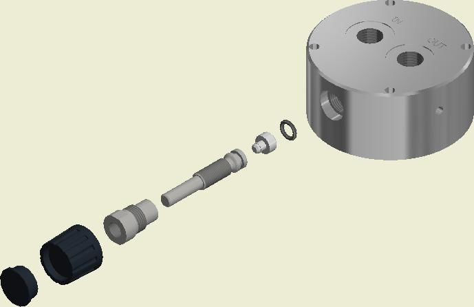
P2.x, P2.8x

3 Transport and storage
Only transport the product inside the original packaging or a suitable alternative.
The equipment must be protected from moisture and heat when not in use. They must be stored in a covered, dry and dust-free
room at a temperature between -20 °C to +40 °C (-4 °F to 104 °F). To avoid bearing damage, ensure a vibration-free environment
(v eff
P2.x, P2.8x

4 Installation and connection
Check the equipment for damage before installation. Among other things, this could be a damaged housing, supply cables, etc..
Never use equipment with obvious damage.

4.1 Requirements for the set-up location
      CAUTION         Equipment damage
                      Protect the equipment, particularly gas connections and gas lines, from dust, falling ob-
                      jects, as well as external blows.
                      Lightning
                      On principle, the operator must meet all applicable standards with respect to preventing
                      damage to the equipment due to lightning, which could result in equipment damage.

Never block the vent, and the exhaust air – including from adjacent units – must not be immediately suctioned in.
When installing without Bühler mounting bracket, be sure the motor is far enough from the back panel (at least 40 mm).
The sample gas pumps are rated for altitudes
P2.x, P2.8x
4.2 Mounting
CAUTION Damage to the device
Protect the device, especially the gas inlets and tubes, against dust, falling parts and ex-
ternal impact.
P2.3/P2.83
When installing the P2.3/P2.83 on mounting plates, use the included mounting bracket and only the included rubber/metal
bumpers. Operation without rubber/metal bumpers is prohibited. These must also be used when installing the pump on an ex-
isting substructure. For the hole pattern in the mounting bracket and the motor foot, please refer to the Technical Data at the
end of the operating and installation instructions.
P2.4/P2.84
Please refer to assembly drawing 42/025-Z02-02-2 when installing the P2.4/P2.84 sample gas pump. Before beginning the in-
stallation, verify the sample gas pump is complete. You will also require 6 x suitable length M6 bolts and nuts for installation.
The pump head on all pump types can only be aligned turned by 0° or 180°.
4.3 Special condition moist sample gas
Applications where the sample gas is still moist may result in condensate forming in line and the pump body. In these events
the pump head must be suspended (pump body facing down).
If the pump was not ordered this way, it can easily be converted on site.
Install the line between the gas output and condensate drain with a grade so the condensate can drain and does not collect in-
side the pump or the lines.
BE420001 ◦ 06/2021 Bühler Technologies GmbH 9P2.x, P2.8x
4.3.1 Alteration of hanging pump bodies
CAUTION Damage to the device
Especially with pump head pointing down, make sure that no dust or small parts can in-
trude the pump through the ventilations slot. Nevertheless, the slot must not be covered
directly. If this is not possible, the pump must not be mounted with pump head pointing
downward.
Please refer to assembly drawing 42/025-Z02-01-2 in the appendix for the conversion.
– Remove the three cross-tip screws (9) and remove the console cover (8) from the pump console (5). This exposes the crank
gear (10) and the Motor flange or, depending on pump model, the intermediate flange.
– The Pump console attaches to the flange with four hexagon screws (7) and lock washers (6). Completely unscrew these, hold-
ing the pump console, and rotate it 180° on the centring of the flange.
– Reinstall all parts in the reverse order. Please note the torque of the hexagon screws (7) is 3 Nm.
Installing the pump head offset by 45° or 90° is prohibited!
4.4 Connecting the sample gas line
The pumps are delivered with customized gas connections. Please compare the part-no. on the type plate with the part-no. ex-
plained in chapter "Introduction".
Avoid mixed installations, that is connecting metal tubes to plastic bodies. If this is unavoidable for sporadic applications, screw
the metal fitting with utmost care and without any use of force to the PTFE pump body.
Install the tubes in a way that the line at the inlet and outlet is flexible over a sufficient distance (pump vibrates).
The pumps are marked with “In” for inlet (input) and “Out” for outlet (output). Make sure that the connections to the tubes are
tight.
10 Bühler Technologies GmbH BE420001 ◦ 06/2021P2.x, P2.8x
4.5 Electrical connections
WARNING Hazardous electrical voltage
The device must be installed by trained staff only.
CAUTION Wrong mains voltage
Wrong mains voltage may damage the device.
Regard the correct mains voltage as given on the type plate.
A switch or circuit breaker (according to IEC 60947-1 and IEC 60947-3) must be installed for the sample gas pump. It must be easy
for the operator to reach. The switch must be marked as a cut-off for the device. It mustn't be integrated into a supply cable or
interrupt the earth conductor. It must further separate all poles of the sample gas pump from live parts.
The sample gas pump must be protected against prohibited heating with suitable overload protection (protective motor
switch).
Please note the rated current for the protective switch settings (see motor type plate).
Verify the pump motor has the correct voltage and frequency: Voltage tolerance ±5 %, frequency tolerance ±1 % - from rated
value.
Properly connect the sample gas pump per the respective wiring diagram (see below). If the wiring diagram inside the cover of
the terminal box is different, observe that instead. The required tightening torque for the nuts on the terminal board is 1.5 Nm.
Ensure the connecting cable has adequate cable relief. The clamping area of the cable gland is 6-10 mm. The required tightening
torque for the cable gland is 5 Nm.
The supply line and earthing cross-sections must be aligned with the rated current. Use a minimum line cross-section of
1.5 mm2.
Be sure to connect the following protective earth terminals to your on-site earth conductor per local regulations:
– Protective earth terminal inside the motor terminal box.
– Protective earth terminal on the outside of the motor housing.
– Protective earth terminal on the mounting bracket. (The earth bolt on the mounting bracket may alternatively be connected
to the protective earth connection on the outside of the motor housing via cable bridge.)
Stray electric currents may not flow through this connection.
No foreign objects, contaminants or moisture may be inside the junction box. Any unused cable gland openings must be sealed
with plugs approved for the application (if necessary Atex, IECEx).
To maintain the IP rating specified by the manufacturer, when sealing the terminal box with the cover ensure the original seal is
correctly seated and appropriately tighten the bolts.
Be sure to observe any varying information in the rating plate. The conditions at the site must correspond with all rating plate
information.
Three-phase motors Three-phase motors AC motors
Delta connection star connection with
lower voltage higher voltage operating capacitor
BE420001 ◦ 06/2021 Bühler Technologies GmbH 11P2.x, P2.8x
5 Operation and control
NOTICE
The device must not be operated beyond its specifications.
CAUTION Hot surface
Burning hazard
According to the product type and operation conditions, the temperature of the housing
may exceed 50 °C during operation.
Depending on the conditions at the installation site it may be necessary to provide these
areas with appropriate warning signs.
DANGER Toxic, corrosive gases
The measuring gas led through the equipment can be hazardous when breathing or
touching it.
a) Check tightness of the measuring system before putting it into operation.
b) Take care that harmful gases are exhausted to a save place.
c) Before maintenance turn off the gas supply and make sure that it cannot be turned
on unintentionally.
d) Protect yourself during maintenance against toxic / corrosive gases. Use suitable pro-
tective equipment.
5.1 Switching on the sample gas pump
Before switching on the device, ensure that:
– the hose and electrical connections are undamaged and correctly installed,
– no parts of the sample gas pump have been dismantled (e.g. cover),
– the gas inlet and outlet of the sample gas pump is not shut,
– the preliminary pressure is under 0.5 bar,
– in the event of throttling under 150 l/h (P2.x) or under 400 l/h (P2.8x) in continuous operation, a bypass is available,
– the ambient parameters are complied with,
– information on rating plates is observed,
– the voltage and frequency of the motor correspond to those of the network,
– the electrical connections are tightly fastened and the monitoring devices have been connected and configured correctly!
– air inlet openings and cooling surfaces are clean,
– protective measures have been carried out; earthing!
– the motor is secured correctly,
– the terminal box cover is closed and the cable entry points have been properly sealed,
– the elastomer sprocket of the coupling (only P2.4 / P2.84) is correctly installed and undamaged.
When switching the sample gas pump on make sure that
– no abnormal sounds or vibrations occur.
– the flow rate is neither too low nor too high. This would indicate a cracked bellow.
12 Bühler Technologies GmbH BE420001 ◦ 06/2021P2.x, P2.8x
5.2 Operating the sample gas pump
The sample gas pump is intended exclusively for the pumping of gaseous media. It is not suitable for liquids.
The sample gas pump should be operated without pre-compression. A preliminary pressure of more than 0.5 bar is not permit-
ted. The gas outlet must not be shut. The flow rate must be at least 50 l/h for the P2.x and at least 200 l/h for the P2.8x pumps. In
the event of throttling under 150 l/h for the P2.x or under 400 l/h for the P2.8x pumps in continuous operation, the flow rate
must be regulated via a bypass. In this case you should choose a version with bypass valve.
NOTICE
Extreme throttling reduces the life time of the bellow.
The output can be adjusted on pumps with built-in bypass valve. Do not apply a lot of force when turning the valve as the valve
could otherwise be damaged! The rotation range of the valve is about 7 rotations.
BE420001 ◦ 06/2021 Bühler Technologies GmbH 13P2.x, P2.8x
6 Maintenance
The unit must be cool before performing maintenance.
During maintenance, remember:
– The equipment must be maintained by a professional familiar with the safety requirements and risks.
– Only perform maintenance work described in these operating and installation instructions.
– When performing maintenance of any type, observe the respective safety and operation regulations.
NOTICE
Please refer to the assembly drawings in the appendix when carrying out maintenance.
DANGER Electrical voltage
Electrocution hazard.
a) Disconnect the device from power supply.
b) Make sure that the equipment cannot be reconnected to mains unintentionally.
c) The device must be opened by trained staff only.
d) Regard correct mains voltage.
DANGER Toxic, corrosive gases
The measuring gas led through the equipment can be hazardous when breathing or
touching it.
a) Check tightness of the measuring system before putting it into operation.
b) Take care that harmful gases are exhausted to a save place.
c) Before maintenance turn off the gas supply and make sure that it cannot be turned
on unintentionally.
d) Protect yourself during maintenance against toxic / corrosive gases. Use suitable pro-
tective equipment.
CAUTION Tilting risk
Damage of the device
Secure the device against any sudden translocation during maintenance.
CAUTION Gas leakage
The sample gas pump should not be dismantled under pressure.
CAUTION Hot surface
Burning hazard
According to the product type and operation conditions, the temperature of the housing
may exceed 50 °C during operation.
Depending on the conditions at the installation site it may be necessary to provide these
areas with appropriate warning signs.
Depending on the quality of the sample gas being transported, you may need to occasionally replace the inlet and outlet valves.
Instructions for replacing parts can be found in chapter Replacing the inlet and outlet valves [> page 15].
If the valves are very dirty, particularly after just a short time of operation, you should install a particle filter upstream from the
pump. This will significantly increase the operating life.
After approx. 500 operating hours tighten the screws for the mounting ring to 3 Nm.
14 Bühler Technologies GmbH BE420001 ◦ 06/2021P2.x, P2.8x
6.1 Replacing the inlet and outlet valves
Please refer to assembly drawing 42/025-Z02-01-2 in the appendix for this maintenance
– Remove the screw-in connections (18) from the pump body (13).
– Unscrew the valves (17) with a wide slot screwdriver. Stainless steel pump bodies have so-called displacers (20) under the
valves. These reduce the dead volume and must remain installed on these pump bodies.
– Screw the new valves into the pump body and tighten to max. 1 Nm. Be sure the valve is installed the correct direction. Valves
for a permitted gas inlet temperature of max. 100 °C are black/red, and grey/orange for max. 160 °C. Here the red or orange
end corresponds to the gas inlet and the black or grey end the gas outlet. The valves at the gas inlet are marked "EIN" and "IN"
and "AUS" and "OUT" at the gas outlet. The marking you see looking into the pump body from above determines the valve
function.
– Lastly, reinstall the screw-in connections in the pump body. In the case of stainless steel screw-in connections, replace any
damaged seals (19).
– Check the sample gas pump for leaks.
– Perform a test run. At a minimum, the following values must be reached:
Overpressure: P2.3/P2.4 = 1.7 bar; P2.83/P2.84 = 3.5 bar
Negative pressure: P2.3/P2.4 = -0.65 bar; P2.83/P2.84 = -0.75 bar
Flow rate: P2.3/P2.4 = 400 L/h; P2.83/P2.84 = 800 L/h
Record the maintenance including test values in the „operating log (template)" of the sample gas pump.
6.2 Replacing bellow and connecting rod-eccentric-combination
NOTICE Restrictions for connecting rod-eccentric replacement
The individual replacement of the eccentric, connecting rod or bearings is not allowed.
Only the factory pre-assembled connecting rod-eccentric combination is suitable for re-
placement by the operator.
Please refer to assembly drawing 42/025-Z02-01-2 in the appendix for this maintenance.
1. Remove the three cross-tip screws (9) and remove the console cover (8) from the pump console (5)
2. Clean any dust and other dirt off the sample gas pump. Wipe off stubborn dirt with a damp, clean cloth (do not use cleaning
products containing solvents).
Be sure to observe all notes in chapter Cleaning.
3. Remove the 4 hexagon screws (16) and the spring washers (15) at the top of the pump body (13). PTFE pump bodies also have
a mounting ring (14) installed for improved seating stress.
4. Carefully pull the pump body up and out of the pump console. Be careful not to overstretch the bellow (12). If the pump body
is stuck to the bellow, try carefully turning it to release it.
5. Hold the bellow just above the follower (10) and unscrew it anti-clockwise. When only changing the bellow, skip to step 14.
6. Remove the 4 hexagon screws (7) and lock washers (6) and remove the pump console from the flange.
7. Loosen and remove the set screw (11) from the eccentric of the crank gear (10). This may either be hexagon socket (SW 2) or
star drive (TX 8). Use the proper tool.
8. Now carefully remove the crank gear from the shaft. This is best done with 2 large slot screwdrivers.
9. Clean the shaft and if necessary remove any residue such as frictional corrosion, etc.
Check the fit size of 11k6.
10. Dampen the shaft with resin-free oil prior to assembly.
11. Attach the new crank gear to the shaft and align the locking bore for the set screw with the corresponding bore in the shaft.
Avoid using striking tools, as these may damage the ball bearings.
12. Insert the set screw with medium-strength threadlock and tighten to 1.5 Nm. Be sure the flat point of the set screw is prop-
erly seated in the bore on the shaft.
13. Now place the pump console over the crank gear again and either align it upward or rotated by 180° and secure with the
hexagon screws (7) and lock washers (6) - tightening torque 3 Nm.
14. Check the sealing surface and the pleats of the bellow for damage and dirt.
15. Insert the bellow through the pump console from above and twist it clockwise onto the plunger of the crank gear hand
tight.
16. Clean the pump body and check the sealing face for damage.
BE420001 ◦ 06/2021 Bühler Technologies GmbH 15P2.x, P2.8x
17. Attach the pump body to the bellow and turn into the desired position in relation to the gas inlet and outlet. On principle
the alignment of the pump body is irrelevant.
However, it’s important to ensure the marking on the mounting ring or pump body matches the installed valve and its
function. There is no difference between inlet valve and outlet valve. Their installation position determines the function.
The valves are always labelled "EIN" or "IN" for inlet and "AUS" or "OUT" for outlet.
18. Reattach the pump body with the 4 hexagon screws (16) and spring washers (15) and in the case of PTFE bodies with the
mounting ring, and tighten the bolts crosswise, first at 1 Nm, then 3 Nm.
19. Lastly, reattach the console cover with the 3 cross-tip screws.
20. Check the sample gas pump for leaks.
21. Perform a test run. At a minimum, the following values must be reached:
Overpressure: P2.3/P2.4 = 1.7 bar; P2.83/P2.84 = 3.5 bar
Negative pressure: P2.3/P2.4 = -0.65 bar; P2.83/P2.84 = -0.75 bar
Flow rate: P2.3/P2.4 = 400 L/h; P2.83/P2.84 = 800 L/h
Record the maintenance including test values in the „operating log (template)" of the sample gas pump.
6.3 Replacement of the O-ring of the bypass valve (optional)
Please refer to assembly drawing 42/025-Z02-01-2 in the appendix for this maintenance.
– Loosen the two bolts (24) and carefully pull the entire unit, consisting of valve plate (23), spindle (22) and O-ring (21) on the
knob (26) out of the pump body (13). On VA pump bodies, unscrew the spindle holder (25) with a SW13 open-end spanner,
turning clockwise, and remove the entire unit.
– Remove the old O-ring from the spindle.
– Moisten a new O-ring with suitable O-ring grease (e.g. Fluoronox S90/2) and carefully attach it to the spindle.
– Carefully reinsert the entire unit into the pump body, turning, and tighten the bolts or spindle holder.
– Check the sample gas pump for leaks.
6.4 Changing the Coupling
Please refer to assembly drawing 42/025-Z02-02-2 in the appendix for this maintenance.
If the coupling breaks, always investigate the cause! If caused by e.g. a frozen bearing, replace the entire head.
– Remove the pump head and motor with coupling flange.
– Remove the coupling flange from the motor.
– After removing the set screw, remove the coupling parts from the shafts and attach a new coupling.
– Screw the coupling flange back onto the motor and install the pump the same as during initial installation.
16 Bühler Technologies GmbH BE420001 ◦ 06/2021P2.x, P2.8x 7 Service and repair This chapter contains information on troubleshooting and correction should an error occur during operation. Repairs to the unit must be performed by Bühler authorised personnel. Please contact our Service Department with any questions: Tel.: +49-(0)2102-498955 or your agent If the equipment is not functioning properly after correcting any malfunctions and switching on the power, it must be inspected by the manufacturer. Please send the equipment inside suitable packaging to: Bühler Technologies GmbH - Reparatur/Service - Harkortstraße 29 40880 Ratingen Germany Please also attach the completed and signed RMA decontamination statement to the packaging. We will otherwise be unable to process your repair order. You will find the form in the appendix of these instructions, or simply request it by e-mail: service@buehler-technologies.com. BE420001 ◦ 06/2021 Bühler Technologies GmbH 17
P2.x, P2.8x

7.1 Troubleshooting and fault rectification
       CAUTION         Risk due to defective device
                       Personal injury or damage to property
                       a) Switch off the device and disconnect it from the mains.
                       b) Repair the fault immediately. The device should not be turned on again before elim-
                          ination of the failure.

       CAUTION         Hot surface
                       Burning hazard
                       According to the product type and operation conditions, the temperature of the housing
                       may exceed 50 °C during operation.
                       Depending on the conditions at the installation site it may be necessary to provide these
                       areas with appropriate warning signs.

Malfunction                      Cause                                         Action
Pump doesn’t start up            – Broken or incorrectly connected lead        – Check connection or fuse and switch
                                 – Defective motor                             – Replace motor
Pump doesn’t convey              – Defective or dirty valves                   – Carefully blow out or replace valves or see
                                                                                 chapter Replacing inlet and outlet valves.
                                 – Bypass valve open                           – Close bypass valve
                                 – Defective bypass valve O-ring               – have repaired by a Bühler service technician or
                                                                                 see Replacing the bypass valve O-ring
                                 – Torn bellow                                 – have repaired by Bühler service technician or
                                                                                 see Replacing the bellows and cam follower-ec-
                                                                                 centric combination.
                                 – Broken/worn ring gear                       – have repaired by a Bühler service technician or
                                                                                 "Replacing the coupling".
Noisy pump operation             – Crankshaft out of alignment                 – have repaired by Bühler service technician or
                                                                                 see Replacing the bellows and cam follower-ec-
                                                                                 centric combination.
                                 – Work ring gear                              – have repaired by a Bühler service technician or
                                                                                 "Replacing the coupling".
                                 – Loose coupling hub                          – have repaired by a Bühler service technician or
                                                                                 tighten the stud on the coupling hub to 1.34
                                                                                 Nm
                                 – Engine bracket damaged                      – Replace motor
Premature ring gear wear         – e.g. contact with ozone influences or sim- – Eliminate any physical changes to the ring gear
                                   ilar, causing a physical change to the ring
                                   gear
Protective device is triggering – Coil- and terminal short circuit             – Measure insulation resistance
                                 – Start-up time exceeded                      – Check start-up requirements
Poor performance                 – Leakage                                     – Tighten head screws, note torque (see chapter
                                                                                 "Maintenance").
                                 – Torn bellow                                 – have repaired by Bühler service technician or
                                                                                 see Replacing the bellows and cam follower-ec-
                                                                                 centric combination.
                                 – Defective or dirty valves                   – Carefully blow out or replace valves or see
                                                                                 chapter Replacing inlet and outlet valves.
Tab. 1: Troubleshooting

18    Bühler Technologies GmbH                                                                                     BE420001 ◦ 06/2021
P2.x, P2.8x
7.2 Spare parts and accessories
Please also specify the model and serial number when ordering parts.
Upgrade and expansion parts can be found in our catalog.
Available spare parts:
Spare part Item no. Position in assembly drawings
42/025-Z02-01-2 & 42/025-Z02-02-2
P2.3 / P2.4 Bellow 4200015 12a
Plunger / eccentric combination 4200075 10a, 11
Coupling ring gear 4220011 28c
Set of 100 °C valves 4201002 2x 17a
Set of 160 °C valves 4202002 2x 17b
Bypass O-ring 9009115 21a
P2.83 / P2.84 Bellow 4200071 12b
Plunger / eccentric combination 4200034 10c, 11
Coupling ring gear 4220011 28c
Set of 160 °C valves 4202002 2x 17b
Bypass O-ring 9009115 21a
Tab. 2: Spare Parts and Accessories
BE420001 ◦ 06/2021 Bühler Technologies GmbH 19P2.x, P2.8x 8 Disposal Dispose of parts so as not to endanger the health or environment. Follow the laws in the country of use for disposing of elec- tronic components and devices during disposal. 20 Bühler Technologies GmbH BE420001 ◦ 06/2021
P2.x, P2.8x

9 Appendices

9.1 General specifications for all pumps
General Specifications
Nominal voltage:                                        see ordering information
Protection class:                                       electric IP55
                                                        mechanical IP20
Dead volume:                                            8.5 ml
Materials of parts in contact with                      PTFE / PVDF (standard pump with 100 °C valves)
mediums by pump type:                                   + PEEK (standard pump with 160 °C valves)
                                                        + Viton (standard pump with 100 °C valves and bypass valve)
                                                        + PCTFE, Viton (standard pump with 160 °C valves and bypass valve)
                                                        + 1.4571 (VA pump body)
                                                        + 1.4401, Viton (VA pipe fitting)
                                                        + Viton (VA pump body with bypass valve)

9.2 Feed Curves
                             P2.3, P2.3C, P2.4, P2.4C                                                            P2.83, P2.84

                    Vacuum      Atm. pressure           Excess pressure                        Vacuum   Atm. pressure    Excess pressure

                                                                                                                        Feed curve
                                                Feed curve
 Flow rate

                                                                                   Flow rate

                              At 60 Hz +10% flow rate
                                                                                                          At 60 Hz +10% flow rate

9.3 Technical data for P2.3 and P2.83
P2.3/P2.83 Technical Data
Weight:                                                 approx. 6.5 kg
FM C-US (115 V only)
FM approval no.:                                        3038101/3038101C
Ambient temperature:                                    max. 60 °C
Medium temperature:                                     PTFE/PVDF valves max. 100 °C
                                                        PTFE/PEEK valves max. 160 °C

9.4 Technical data for P2.4 and P2.84
P2.4/P2.84 Technical Data
Weight:                                                 approx. 7 kg
FM C-US (115 V only)
FM approval no.:                                        3038101/3038101C
Ambient temperature
Motor:                                                  max. 60 °C
Pump head:                                              max. 100 °C
Medium temperature:                                     PTFE/PEEK valves max. 160 °C

BE420001 ◦ 06/2021                                                                                                         Bühler Technologies GmbH   21
P2.x, P2.8x
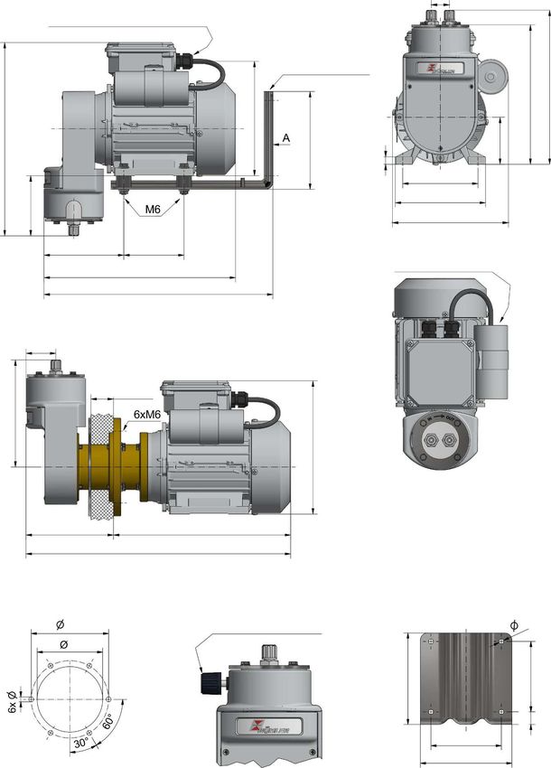
9.5 Dimensions
24
M16x1.5 cable fitting
Clamping range 6-10 mm
View with
pump head Mounting bracket
rotated
205
185
152
257
130
63
10
100
120
80
140 (230 V) / 154 (115 V)
111
106 80 Three-phase motors
255 without capacitor
304
40
Intermediate flange
max. 30
142
177
116 236
352
Cabinet cut-out for pumps with
intermediate flange
Adjustable bypass valve View A
110 (optional) 7
94
100
130
7
18
100
130
Installation notices:
1) This pump should be installed horizontally
2) If necessary, rotate the pump head during installation. When conveying gasses with condensate content it
must be installed valves down.
22 Bühler Technologies GmbH BE420001 ◦ 06/2021P2.x, P2.8x 10 Attached documents – Drawings: 42/025-Z02-01-2, 42/025-Z02-02-2; 42/025-Z02-03-2 – Declaration of conformity: KX 42 0001 – RMA - Decontamination Statement BE420001 ◦ 06/2021 Bühler Technologies GmbH 23
8 7 6 5 4 3 2 1
d
F hea F
ump
p
TFE
e -P 18b
valv
ss
ypa
B
21a/21b
19
22a/22b
24 23
20
26
E 27 18a E
d
hea
p
pum
1 17a/17b
.457
1
lve- 13g/13h
a 22d
ssv 21a/21b 16
pa
By 22c
25 15
13e/13f
D 26 D
27 14
1a...1n
13c/13d
Die Pumpentypen P2.4, P2.84, P2.4C, P2.4 Atex/Amex, P2.74 Atex und P2.84 Amex
13a/13b sind mit einem Zwischenflansch zwischen Motor und Pumpe ausgestattet. Beachten Sie
hierzu zus tzlich die spezifische Explosions- und Montagezeichnung 42/025-Z02-02-2.
The pump types P2.4, P2.84, P2.4C, P2.4 Atex/Amex, P2.74 Atex and P2.84 Amex
are equipped with an intermediate flange between the motor and the pump. Please also
note the specific exploded view and assembly drawing 42/025-Z02-02-2.
C C
12a/12b
5
6
B 7 B
Die Legende zu den Positionsnummerierungen dieser Zeichnung,
8b sowie deren spezifische Zuordnung zu den unterschiedlichen
Pumpentypen befindet sich auf der Zeichnung 42/025-Z02-03-2.
3 The legend for the item numbers in this drawing
11 and their specific assignment to the different pump
types can be found on drawing 42/025-Z02-03-2.
Alle Kanten Ma e ohne Ma stab: 1:1,75 Masse:
Alle Rechte Toleranzangabe
2 8a gratfrei vorbehalten nach ISO 2768-mK Werkstoff:
10a/10b/10c Datum: Name: Benennung:
Roh
= Bearb. 03.02.2021 Sundergeld Montagezeichnung - Assembly drawing -
A Gepr. P2.3, P2.83, P2.4, P2.84, P2.3C, P2.4C, A
4 X P2.2 Atex / Amex, P2.4 Atex / Amex, P2.72 Atex,
= Rz 63
P2.74 Atex, P2.82 Amex, P2.84 Amex
9
Y
= Rz 16 B HLER ZeichnungsNr.: 42/025-Z02-01-2A
Technologies GmbH
Z
a Motor Nr. 15.06.21 Sun 40880 Ratingen Art.Nr.: ---
= Rz 4 Zust. nd. Datum Name Ers.f r: Arbeitsanweisung:
8 7 6 5 4 3 2 18 7 6 5 4 3 2 1
X
F F
1a...1n Pumpenkopf / pump head
Max. Wandst rke 30mm
max. wall thickness 30mm
8a/8b
29
32 30
28
31
28b
28c 28a
E E
9
11
6
10a/10b/10c 7
33 6x Durchgangsbohrung 7
D 6x Through hole 7 D
Montagehinweise: 34
- Wandausschnitt nach Zeichnung herstellen (max. Wandst rke 30mm)
- Verbindungsschrauben (31/32) l sen und die Einheit Alle Details zu den pumpenspezifischen Bauteilen k nnen der
"Pumpenkopf-Zwischenflansch" (28/28a/28c/X) vom Kupplungsflansch (29) trennen/abziehen Explosions- und Montagezeichnung 42/025-Z02-01-2 entnommen werden
- Montage der Einheit "Motor-Kupplungsflansch" (1a-g/28b/29) von Au en (z.B. an einen Schaltschrank)
und Montagering (30) von Innen (z.B. innerhalb eines Schaltschranks) mit passenden Schrauben All details about the pump-specific components can be
und Muttern (M6) found in the Exploded and assembly drawing 42/025-Z02-01-2
- Die Einheit "Pumpenkopf-Zwischenflansch" auf das Gegenst ck (28b) schieben und wieder mit den
Verbindungsschrauben (31/32) montieren - an dieser Stelle kann der Pumpenkopf auch um 180 gedreht
montiert werden - der Pumpenkopf zeigt dann nach unten
- Die zus tzliche Befestigung des Motors mit z.B. der B hler Montagekonsole ist bei Pumpen mit
C Zwischenflansch weder notwendig noch zul ssig. Dies k nnte sich aufgrund einer System berbestimmung C
negativ auf die Kugellager auswirken.
Wichtiger Hinweis zur Kupplung bei Atex/Amex Pumpentypen:
Die Kupplungsnaben 28a und 28b werden mit einer Klemmschraube auf den jeweiligen
Wellen montiert. Diese Klemmschraube wird mit einem Schraubensicherungskleber und einem Wandausschnitt / mounting cut-out
speziellen Drehmoment montiert und d rfen nur durch einen B hler Servicetechniker gel st werden.
Bei dem Ersatzteil "Zwischenflanschbaugruppe (28/28a)" ist die Kupplungsnabe bereits vormontiert und 110
kann demnach auch betreiber-seitig ausgetauscht werden. 94
Assembly instructions:
- Create a wall cut-out according to the drawing (max. wall thickness 30mm)
B - Loosen the connecting screws (31/32) and remove the unit Die Legende zu den Positionsnummerierungen dieser Zeichnung, B
"pump head-intermediate flange" (28/28a/28c/X) from the coupling flange (29) sowie deren spezifische Zuordnung zu den unterschiedlichen
7
- Assemble the unit "Motor-coupling flange" (1a-g/28b/29) from the outside (e.g. to a cabinet) and Pumpentypen befindet sich auf der Zeichnung 42/025-Z02-03-2.
the mounting ring (30) from the inside (e.g. inside a cabinet) with suitable screws and nuts (M6)
6x
- The unit "pump head-intermediate flange" slide onto the counterpart (28b) The legend for the item numbers in this drawing
and re-assembled with the connecting screws (31/32) - at this point the pump head can also be rotated and their specific assignment to the different pump
60
by 180 installed - the pump head then points downwards types can be found on drawing 42/025-Z02-03-2.
- The additional fastening of the motor with e.g. the B hler mounting bracket at pumps with Intermediate
flange is neither necessary nor allowed. This could be due to system over-determination and have a negative Masse:
Alle Kanten Ma e ohne Ma stab: 1:1,75
effect on the ball bearings. 30 Alle Rechte Toleranzangabe
gratfrei vorbehalten nach ISO 2768-mK Werkstoff:
Important note for the coupling at Atex/Amex pump types: Roh
Datum: Name:
Benennung:
The coupling hubs 28a and 28b are mounted onto the shafts using clamping screws. = Bearb. 04.02.2021 Sundergeld
Montagezeichnung - Assembly drawing -
Gepr.
A This clamping screws are mounted with a screw lock adhesive and a special torque and shall only be released X P2.4, P2.84, P2.4C, P2.4 Atex/Amex, A
= Rz 63
P2.74 Atex, P2.84 Amex
by a B hler service technician. In case of the "intermediate flange assembly" (28/28a) as a replacement part,
the coupling hub is already pre-assembled and can therefore also be exchanged by the operator. Y
= Rz 16 B HLER ZeichnungsNr.: 42/025-Z02-02-2A
Technologies GmbH
Z
a Motor Nr. 15.06.21 Sun 40880 Ratingen Art.Nr.: ---
= Rz 4 Zust. nd. Datum Name Ers.f r: Arbeitsanweisung:
8 7 6 5 4 3 2 1Legende und spezifische Zuordnung der Positionsnummern aus den Montagezeichnungen
Zeichnungsnummer/Drawing no. 42/025-Z02-03-2 | Rev.A | Date: 15.06.2021 | Autor: Sundergeld Legend and specific assignment for the item numbers of the assembly drawings
42/025-Z02-01-2 & 42/025-Z02-02-2
Pos. No. Description Beschreibung P2.3 P2.83 P2.4 P2.84 P2.3C P2.4C P2.2 Atex P2.2 Amex P2.4 Atex P2.4 Amex P2.72 Atex P2.74 Atex P2.82 Amex P2.84 Amex
1a Motor 230V 50/60Hz Motor 230V 50/60Hz X X X X X X --- --- --- --- --- --- --- ---
1b Motor 115V 50/60Hz Motor 115V 50/60Hz X X X X X X --- --- --- --- --- --- --- ---
1c Motor 230/400V 50/60Hz Motor 230/400V 50/60Hz X X X X X X --- --- --- --- --- --- --- ---
1d Motor 230V 50/60Hz Atex, IECEx Motor 230V 50/60Hz Atex, IECEx --- --- --- --- --- --- X --- X --- X X --- ---
1e Motor 115V 50/60Hz Atex, IECEx Motor 115V 50/60Hz Atex, IECEx --- --- --- --- --- --- X --- X --- X X --- ---
1f Motor 380-420V 50Hz Atex, IECEx Motor 380-420V 50Hz Atex, IECEx --- --- --- --- --- --- X --- X --- X X --- ---
1g Motor 500V 50Hz Atex, IECEx Motor 500V 50Hz Atex, IECEx --- --- --- --- --- --- X --- X --- X X --- ---
1h Motor 230V 50/60Hz Cl.I, Div.2 Motor 230V 50/60Hz Cl.I, Div.2 --- --- --- --- --- --- --- X --- X --- --- X X
1i Motor 115V 50/60Hz Cl.I, Div.2 Motor 115V 50/60Hz Cl.I, Div.2 --- --- --- --- --- --- --- X --- X --- --- X X
2 Montagekonsole Mounting bracket X X --- --- X --- X X --- --- X --- X ---
3 Gummi-Metall-Puffer Shock absorber X X --- --- X --- X X --- --- X --- X ---
4 Mutter DIN 6923 - M6 Nut DIN 6923 - M6 X X --- --- X --- X X --- --- X --- X ---
5 Pumpenkonsole Pump housing X X X X X X X X X X X X X X
6 Federring DIN 127 B5,1 Spring washer DIN 127 B5,1 X X X X X X X X X X X X X X
7 Schraube DIN 933 M5x16 Screw DIN 933 M5x16 X X X X X X X X X X X X X X
8a Konsolendeckel - standard Cover - standard X X X X --- --- X X X X X X X X
8b Konsolendeckel mit Schlitzen Cover with slots --- --- --- --- X X --- --- --- --- --- --- --- ---
9 Schraube DIN 966 M3x8 Screw DIN 966 M3x8 X X X X X X X X X X X X X X
10a Kurbeltrieb für 400l/h Pumpen (Stößel gold) Crank drive for 400l/h pumps (plunger gold) X --- X --- X X X X X X --- --- --- ---
10b Kurbeltrieb für 700l/h Pumpen (Stößel grün) Crank drive for 700l/h pumps (plunger green) --- --- --- --- --- --- --- --- --- --- X X --- ---
10c Kurbeltrieb für 800l/h Pumpen (Stößel schwarz) Crank drive for 800l/h pumps (plunger black) --- X --- X --- --- --- --- --- --- --- --- X X
11 Schraube DIN 915 M4x6 oder ISO 4028 M4X6 TX 8 Screw DIN 915 M4x6 or ISO 4028 M4X6 TX 8 X X X X X X X X X X X X X X
12a Faltenbalg für 400l/h Pumpen (4 Falten) Below for 400l/h pumps (4 folds) X --- X --- X X X X X X --- --- --- ---
12b Faltenbalg für 700l/h und 800l/h Pumpen (8 Falten) Below for 700l/h and 800l/h pumps (8 folds) --- X --- X --- --- --- --- --- --- X X X X
13a Pumpenkörper - PTFE für 400l/h Pumpen Pump head - PTFE for 400l/h pumps X --- X --- X X X X X X --- --- --- ---
13b Pumpenkörper - PTFE für 800l/h Pumpen Pump head - PTFE for 800l/h pumps --- X --- X --- --- --- --- --- --- --- --- X X
13c Pumpenkörper - PTFE mit Bypassventil für 400l/h Pumpen Pump head - PTFE with bypass valve for 400l/h pumps X --- X --- X X X X X X --- --- --- ---
13d Pumpenkörper - PTFE mit Bypassventil 800l/h Pumpen Pump head - PTFE with bypass valve for 800l/h pumps --- X --- X --- --- --- --- --- --- --- --- X X
13e Pumpenkörper - 1.4571 für 400l/h und 700l/h Pumpen Pump head - 1.4571 for 400l/h and 700l/h pumps X --- X --- X X X X X X X X --- ---
13f Pumpenkörper - 1.4571 für 800l/h Pumpen Pump head - 1.4571 for 800l/h pumps --- X --- X --- --- --- --- --- --- --- --- X X
13g Pumpenkörper - 1.4571 mit Bypassventil für 400l/h und 700l/h Pumpen Pump head - 1.4571 with bypass valve for 400l/h and 700l/h pumps X --- X --- X X X X X X X X --- ---
13h Pumpenkörper - 1.4571 mit Bypassventil für 800l/h Pumpen Pump head - 1.4571 with bypass valve for 800l/h pumps --- X --- X --- --- --- --- --- --- --- --- X X
14 Montagering - nur für PTFE Pumpenkörper Mounting ring - only for pump heads made of PTFE X X X X X X X X X X --- --- X X
15 Spannscheibe DIN 6796 d=4 Clamping washer DIN 6796 d=4 X X X X X X X X X X X X X X
16 Schraube DIN 933 M4x45 Screw DIN 933 M4x45 X X X X X X X X X X X X X X
17a Ventil - geeignet bis zu 100°C Gaseingangstemperatur Valve - suitable up to 100°C gas inlet temperature X --- --- --- X --- X X --- --- --- --- --- ---
17b Ventil - geeignet bis zu 160°C Gaseingangstemperatur Valve - suitable up to 160°C gas inlet temperature X X X X X X X X X X X X X X
18a Kunststoff Einschraubverschraubung - diverse Typen - siehe Pumpendatenblätter Plastic fitting - various types - see pump data sheets X X X X X X X X X X --- --- X X
18b Edelstahl Rohrverschraubung - diverse Typen - siehe Pumpendatenblätter Stainless steel fitting - various types - see pump data sheets X X X X X X X X X X X X X X
19 Dichtring - nur für Edelstahl Pumpenkörper Sealing ring - only for pump heads made of 1.4571 X X X X X X X X X X X X X X
20 Verdränger - nur für Edelstahl Pumpenkörper Displacer - only for pump heads made of 1.4571 X X X X X X X X X X X X X X
21a O-Ring - FKM O-Ring made of FKM X X X X X X X X X X X X X X
21b O-Ring - FFKM O-Ring made of FFKM X X X X X X X X X X X X X X
22a Spindel für Bypassventil - geeignet bis zu 100°C Gaseingangstemperatur Spindle for PTFE bypass valve - suitable up to 100°C gas inlet temperature X --- --- --- X --- X X --- --- --- --- --- ---
22b Spindel für Bypassventil - geeignet bis zu 160°C Gaseingangstemperatur Spindle for PTFE bypass valve - suitable up to 160°C gas inlet temperature --- X X X --- X --- --- X X X X X X
22c Spindel für Edelstahl Bypassventil Spindle for 1.4571 bypass valve X X X X X X X X X X X X X X
22d Spindelspitze Spindle tip X X X X X X X X X X X X X X
23 Montageplatte Bypassventil Mounting plate bypass valve X X X X X X X X X X --- --- X X
24 Schraube DIN 7982 4,2x13 Screw DIN 7982 4,2x13 X X X X X X X X X X --- --- X X
25 Spindelaufnahme Spindle holder X X X X X X X X X X X X X X
26 Drehknopf Knob X X X X X X X X X X X X X X
27 Deckel Cover X X X X X X X X X X X X X X
28 Zwischenflansch Intermediate flange --- --- X X --- X --- --- X X --- X --- X
28a/28b Kupplungsnabe Coupling hub --- --- X X --- X --- --- X X --- X --- X
28c Kupplungsstern Spider --- --- X X --- X --- --- X X --- X --- X
29 Kupplungsflansch Coupling flange --- --- X X --- X --- --- X X --- X --- X
30 Montagering Mounting ring --- --- X X --- X --- --- X X --- X --- X
31 Schraube DIN 933 M6x20 Screw DIN 933 M6x20 --- --- X X --- X --- --- X X --- X --- X
32 Unterlegscheibe DIN 125 A6,4 Washer DIN 125 A6,4 --- --- X X --- X --- --- X X --- X --- X
33 Unterlegscheibe DIN 125 A5,3 Washer DIN 125 A5,3 --- --- X X --- X --- --- X X --- X --- X
34 Schraube DIN 933 M5x20 Screw DIN 933 M5x20 --- --- X X --- X --- --- X X --- X --- X
X Kompletter Pumpenkopf - diverse Kombinationsmöglichkeiten Complete pump head - various combinations X X X X X X X X X X X X X XYou can also read