SI5391 REFERENCE MANUAL - ULTRA LOW JITTER, ANY-FREQUENCY, ANY OUTPUT CLOCK GENERATOR: SI5391 REFERENCE MANUAL - SILICON LABS
←
→
Page content transcription
If your browser does not render page correctly, please read the page content below

Si5391 Reference Manual

Ultra Low Jitter, Any-Frequency, Any Output Clock Generator:
Si5391 Reference Manual                                                                              RELATED DOCUMENTS

The Si5391 Clock Generators combine MultiSynth™ technologies to enable any-fre-                       • Si5391 Data Sheet
quency clock generation for applications that require the highest level of jitter perform-            • Si5391 Device Errata
ance. These devices are programmable via a serial interface with in-circuit programma-                • Si5391-EVB User Guide
ble nonvolatile memory (NVM) ensuring power up with a known frequency configura-
                                                                                                      • Si5391-EVB Schematics, BOM & Layout
tion.
                                                                                                      • IBIS models

               Skyworks Solutions, Inc. • Phone [781] 376-3000 • Fax [781] 376-3100 • sales@skyworksinc.com • www.skyworksinc.com
1      Rev. 0.5 • Skyworks Proprietary Information • Products and Product Information are Subject to Change Without Notice • January 11, 2022   1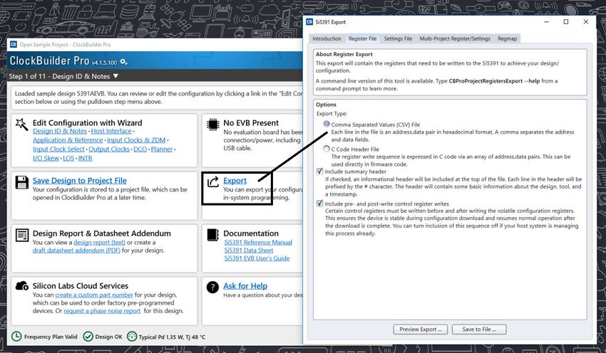
Table of Contents
1. Work Flow Using ClockBuilder Pro and the Register Map. . . . . . . . . . . . . . . 5
    1.1 Field Programming            .   .   .   .   .   .   .   .   .   .   .   .   .   .   .   .   .   .   .   .   .   .   .   .   .   .   .   . 5

2. Family Product Comparison. . . . . . . . . . . . . . . . . . . . . . . . . . 6
    2.1 Grade P (Precision) Restrictions and Requirements                        .   .   .   .   .   .   .   .   .   .   .   .   .   .   .   .   . 6
    2.2 Si5391P Grade Frequency Plan Rules                   .   .   .   .   .   .   .   .   .   .   .   .   .   .   .   .   .   .   .   .   .   .   6
      2.2.1 Output Clock Domains . . . .                     .   .   .   .   .   .   .   .   .   .   .   .   .   .   .   .   .   .   .   .   .   .   6
      2.2.2 Output Clock Locations. . . .                    .   .   .   .   .   .   .   .   .   .   .   .   .   .   .   .   .   .   .   .   .   .   6
      2.2.3 Output Clock Format Restrictions                 .   .   .   .   .   .   .   .   .   .   .   .   .   .   .   .   .   .   .   .   .   .   7

3. Functional Description. . . . . . . . . . . . . . . . . . . . . . . . . . . . 8
    3.1 Dividers .       .   .   .   .   .   .   .   .   .   .   .   .   .   .   .   .   .   .   .   .   .   .   .   .   .   .   .   .   .   .   . 9

4. Power-up, Reset, and Initialization . . . . . . . . . . . . . . . . . . . . . .                                                               10
5. Dynamic PLL Changes. . . . . . . . . . . . . . . . . . . . . . . . . . . .11
    5.1 Dynamic Changes to Output Frequencies without Changing PLL Settings .                                    .   .   .   .   .   .   .   .   .11
    5.2 Dynamic Changes to Output Frequencies while Changing PLL Settings Using a CBPro Register
        Map . . . . . . . . . . . . . . . . . . . . . . . . . . . . . . . .                                                                      .12

6. NVM Programming . . . . . . . . . . . . . . . . . . . . . . . . . . . .                                                                       13
7. Clock Inputs. . . . . . . . . . . . . . . . . . . . . . . . . . . . . . .                                                                     15
    7.1 Reference Input Selection (IN0, IN1, IN2, XA/XB) .                       .   .   .   .   .   .   .   .   .   .   .   .   .   .   .   .   .16
    7.2 Types of Inputs . . . . . . . . . .                          .   .   .   .   .   .   .   .   .   .   .   .   .   .   .   .   .   .   .   .17
      7.2.1 Crystal on XA/XB. . . . . . . .                          .   .   .   .   .   .   .   .   .   .   .   .   .   .   .   .   .   .   .   .17
      7.2.2 Clock Input on XA/XB . . . . . .                         .   .   .   .   .   .   .   .   .   .   .   .   .   .   .   .   .   .   .   .18
      7.2.3 Clock Inputs on IN2, IN1, IN0 . . .                      .   .   .   .   .   .   .   .   .   .   .   .   .   .   .   .   .   .   .   .19
      7.2.4 Unused Inputs. . . . . . . . .                           .   .   .   .   .   .   .   .   .   .   .   .   .   .   .   .   .   .   .   .20
      7.2.5 Input Clock Rise Time Considerations .                   .   .   .   .   .   .   .   .   .   .   .   .   .   .   .   .   .   .   .   .20
    7.3 Fault Monitoring . . .               .   .   .   .   .   .   .   .   .   .   .   .   .   .   .   .   .   .   .   .   .   .   .   .   .   .21
      7.3.1 Status Indicators . .            .   .   .   .   .   .   .   .   .   .   .   .   .   .   .   .   .   .   .   .   .   .   .   .   .   .22
      7.3.2 Interrupt Pin (INTR) .           .   .   .   .   .   .   .   .   .   .   .   .   .   .   .   .   .   .   .   .   .   .   .   .   .   .23

8. Outputs . . . . . . . . . . . . . . . . . . . . . . . . . . . . . . . .                                                                       25
    8.1 Output Crosspoint Switch .               .   .   .   .   .   .   .   .   .   .   .   .   .   .   .   .   .   .   .   .   .   .   .   .   .25
    8.2 Output Divider (R) Synchronization .                 .   .   .   .   .   .   .   .   .   .   .   .   .   .   .   .   .   .   .   .   .   .26
    8.3 Performance Guidelines for Outputs .                 .   .   .   .   .   .   .   .   .   .   .   .   .   .   .   .   .   .   .   .   .   .27
    8.4 Output Signal Format . . . . . . . . . . . . . . . .                                         .   .   .   .   .   .   .   .   .   .   .   .28
      8.4.1 Differential Output Terminations . . . . . . . . . . .                                   .   .   .   .   .   .   .   .   .   .   .   .29
      8.4.2 Differential Output Swing Modes . . . . . . . . . .                                      .   .   .   .   .   .   .   .   .   .   .   .30
      8.4.3 Programmable Common Mode Voltage for Differential Outputs                                .   .   .   .   .   .   .   .   .   .   .   .31
      8.4.4 LVCMOS Output Terminations . . . . . . . . . . .                                         .   .   .   .   .   .   .   .   .   .   .   .31
      8.4.5 LVCMOS Output Impedance and Drive Strength Selection . .                                 .   .   .   .   .   .   .   .   .   .   .   .31
      8.4.6 LVCMOS Output Signal Swing . . . . . . . . . . .                                         .   .   .   .   .   .   .   .   .   .   .   .32
      8.4.7 LVCMOS Output Polarity . . . . . . . . . . . . .                                         .   .   .   .   .   .   .   .   .   .   .   .33

              Skyworks Solutions, Inc. • Phone [781] 376-3000 • Fax [781] 376-3100 • sales@skyworksinc.com • www.skyworksinc.com
2     Rev. 0.5 • Skyworks Proprietary Information • Products and Product Information are Subject to Change Without Notice • January 11, 2022         2
8.4.8 Output Driver Settings for LVPECL, LVDS, HCSL, and CML . . . . . . . . . . . . .34
8.4.9 Setting the Differential Output Driver to Non-Standard Amplitudes . . . . . . . . . . .35
8.5 Output Enable/Disable . . . . . . . . . . . . . . . . . . . . . . . . . . .37
8.5.1 Output Driver State When Disabled . . . . . . . . . . . . . . . . . . . . .38
8.5.2 Synchronous Output Enable/Disable Feature . . . . . . . . . . . . . . . . . .38
8.6 Output Buffer Supply Voltage Selection . . . . . . . . . . . . . . . . . . . . . .38
8.7 Output Delay Control . . . . . . . . . . . . . . . . . . . . . . . . . . . .39
9. Zero Delay Mode (All Si5391 Devices Except Si5391P) . . . . . . . . . . . . . . . 40
10. Digitally-Controlled Oscillator (DCO) Mode (All Si5391 Devices Except Si5391P) . . . . 41
10.1 Using the N Dividers for DCO Applications . . . . . . . . . . . . . . . . . . . .41
10.1.1 DCO with Frequency Increment/Decrement Pins/Bits . . . . . . . . . . . . . . .41
10.1.2 DCO with Direct Register Writes . . . . . . . . . . . . . . . . . . . . . .41
10.2 Using the M Divider for DCO Applications . . . . . . . . . . . . . . . . . . . .41
11. Serial Interface . . . . . . . . . . . . . . . . . . . . . . . . . . . . . 42
11.1 I2C Interface . . . . . . . . . . . . . . . . . . . . . . . . . . . . . .44
11.2 SPI Interface . . . . . . . . . . . . . . . . . . . . . . . . . . . . . .46
12. Crystal, XO and Device Circuit Layout Recommendations . . . . . . . . . . . . . 51
12.1 64-Pin QFN Si5391/Si5391P Layout Recommendations . . . . . . . . . . . . . . .51
12.1.1 Si5391 with an External Reference (Not Relevant to the Si5391P) . . . . . . . . . .51
12.1.2 Si5391/Si5391P Crystal Guidelines . . . . . . . . . . . . . . . . . . . . .52
12.1.3 Si5391/Si5391P Output Clocks . . . . . . . . . . . . . . . . . . . . . .58
13. Power Management . . . . . . . . . . . . . . . . . . . . . . . . . . . 60
13.1 Power Management Features . . . . . . . . . . . . . . . . . . . . . . . .60
13.2 Power Supply Recommendations . . . . . . . . . . . . . . . . . . . . . . .60
13.3 Power Supply Sequencing . . . . . . . . . . . . . . . . . . . . . . . . .61
13.4 Grounding Vias . . . . . . . . . . . . . . . . . . . . . . . . . . . . .61
14. Register Map . . . . . . . . . . . . . . . . . . . . . . . . . . . . . . 62
14.1 Base vs. Factory Preprogrammed Devices . . . . . . . . . . . . . . . . . . . .62
14.2 “Base” Devices (a.k.a. “Blank” Devices) . . . . . . . . . . . . . . . . . . . . .62
14.3 “Factory Preprogrammed” (Custom OPN) Devices . . . . . . . . . . . . . . . . .62
14.4 Register Map Overview and Default Settings Values . . . . . . . . . . . . . . . . .63
15. Si5391A/B Register Map . . . . . . . . . . . . . . . . . . . . . . . . . . 64
15.1 Page 0 Registers Si5391 . . . . . . . . . . . . . . . . . . . . . . . . . .64
15.2 Page 1 Registers Si5391 . . . . . . . . . . . . . . . . . . . . . . . . . .73
15.3 Page 2 Registers Si5391 . . . . . . . . . . . . . . . . . . . . . . . . . .78
15.4 Page 3 Registers Si5391 . . . . . . . . . . . . . . . . . . . . . . . . . .84
15.5 Page 9 Registers Si5391 . . . . . . . . . . . . . . . . . . . . . . . . . .87
15.6 Page A Registers Si5341 . . . . . . . . . . . . . . . . . . . . . . . . . .89
Skyworks Solutions, Inc. • Phone [781] 376-3000 • Fax [781] 376-3100 • sales@skyworksinc.com • www.skyworksinc.com
3 Rev. 0.5 • Skyworks Proprietary Information • Products and Product Information are Subject to Change Without Notice • January 11, 2022 315.7 Page B Registers Si5391 . . . . . . . . . . . . . . . . . . . . . . . . . .91
16. Revision History. . . . . . . . . . . . . . . . . . . . . . . . . . . . . 93
Skyworks Solutions, Inc. • Phone [781] 376-3000 • Fax [781] 376-3100 • sales@skyworksinc.com • www.skyworksinc.com
4 Rev. 0.5 • Skyworks Proprietary Information • Products and Product Information are Subject to Change Without Notice • January 11, 2022 4Si5391 Reference Manual • Work Flow Using ClockBuilder Pro and the Register Map
1. Work Flow Using ClockBuilder Pro and the Register Map
This reference manual is to be used to describe all the functions and features of the parts in the product family with register map details
on how to implement them. It is important to understand that the intent is for customers to use the ClockBuilder Pro to provide the initial
configuration for the device. Although the register map is documented, all the details of the algorithms to implement a valid frequency
plan are fairly complex and are beyond the scope of this document. Real-time changes to the frequency plan and other operating
settings are supported by the devices. However, describing all the possible changes is not a primary purpose of this document. Refer to
the applications notes within the ClockBuilder Pro GUI for information on how to implement the most common, real-time frequency plan
changes.
The primary purpose of the software is to enable use of the device without an in-depth understanding of its complexities. The software
abstracts the details from the user to allow focus on the high level input and output configuration, making it intuitive to understand and
configure for the end application. The software walks the user through each step, with explanations about each configuration step in the
process to explain the different options available. The software will restrict the user from entering an invalid combination of selections.
The final configuration settings can be saved, written to an EVB and a custom part number can be created for customers who prefer to
order a factory preprogrammed device. The final register maps can be exported to text files, and comparisons can be done by viewing
the settings in the register map described in this document.
1.1 Field Programming
To simplify design and software development of systems using the Si5391/Si5391P, a field programmer is available in addition to the
evaluation board. The ClockBuilder Pro Field Programmer supports both “in-system” programming (for devices already mounted on a
PCB), as well as “in-socket” programming of Si5391/Si5391P sample devices. Refer to https://www.skyworksinc.com/en/Products/Tim-
ing for information about this kit.
Skyworks Solutions, Inc. • Phone [781] 376-3000 • Fax [781] 376-3100 • sales@skyworksinc.com • www.skyworksinc.com
5 Rev. 0.5 • Skyworks Proprietary Information • Products and Product Information are Subject to Change Without Notice • January 11, 2022 5Si5391 Reference Manual • Family Product Comparison
2. Family Product Comparison
The following table is a comparison of the different parts in the product family showing the differences in the inputs, MultiSynths, outputs
and package type.
Table 2.1. Family Feature Comparison
Number of
Part Number Number of Inputs Number of Outputs Package Type
Fractional Dividers
Si5391 4 5 12 64-pin QFN
2.1 Grade P (Precision) Restrictions and Requirements
Some applications like 56G PAM4 SERDES require even higher performance than is already provided by standard clock generators.
The Si5391P (Precision) grade internally calibrates out linearity errors to deliver the world's best jitter performance for output clocks
of 156.25, 312.5, and 625 MHz frequencies. The grade 'P' part XTAL frequency is fixed at 48 MHz and variation must be within ±100
ppm across temperature, load capacitance mismatch and aging. The P (Precision) grade part has various restrictions compared to the
highly flexible A grade device. These restrictions are required to guarantee the 100-fs integrated jitter specification in the 12kHz-20MHz
frequency band for 156.25MHz, 312.5MHz, and 625MHz output frequencies.
This section identifies most of the restrictions/rules required to achieveSi5391 Reference Manual • Family Product Comparison
Table 2.2. Only Domain 1 and 2 Output Frequencies
Output Clock Frequencies Output Clock Location allowed?
0A 0 1 2 3 4 5 6 7 8 9 9A
125/156.25/312/625 yes yes yes yes yes yes yes no no no no no
25/125/200 no no no yes yes yes yes yes yes yes yes yes
50/100 no no no no yes yes yes yes yes yes yes yes
Table 2.3. Domain 1, 2, and 3 Output Frequencies
Output Clock Frequencies Output Clock Location allowed?
0A 0 1 2 3 4 5 6 7 8 9 9A
125/156.25/312/625 yes yes yes yes yes yes yes no no no no no
25/125/200 no no no yes yes yes yes yes yes yes yes yes
50/100 no no no no yes yes yes yes yes yes yes yes
322.265625/644.53125 no no no no no no no no yes yes yes yes
Table 2.4. Only Domain 1 and 3 Output Frequencies
Output Clock Frequencies Output Clock Location allowed?
0A 0 1 2 3 4 5 6 7 8 9 9A
156.25/312/625 yes yes yes yes no no no no no no no no
125 yes yes yes yes yes yes yes yes yes yes yes yes
322.265625/644.53125 no no no no no no no no yes yes yes yes
156.25MHz/312.5MHz/625MHz Separation Rules to Domain 2 and 3 Clocks:
Even though the Si5391P has minimal coupling between adjacent clocks, a domain 2 or 3 clock that is adjacent to 156.25/312.5/625
MHz may couple too much energy to allow these Domain 1 clocks to meetSi5391 Reference Manual • Functional Description
3. Functional Description
The Si5391 uses next generation MultiSynth™ technology to offer the industry’s most frequency-flexible, high performance clock
generator. The internal Phase-Locked Loop (PLL) locks to either an external crystal (XA/XB) or to an external input on XAXB, IN0,
IN1 or IN2. The input frequency (crystal or external input) is multiplied by the PLL and divided by the MultiSynth™ stage (N divider)
and R divider to any frequency in the range of 100 Hz to 712.5 MHz per output. The PLL is fully contained and does not require
external loop filter components to operate. Its function is to phase lock to the selected input and provide a common reference to all
the output MultiSynth highperformance fractional dividers (N dividers). The high-resolution fractional MultiSynth™ dividers enables true
any-frequency input to any-frequency output. A cross-point mux connects any of the MultiSynth divided frequencies to any of the output
drivers. Additional integer output dividers (R) provide further frequency division if required. The frequency configuration of the device is
programmed by setting the input dividers (P), the PLL feedback fractional divider (M_NUM/M_DEN), the MultiSynth fractional dividers
(N_NUM/ N_DEN), and the output integer dividers (R). Skyworks’ Clockbuilder Pro configuration utility determines the optimum divider
values for any desired input and output frequency plan.
The output drivers offer flexible output formats which are independently configurable on each of the outputs. This clock generator is
fully configurable via its serial interface (I2C/SPI) and includes in-circuit programmable non-volatile memory. The block diagram for the
Si5391 is shown in the figure below.
VDDA
VDD
3
IN_ SEL[1:0]
Si5391 Dividers/
Clock Drivers
Generator VDDO0
IN0
÷P0 OUT0
IN0b ÷R0 OUT0b
IN1 PLL OUT0A
IN1b
÷P1 ÷R0A OUT0Ab
PD
VDDO1
IN2
÷P2 LPF ÷R1
OUT1
IN2b OUT1b
Mn VDDO2
÷
Md OUT2
÷R2 OUT2b
VDDO3
OUT3
÷ PXAXB ÷R3 OUT3b
MultiSynth
XB VDDO4
N0n
25-54 MHz
OSC ÷ t0 OUT4
XTAL N0d ÷R4 OUT4b
XA
Si5391P: 48 MHz only N1n VDDO5
÷
N1d
t1 ÷R5 OUT5
Zero Delay OUT5b
Mode VDDO6
N2n
÷ t2 OUT6
FB_IN
N2d ÷R6 OUT6b
÷Pfb
FB_ INb VDDO7
N3n
÷ t3 OUT7
N3d ÷R7 OUT7b
N4n VDDO8
÷ t4 OUT8
N4d ÷R8 OUT8b
VDDO9
OUT9
÷R9 OUT9b
I2C_ SEL
SDA/ SDIO OUT9A
SPI / ÷R9A OUT9Ab
A1/ SDO NVM
SCLK
I2 C Status
Frequency
Control
A0/CSb Monitors
SYNCb
OEb
RSTb
LO Lb
FINC
FDEC
INTRb
Figure 3.1. Si5391 Block Diagram
Skyworks Solutions, Inc. • Phone [781] 376-3000 • Fax [781] 376-3100 • sales@skyworksinc.com • www.skyworksinc.com
8 Rev. 0.5 • Skyworks Proprietary Information • Products and Product Information are Subject to Change Without Notice • January 11, 2022 8Si5391 Reference Manual • Functional Description
3.1 Dividers
There are five main divider classes within the Si5391/Si5391P shown above in the Figure 3.1 Si5391 Block Diagram on page 8.
1. Wide range input dividers Pfb, P2, P1, P0
• Only integer divider values
• Range is from 1 to 216 – 1
• Since the input to the phase detector needs to be > 10 MHz, the practical range is limited to ~75 on the high side.
• Each divider has an update bit that must be written to cause a newly written divider value to take effect.
2. Narrow range input divider Pxaxb
• Only divides by 1, 2, 4, 8
3. Feedback M divider
• Ultra low jitter in fractional and integer modes
• MultiSynth divider
• Integer or fractional divide values
• 44 bit numerator, 32 bit denominator
• Practical range limited by phase detector range of 10–120 MHz and VCO range of 13500–14256 MHz
• This divider has an update bit that must be written to cause a newly written divider value to take effect.
4. Output N dividers
• Ultra low jitter in fractional and integer modes
• MultiSynth divider
• Integer or fractional divide values
• 44 bit numerator, 32 bit denominator
• Min value is 10
• Maximum value is 212 – 1
• Each N divider has an update bit that must be written to cause a newly written divider value to take effect. In addition there is a
global update bit that when written updates all N dividers.
5. Output R divider
• Only even integer divide values
• Min value is 2
• Maximum value is 225 – 2
Additionally, FSTEPW can be used to adjust the nominal output frequency in DCO mode. See Section 10. Digitally-Controlled Oscillator
(DCO) Mode (All Si5391 Devices Except Si5391P) for more information and block diagrams on DCO mode.
Skyworks Solutions, Inc. • Phone [781] 376-3000 • Fax [781] 376-3100 • sales@skyworksinc.com • www.skyworksinc.com
9 Rev. 0.5 • Skyworks Proprietary Information • Products and Product Information are Subject to Change Without Notice • January 11, 2022 9Si5391 Reference Manual • Power-up, Reset, and Initialization
4. Power-up, Reset, and Initialization
Once power is applied, the device begins an initialization period where it downloads default register values and configuration data
from NVM and performs other initialization tasks. Communicating with the device through the serial interface is possible once this
initialization period is complete. No clocks will be generated until the initialization is complete.
Hard Reset RST
Power-Up bit asserted pin asserted
NVM download
Soft Reset
bit asserted
Initialization
Serial interface
ready
Figure 4.1. Initialization from Power-up, Hard Reset, and Soft Reset
There are two types of commanded resets available.
1. The first is the hard reset. A hard reset is functionally similar to a device power-up. All registers will be restored to the values stored
in NVM, and all circuits will be restored to their initial state including the serial interface. A hard reset is initiated using the RST pin
or by asserting the hard reset register bit.
2. The second type of reset is a soft reset. Asserting the soft reset rgister bit bypasses the NVM download and simply re-starts the
internal initialization sequence.
NVM Download
NVM
2x RAM
OTP
Figure 4.2. Si5391/Si5391P Memory Configuration
Table 4.1. Reset Control Registers
Hex Address [Bit Field]
Register Name Function
Si5391
Performs the same function as power cycling the device. All registers will be
HARD_RST 001E[1]
restored to their default values.
Performs a soft reset. Resets the device while it does not re-download the
SOFT_RST 001C[0]
register configuration from NVM.
The Si5391/Si5391P is fully configurable using the serial interface (I2C or SPI). At power-up the device downloads its default register
values from internal non-volatile memory (NVM). Application specific default configurations can be pre-written into NVM allowing the
device to generate specific clock frequencies at power-up. Writing default values to NVM is in-circuit programmable with normal
operating power supply voltages applied to its VDD (1.8 V) and VDDA (3.3 V) pins. Neither VDDOx or VDDS supplies are required to
write the NVM.
Skyworks Solutions, Inc. • Phone [781] 376-3000 • Fax [781] 376-3100 • sales@skyworksinc.com • www.skyworksinc.com
10 Rev. 0.5 • Skyworks Proprietary Information • Products and Product Information are Subject to Change Without Notice • January 11, 2022 10Si5391 Reference Manual • Dynamic PLL Changes
5. Dynamic PLL Changes
It is possible for the PLL to become unresponsive (i.e., lose lock indefinitely) when it is dynamically reprogrammed or changed via the
serial port. Any change that causes the VCO frequency to change by more than 250 ppm since Power-up, a NVM download, assertion
of SOFT_RST, or changes to any of the following list of registers will require the special PLL re-initialization sequence below
Registers:
• XAXB_FREQ_OFFSET
• PXAXB
• MXAXB_NUM
• MXAXB_DEN
• M_NUM
• M_DEN
PLL Re-Initialization Sequence:
1. First, the preamble:
Write 0x0B24 = 0xC0
Write 0x0B25 = 0x00
2. Wait 300 ms for Grade A/B/C/D, Wait 625ms for Grade P
3. Then, perform the desired register modifications.
4. Write SOFT_RST - 0x001C[0] = 1
5. Write the post-amble:
Write 0x0B24 = 0xC3
Write 0x0B25 = 0x02
Note: This programming sequence applies only to Rev D and later revisions. The preamble and postamble values for updating certain
registers during device operation are different for earlier revisions. Either the new or old values below may be written to revision D or
later devices without issue. No system software changes are necessary for legacy systems. When writing old values, note that reading
back these registers will not give the written old values, but will reflect the new values. Skyworks recommends using the new values
for all revision D (described above) and later designs, since the write and read values will match. Please contact Skyworks if you need
information about an earlier revision. Please always ensure to use the correct sequence for the correct revision of the device. Also
check for the latest information online. This information is updated from time to time. The latest information is always posted online.
5.1 Dynamic Changes to Output Frequencies without Changing PLL Settings
This section applies to the following scenario:
1. A CBPro generated register map "was" used to program either the volatile or the non-volatile memory of a Si5391. Changes to
output frequencies without changing the PLL settings are desired.
2. The CBPro project file can be used to look for the VCO frequency (FVCO), Ry, Nx values for each OUTy in the design report
and/or the datasheet addendum.
OUTy = FVCO/(Nx * Ry)
Solve for Nx based on the desired OUTy. The Nx dividers can be digitally controlled to so that all outputs connected to the Nx divider
change frequency in real time without any transition glitches. There are two ways to control the Nx divider to accomplish this task:
1. Use the Frequency Increment/Decrement Pins or register bits.
2. Write directly to the numerator or denominator of the Nx divider.
The details of both methods are covered in 10.1 Using the N Dividers for DCO Applications.
Skyworks Solutions, Inc. • Phone [781] 376-3000 • Fax [781] 376-3100 • sales@skyworksinc.com • www.skyworksinc.com
11 Rev. 0.5 • Skyworks Proprietary Information • Products and Product Information are Subject to Change Without Notice • January 11, 2022 11Si5391 Reference Manual • Dynamic PLL Changes
5.2 Dynamic Changes to Output Frequencies while Changing PLL Settings Using a CBPro Register Map
This section applies to the following scenario:
1. A CBPro generated register map "is" used to program either the voltatile or the non-volatile memory of a Si5391.
2. This needs a register write sequence provided in the CBPro export section as shown below.
Figure 5.1. CBPro Register Write Sequence While Changing PLL Settings
Skyworks Solutions, Inc. • Phone [781] 376-3000 • Fax [781] 376-3100 • sales@skyworksinc.com • www.skyworksinc.com
12 Rev. 0.5 • Skyworks Proprietary Information • Products and Product Information are Subject to Change Without Notice • January 11, 2022 12Si5391 Reference Manual • NVM Programming
6. NVM Programming
Devices have two categories of non-volatile memory: user NVM and Factory (Skyworks) NVM. Each type is segmented into NVM
banks. There are three NVM banks, one of which is used for factory programming (whether a base part or an Orderable Part Number).
Two user NVM banks remain; therefore, the device NVM can be re-burned in the field up to two times. Factory NVM cannot be
modified, and contains fixed configuration information for the device.
The ACTIVE_NVM_BANK device setting can be used to determine which user NVM bank is currently being used and therefore how
many banks, if any, are available to burn. The following table describes possible values:
Table 6.1. NVM Bank Burning Values
Active NVM BANK Value (Deci- Number of User Banks Burned Number of User Banks Available to Burn
mal)
3 (factory state) 1 2
15 2 1
63 3 0
Note: While polling DEVICE_READY during the procedure below, the following conditions must be met to ensure the correct values are
written into the NVM:
• VDD and VDDA power must both be stable throughout the process.
• No additional registers may be written or read during DEVICE_READY polling. This includes the PAGE register at address 0x01.
DEVICE_READY is available on every register page, so no page change is needed to read it.
• Only the DEVICE_READY register (0xFE) should be read during this time.
The procedure for writing registers into NVM is as follows:
1. Write registers as needed for desired device operation. Verify device operation to ensure the device is configured correctly before
preceeding. Do not skip this important step.
2. You may write to the user scratch space (Registers 0x026B to 0x0272 DESIGN_ID0-DESIGN_ID7) to identify the contents of the
NVM bank.
3. Write 0xC7 to NVM_WRITE register. This starts the internal NVM burn sequence, writing NVM from the internal registers. Do not
access ANY other registers than DEVICE_READY during the NVM burn process. Doing so may corrupt the NVM burn in progress.
4. Poll DEVICE_READY until DEVICE_READY=0x0F (waiting for completion of NVM burn sequence).
5. Set NVM_READ_BANK 0x00E4[0]=1. This will download the NVM contents back into non-volatile memory (registers).
6. Poll DEVICE_READY until DEVICE_READY=0x0F (waiting for NVM download to complete).
7. Read ACTIVE_NVM_BANK and verify that the value is the next highest value in the table above. For example, from the factory it
will be a 3. After NVM_WRITE, the value will be 15.
Alternatively, steps 5 and 6 can be replaced with a Hard Reset, either by RSTb pin, HARD_RST register bit, or power cycling the device
to generate a POR. All of these actions will load the new NVM contents back into the device registers.
The ClockBuilder Pro Field Programmer kit is a USB attached device to program supported devices either in-system (wired to your
PCB) or in-socket (by purchasing the appropriate field programmer socket). ClockBuilder Pro software is then used to burn a device
configuration (project file). Learn more at https://www.skyworksinc.com/en/products/timing/evaluation-kits/general/clockbuilder-pro-field-
programmer.
Table 6.2. NVM Programming Registers
Register Name Hex Address Function
[Bit Field]
ACTIVE_NVM_BANK 0x00E2[7:0] Identifies the active NVM bank.
NVM_WRITE 0x00E3[7:0] Initiates an NVM write when written with value 0xC7.
NVM_READ_BANK 0x00E4[0] Download register values with content stored in NVM.
Skyworks Solutions, Inc. • Phone [781] 376-3000 • Fax [781] 376-3100 • sales@skyworksinc.com • www.skyworksinc.com
13 Rev. 0.5 • Skyworks Proprietary Information • Products and Product Information are Subject to Change Without Notice • January 11, 2022 13Si5391 Reference Manual • NVM Programming
Register Name Hex Address Function
[Bit Field]
DEVICE_READY 0x00FE[7:0] Indicates that the device is ready to accept commands when
value = 0x0F.
Warning: Any attempt to read or write any register other than DEVICE_READY before DEVICE_READY reads as 0x0F may corrupt
the NVM programming and may corrupt the register contents, as they are read from NVM. Note that this includes accesses to the
PAGE register.
Skyworks Solutions, Inc. • Phone [781] 376-3000 • Fax [781] 376-3100 • sales@skyworksinc.com • www.skyworksinc.com
14 Rev. 0.5 • Skyworks Proprietary Information • Products and Product Information are Subject to Change Without Notice • January 11, 2022 14Si5391 Reference Manual • Clock Inputs
7. Clock Inputs
Clock inputs can be used on all Si5391 grades except for Si5391P. The PLL in the Si5391 (not P grade) requires a clock input at the
XAXB pins or IN2, 1, 0 input pins or a clock from a crystal connected across the XAXB pins. The PLL of the Si5391P requires a 48 MHz
crystal, not input clock, connected at the XAXB pins and does not use the IN0, 1, 2 inputs.
VDDA
VDD
3
IN_ SEL[1:0]
Si5391 Dividers/
Clock Drivers
Generator VDDO0
IN0
÷P0 OUT0
IN0b ÷R0 OUT0b
IN1 PLL OUT0A
IN1b
÷P1 ÷R0A OUT0Ab
PD
VDDO1
IN2
÷P2 LPF ÷R1
OUT1
IN2b OUT1b
Mn VDDO2
÷
Md OUT2
÷R2 OUT2b
VDDO3
OUT3
÷ PXAXB ÷R3 OUT3b
MultiSynth
XB VDDO4
N
25-54 MHz
OSC ÷ 0n t0 OUT4
XTAL N0d ÷R4 OUT4b
XA
Si5391P: 48 MHz only N1n VDDO5
÷
N1d
t1 ÷R5 OUT5
Zero Delay OUT5b
Mode VDDO6
N2n
÷ t2 OUT6
FB_IN
N2d ÷R6 OUT6b
÷Pfb
FB_ INb VDDO7
N3n
÷ t3 OUT7
N3d ÷R7 OUT7b
N VDDO8
÷ 4n t4 OUT8
N4d ÷R8 OUT8b
VDDO9
OUT9
÷R9 OUT9b
I2C_ SEL
SDA/ SDIO OUT9A
SPI / ÷R9A OUT9Ab
A1/ SDO NVM
SCLK
I2 C Status
Frequency
Control
A0/CSb Monitors
SYNCb
OEb
RSTb
LO Lb
FINC
FDEC
INTRb
Figure 7.1. Clock Inputs Example
Skyworks Solutions, Inc. • Phone [781] 376-3000 • Fax [781] 376-3100 • sales@skyworksinc.com • www.skyworksinc.com
15 Rev. 0.5 • Skyworks Proprietary Information • Products and Product Information are Subject to Change Without Notice • January 11, 2022 15Si5391 Reference Manual • Clock Inputs
7.1 Reference Input Selection (IN0, IN1, IN2, XA/XB)
The active clock input is selected using the IN_SEL1,0 pins or by register control. The register bit IN_SEL_REGCTRL determines input
selection as pin or register selectable.
Note: If the selected input does not have a clock, all output clocks will be shut off (squelched) until a valid input clock is present.
Table 7.1. Manual Input Selection Using IN_SEL[1:0] Pins
IN_SEL[1:0] Selected Input
0 0 IN0
0 1 IN1
1 0 IN2
1 1 XA/XB
Table 7.2. Input Control Registers
Hex Address [Bit Field]
Register Name Function
Si5391
Note:
XAXB_FREQ_OFFSET1 0202[7:0]–0205[7:0] 1. Do NOT use this register on any version of the Si5391.
Selects between the XTAL or external reference clock on the
XAXB_EXTCLK_EN 090E[0] XA/XB pins. Default is 0, XTAL. Set to 1 to use an external ref-
erence oscillator. It must always be set to 0 (default) for Si5391P.
IN_SEL_REGCTRL 0021[0] Determines pin or register clock input selection.
IN_SEL 0021[2:1] Selects the input when in register input selection mode.
Allows enabling/disabling IN0, IN1, IN2 and FB_IN when not in
IN_EN 0949[3:0]
use.
Table 7.3. XAXB Pre-Scale Divide Ratio Register
Setting Name Hex Address [Bit Field] Function
Si5391/Si5391P
PXAXB 0x0206[1:0] Sets the XAXB input divider value according to the table below.
The following table lists the values, along with the corresponding divider ratio.
Table 7.4. XAXB Pre-Scale Divide Values
Value (Decimal) PXAXB Divider Value
0 1
1 2
2 4
3 8
Skyworks Solutions, Inc. • Phone [781] 376-3000 • Fax [781] 376-3100 • sales@skyworksinc.com • www.skyworksinc.com
16 Rev. 0.5 • Skyworks Proprietary Information • Products and Product Information are Subject to Change Without Notice • January 11, 2022 16Si5391 Reference Manual • Clock Inputs
7.2 Types of Inputs
7.2.1 Crystal on XA/XB
An external standard crystal (XTAL) is connected to XA/XB when this input is configured as a crystal oscillator. For all Si5391 devices,
except the Si5391P, a crystal frequency of 25 MHz can be used, although crystals in the frequency range of 48 MHz to 54 MHz are
highly recommended for the best jitter performance. All Si5391 devices, except Si5391P, include a built-in XTAL load capacitance (CL)
of 8 pF, but crystals with CL specifications as high as 18 pF can also be used. When using crystals with CL specs higher than 8 pf it
is not generally recommended to use external capacitors from XA/XB to ground to increase the crystal load capacitance. See Section
12. Crystal, XO and Device Circuit Layout Recommendations for the PCB layout guidelines.
For Si5391P devices, the crystal frequency MUST be 48 MHz and have a loading capacitance of 8 pf. No external loading capacitors
are needed since the device has a built-in loading capacitance of 8 pf.
Skyworks Solutions, Inc. • Phone [781] 376-3000 • Fax [781] 376-3100 • sales@skyworksinc.com • www.skyworksinc.com
17 Rev. 0.5 • Skyworks Proprietary Information • Products and Product Information are Subject to Change Without Notice • January 11, 2022 17Si5391 Reference Manual • Clock Inputs
7.2.2 Clock Input on XA/XB
The Si5391P must use a 48 MHz crystal on XAXB, not a clock.
An external clock can also be input on the XA/XB pins of all Si5391 devices except the Si5391P. Selection between the external crystal
or clock is controlled by register configuration. The device includes internal 8 pF crystal loading capacitors which eliminates the need
for external capacitors when using a crystal. The internal crystal load capacitors (CL) are disabled in external clock mode. Because
the input buffer at XA/XB is a lower noise buffer than the buffers on IN2,1,0, a very clean input clock at XA/XB, such as a very high
quality TCXO or XO, will, in some cases, produce lower output clock jitter than the same input at IN2,1,0. If the XAXB input is unused
and powered down then the XA and XB inputs can be left floating. Note that ClockBuilder Pro will power down the XAXB input if it is
selected as “unused”. If XAXB is powered up but no input is applied then the XA input should be left floating and the XB input must be
connected directly to ground. Both a single-ended or a differential clock can be connected to the XA/XB pins as shown in the following
figure:
Differential Connection Single-ended XO Connection
nc X1 nc X1
nc X2 nc X2
2xCL Note: 2.0 Vpp_se max 2xCL
0.1 µf 0.1 µf
50
XA XA
OSC OSC
XB
50
XO with Clipped Sine XB
0.1 µf
2xCL
Wave Output 2xCL
Si5391 Si5391
0.1 µf
Note: 2.5 Vpp diff max
Single-ended Connection Crystal Connection
nc X1
nc X2
Note: 2.0 Vpp_se max X1
2xCL 2xCL
CMOS/XO Output
XA
0.1 µf
R1 XA
XTA
OSC L OSC
XO VDD R1 R2 R2
XB
0.1 µf 0.1 µf
3.3 V 523 Ohms 422 Ohms XB
2.5 V 475 Ohms 649 Ohms 2xCL 2xCL Si5391
Si5391 X2
1.8 V 158 Ohms 866 Ohms
Figure 7.2. Crystal Resonator and External Reference Clock Connection Options
In addition to crystal operations, the Si5391 accepts a clipped sine wave, CMOS, or differential reference clock on the XA/XB interface.
Most clipped sine wave and CMOS TCXOs have insufficient drive strength to drive a 100 Ω or 50 Ω load. For this reason, place the
TCXO as close to the Si5391 as possible to minimize PCB trace length. In addition, ensure that both the Si5391 and the TCXO are both
connected directly to the ground plane. The above figure includes the recommended method of connecting a clipped sine wave TCXO
to the Si5391. Because the Si5391 provides DC bias at the XA and XB pins, the ~800 mV peak-peak swing can be input directly into
the XA interface of the Si5391 once it has been ac-coupled.
The above figure also illustrates the recommended method of connecting a CMOS rail-to-rail output to the XA/XB inputs of the
Si5391Because the signal is single-ended, the XB input is ac-coupled to ground. The resistor network attenuates the rail-to-rail output
swing to ensure that the maximum input voltage swing at the XA pin is less than the data sheet specification. The signal is ac-coupled
before connecting it to the Si5391 XA input. Again, since the signal is single-ended, the XB input should be ac-coupled to ground.
If an external oscillator is used as the XAXB reference, it is important to use a low jitter source because there is effectively no jitter
attenuation from the XAXB pins to the outputs. To minimize jitter at the XA/XB pins, the rise time of the XA/XB signals should be as fast
as possible.
Skyworks Solutions, Inc. • Phone [781] 376-3000 • Fax [781] 376-3100 • sales@skyworksinc.com • www.skyworksinc.com
18 Rev. 0.5 • Skyworks Proprietary Information • Products and Product Information are Subject to Change Without Notice • January 11, 2022 18Si5391 Reference Manual • Clock Inputs
For best jitter performance, use a XAXB frequency above 40 MHz. Also, for XAXB frequencies higher than 125 MHz, the PXAXB
control must be used to divide the input frequency down below 125 MHz.
In most applications, using the internal OSC with an external crystal provides the best phase noise performance. See AN905: External
References; Optimizing Performance for more information on the performance of various XO's with these devices.
The recommended crystal and oscillator suppliers are listed in the Si534x/8x Jitter Attenuators Recommended Crystal, TCXO and
OCXOs Reference Manual.
7.2.3 Clock Inputs on IN2, IN1, IN0
This section applies to all Si5391 devices except the Si5391P. The Si5391P cannot accept an input clock on IN0,1, 2.
A single ended or differential clock may be input to the IN2, 1, 0 inputs as shown below. All input signals must be ac-coupled. When
INx (x = 0, 1, 2) is unused and powered down the plus and minus input can be left floating. ClockBuilder Pro will power down any INx
input that is selected as “unused.” If any INx is powered up but does not have any input signal then the plus input should be left floating
and the minus input should be directly connected to ground. If the plus input is left floating and the minus input is connected to ground
with a 4.7 kΩ or smaller resistor, then the INx can be powered up or down when it does not have an input. The recommended input
termination schemes are shown in the figure below. Unused inputs can be disabled by register configuration.
Standard AC-Coupled Differential
0.1uF *
50 Clock IC
INx
Standard
100
INxb
50
LVDS, LVPECL, CML 0.1uF *
* These caps should have < ~5 ohms capacitive reactance at the clock input frequency.
Standard AC-Coupled Single-Ended
C1
RS R1 0.1uF
Clock IC
50
INx
Standard
3.3V, 2.5V, 1.8V LVCMOS R2
INxb
RS matches the CMOS driver to a 0.1uF
50 ohm transmission line (if used)
0.1uF *
**
*This cap should have less than ~20 ohms of capacitive reactance at the clock input
frequency.
** Only when 3.3V LVCMOS driver is present, use R2 = 845 ohm and R1 = 267 ohm if
needed to keep the signal at INx < 3.6 Vpp_se. Including C1 = 6 pf may improve the
output jitter due to faster input slew rate at INx. If attenuation is not needed for
InxSi5391 Reference Manual • Clock Inputs
7.2.4 Unused Inputs
Unused inputs can be disabled and left unconnected. Register 0x0949[3:0] defaults the input clocks to being enabled. Clearing the
unused input bits will disable them. Enabled inputs not actively being driven by a clock may benefit from pull up or pull down resistors to
avoid them responding to system noise.
7.2.5 Input Clock Rise Time Considerations
It is well known that slow rise time input clocks with low slew rates are a cause of increased jitter. If the slew rate is low enough, the
output jitter will increase. The following figure shows the effect of a low slew rate on RMS jitter for a differential clock input. It shows the
relative increase in the amount of RMS jitter due to slow rise time and is not intended to show absolute jitter values.
IN_X Slew Rate in Differential Mode
5
4.5
4
3.5
3
Relateive Jitter
2.5
2
1.5
JTYP 1
0.5
0
0 100 200 300 400 500 600
Input Slew (V/us)
Figure 7.4. Effect of Low Slew Rate on RMS Jitter
Skyworks Solutions, Inc. • Phone [781] 376-3000 • Fax [781] 376-3100 • sales@skyworksinc.com • www.skyworksinc.com
20 Rev. 0.5 • Skyworks Proprietary Information • Products and Product Information are Subject to Change Without Notice • January 11, 2022 20Si5391 Reference Manual • Clock Inputs
7.3 Fault Monitoring
The Si5391 provides fault indicators which monitor loss of signal (LOS) of the inputs (IN0, IN1, IN2, XA/XB, FB_IN) and loss of lock
(LOL) for the PLL, as shown in the diagram below. These fault conditions, as well as other internal status indications, are provided
through a combination of internal registers and externally provided signals (LOLb and INTRb). Usage and configuration of status/fault
monitoring features, as well as mapping these to the INTRb output, are described on following sub sections.
IN0 Si5391
÷P0 LOS0
IN0b
LOL
IN1
÷P1 LOS1
IN1b PLL
PD LPF
IN2
÷P2 LOS2
IN2b
Mn
÷
Md
LOSXAB
XA
OSC
XB
FB_IN
÷Pfb LOSFB
FB _INb
LOLb
INTRb
Figure 7.5. Fault Monitors
Skyworks Solutions, Inc. • Phone [781] 376-3000 • Fax [781] 376-3100 • sales@skyworksinc.com • www.skyworksinc.com
21 Rev. 0.5 • Skyworks Proprietary Information • Products and Product Information are Subject to Change Without Notice • January 11, 2022 21Si5391 Reference Manual • Clock Inputs
7.3.1 Status Indicators
The state of the status monitors are accessible by reading registers through the serial interface or with dedicated pin (LOLb). Each of
the status indicator register bits has a corresponding sticky bit (_FLG) in a separate register location. Once a status bit is asserted its
corresponding _FLG bit will remain asserted until cleared. Writing a logic zero to a _FLG register bit clears its state.
Table 7.5. Status Monitor Bits
Setting Name Hex Address [Bit Field] Function
Status Register Bits
SYSINCAL 0x000C[0] Asserted when in calibration.
Loss of Signal at the XA input.
LOSXAXB 0x000C[1]
The Xb input does not have an LOS detector.
LOSREF 0x000C[2] Loss of Signal for the input that has been selected.
LOL 0x000C[3] Loss of Lock for the PLL.
SMBUS_TIMEOUT 0x000C[5] The SMB bus has a timeout.
LOSIN[3:0] 0x000D[3:0] Loss of Signal for the FB_IN, IN2, IN1, IN0 inputs.
Sticky Status Register Bits
SYSINCAL_FLG 0x0011[0] Sticky bit for SYSINCAL
LOSXAXB_FLG 0x0011[1] Sticky bit for LOSXAXBB
LOSREF_FLG 0x0011[2] Sticky bit for LOSREF
LOL_FLG 0x0011[3] Sticky bit for LOL
SMBUS_TIMEOUT_FLG 0x0011[5] Sticky bit for SMBUS_TIMEOUT
LOSIN_FLG 0x0012[3:0] Sticky bit for FB_IN, IN2, IN1, IN0
Skyworks Solutions, Inc. • Phone [781] 376-3000 • Fax [781] 376-3100 • sales@skyworksinc.com • www.skyworksinc.com
22 Rev. 0.5 • Skyworks Proprietary Information • Products and Product Information are Subject to Change Without Notice • January 11, 2022 22Si5391 Reference Manual • Clock Inputs
7.3.2 Interrupt Pin (INTR)
An interrupt pin (INTR) indicates a change in state with any of the status indicators for any of the DSPLLs. All status indicators are
maskable to prevent assertion of the interrupt pin. The state of the INTR pin is reset by clearing the sticky status registers.
Table 7.6. Interrupt Mask Registers
Hex Address [Bit Field]
Setting Name Function
Si5391
SYSINCAL_INTR_MSK 0x0017[0] 1 = SYSINCAL_FLG is prevented from asserting the INTR pin
LOSXAXB_INTR_MSK 0x0017[1] 1 = LOSXAXB_FLG is prevented from asserting the INTR pin
LOSREF_INTR_MSK 0x0017[2] 1 = LOSREF_FLG is prevented from asserting the INTR pin
LOL_INTR_MSK 0x0017[3] 1 = LOL_FLG is prevented from asserting the INTR pin
SMB_TMOUT_INTR_MSK 0x0017[5] 1 = SMBUS_TIMEOUT_FLG is prevented from asserting the INTR pin
LOSIN _INTR_MSK[3:0] 0x0018[3:0] 1 = LOS_FLG is prevented from asserting the INTR pin
mask
LOSIN_FLG[0]
mask
LOSIN_FLG[1]
mask
LOSIN_FLG[2]
INTRb
mask
LOSIN_FLG[3]
mask
LOSXAXB_FLG
mask
LOL_FLG
Figure 7.6. Interrupt Triggers and Masks
Skyworks Solutions, Inc. • Phone [781] 376-3000 • Fax [781] 376-3100 • sales@skyworksinc.com • www.skyworksinc.com
23 Rev. 0.5 • Skyworks Proprietary Information • Products and Product Information are Subject to Change Without Notice • January 11, 2022 23Si5391 Reference Manual • Clock Inputs
The _FLG bits are “sticky” versions of the alarm bits and will stay high until cleared. A _FLG bit can be cleared by writing a zero to the
_FLG bit. When a _FLG bit is high and its corresponding alarm bit is low, the _FLG bit can be cleared.
During run time, the source of an interrupt can be determined by reading the _FLG register values and logically ANDing them with
the corresponding _MSK register bits (after inverting the _MSK bit values). If the result is a logic one, then the _FLG bit will cause an
interrupt.
For example, if LOS_FLG[0] is high and LOS_INTR_MSK[0] is low, then the INTR pin will be active (low) and cause an interrupt. If
LOS[0] is zero and LOS_MSK[0] is one, writing a zero to LOS_MSK[0] will clear the interrupt (assuming that there are no other interrupt
sources). If LOS[0] is high, then LOS_FLG[0] and the interrupt cannot be cleared.
Note: The INTR pin may toggle during reset.
Skyworks Solutions, Inc. • Phone [781] 376-3000 • Fax [781] 376-3100 • sales@skyworksinc.com • www.skyworksinc.com
24 Rev. 0.5 • Skyworks Proprietary Information • Products and Product Information are Subject to Change Without Notice • January 11, 2022 24Si5391 Reference Manual • Outputs
8. Outputs
The Si5391 supports twelve differential output drivers which can be independently configured as differential or LVCMOS.
8.1 Output Crosspoint Switch
A crosspoint switch allows any of the output drivers to connect with any of the MultiSynths as shown in Figure 8.1 MultiSynth to Output
Driver Crosspoint on page 25. The crosspoint configuration is programmable and can be stored in NVM so that the desired output
configuration is ready at power up. Any MultiSynth output can connect to multiple output drivers.
Output Crosspoint
Switch
VDDA
VDD
3
IN_ SEL[1:0]
Si5391 Dividers/
Clock Drivers
Generator VDDO0
IN0
÷P0 OUT0
IN0b ÷R0 OUT0b
IN1 PLL OUT0A
IN1b
÷P1 ÷R0A OUT0Ab
PD
VDDO1
IN2
÷P2 LPF ÷R1
OUT1
IN2b OUT1b
Mn VDDO2
÷
Md OUT2
÷R2 OUT2b
VDDO3
OUT3
÷ PXAXB ÷R3 OUT3b
MultiSynth
XB VDDO4
N0n
25-54 MHz
OSC ÷ t0 OUT4
XTAL N0d ÷R4 OUT4b
XA
Si5391P: 48 MHz only N1n VDDO5
÷
N1d
t1 ÷R5 OUT5
Zero Delay OUT5b
Mode VDDO6
N2n
÷ t2 OUT6
FB_IN
N2d ÷R6 OUT6b
÷Pfb
FB_ INb VDDO7
N3n
÷ t3 OUT7
N3d ÷R7 OUT7b
N4n VDDO8
÷ t4 OUT8
N4d ÷R8 OUT8b
VDDO9
OUT9
÷R9 OUT9b
I2C_ SEL
SDA/ SDIO OUT9A
SPI / ÷R9A OUT9Ab
A1/ SDO NVM
SCLK
I2 C Status
Frequency
Control
A0/CSb Monitors
SYNCb
OEb
RSTb
LO Lb
FINC
FDEC
INTRb
Figure 8.1. MultiSynth to Output Driver Crosspoint
Skyworks Solutions, Inc. • Phone [781] 376-3000 • Fax [781] 376-3100 • sales@skyworksinc.com • www.skyworksinc.com
25 Rev. 0.5 • Skyworks Proprietary Information • Products and Product Information are Subject to Change Without Notice • January 11, 2022 25Si5391 Reference Manual • Outputs
Table 8.1. Output Driver Crosspoint Configuration Registers
Setting Name Hex Address Function
[Bit Field]
Si5391/Si5391P
OUT0A_MUX_SEL 0106[2:0] Connects the output drivers to one of the N dividers. Selections are N0, N1,
N2, N3, and N4 for each output divider.
OUT0_MUX_SEL 010B[2:0]
OUT1_MUX_SEL 0110[2:0]
OUT2_MUX_SEL 0115[2:0]
OUT3_MUX_SEL 011A[2:0]
OUT4_MUX_SEL 011F[2:0]
OUT5_MUX_SEL 0124[2:0]
OUT6_MUX_SEL 0129[2:0]
OUT7_MUX_SEL 012E[2:0]
OUT8_MUX_SEL 0133[2:0]
OUT9_MUX_SEL 0138[2:0]
OUT9A_MUX_SEL 013D[2:0]
8.2 Output Divider (R) Synchronization
All the output R dividers are reset to the default NVM register state after a power-up or a hard reset. This ensures consistent and
repeatable phase alignment across all output drivers coming from the same N divider. Resetting the device using the RSTb pin or
asserting the hard reset bit will have the same result. The SYNCb pin provides another method of realigning the R dividers without
resetting the device. This pin is positive edge triggered. Asserting the sync register bit provides the same function. Note that using the
SYNCb bit/pin guarantees that the outputs will align to within the datasheet specifications for outputs that come from the same N divider
only.
Skyworks Solutions, Inc. • Phone [781] 376-3000 • Fax [781] 376-3100 • sales@skyworksinc.com • www.skyworksinc.com
26 Rev. 0.5 • Skyworks Proprietary Information • Products and Product Information are Subject to Change Without Notice • January 11, 2022 26Si5391 Reference Manual • Outputs
8.3 Performance Guidelines for Outputs
Whenever a number of high frequency, fast rise time, large amplitude signals are all close to one another there will be some amount
of crosstalk. The jitter generation of the Si5391/Si5391P is so low that crosstalk can become a significant portion of the final measured
output jitter. Some of the crosstalk will come from the Si5391/Si5391P, and some will be introduced by the PCB. It is difficult (and
possibly irrelevant) to allocate the jitter portions between these two sources since the Si5391/Si5391P must be attached to a board in
order to measure jitter.
For extra fine tuning and optimization in addition to following the usual PCB layout guidelines, crosstalk can be minimized by modifying
the arrangements of different output clocks. For example, consider the following lineup of output clocks in following table.
Table 8.2. Example of Output Clock Placement
Not Recommended Recommended
Output
(Frequency MHz) (Frequency MHz)
0 155.52 155.52
1 156.25 155.52
2 155.52 622.08
3 156.25 Not used
4 200 156.25
5 100 156.25
6 622.08 625
7 625 Not used
8 Not used 200
9 Not used 100
Using this example, a few guidelines are illustrated:
1. Avoid adjacent frequency values that are close. For example, a 155.52 MHz clock should not be placed next to a 156.25 MHz
clock. If the jitter integration bandwidth goes up to 20 MHz then keep adjacent frequencies at least 20 MHz apart.
2. Adjacent frequency values that are integer multiples of one another are allowed, and these outputs should be grouped together
when possible. Noting that because 155.52 MHz x 4 = 622.08 MHz, it is okay to place the pair of these frequency values close to
one another.
3. Unused outputs can be used to separate clock outputs that might otherwise interfere with one another.
If some outputs have tight jitter requirements while others are relatively loose, rearrange the clock outputs so that the critical outputs
are the least susceptible to crosstalk. These guidelines need to be followed by those applications that wish to achieve the highest
possible levels of jitter performance. Because CMOS outputs have large pk-pk swings, are single ended, and do not present a balanced
load to the VDDO supplies, they generate much more crosstalk than differential outputs. For this reason, CMOS outputs should be
avoided in jitter-sensitive applications. When CMOS clocks are unavoidable, even greater care must be taken with respect to the
above guidelines. For more information on these issues, see application note, AN862: Optimizing Jitter Performance in Next Generation
Internet Infrastructure Systems.
The ClockBuilder Pro Clock Placement Wizard is an easy way to reduce crosstalk for a given frequency plan. This feature can be
accessed on the “Define Output Clocks” page of ClockBuilder Pro in the lower left hand corner of the page. It is recommended to use
this tool after each project frequency plan change.
Skyworks Solutions, Inc. • Phone [781] 376-3000 • Fax [781] 376-3100 • sales@skyworksinc.com • www.skyworksinc.com
27 Rev. 0.5 • Skyworks Proprietary Information • Products and Product Information are Subject to Change Without Notice • January 11, 2022 27Si5391 Reference Manual • Outputs
8.4 Output Signal Format
The differential output swing and common mode voltage are both fully programmable covering a wide variety of signal formats including
LVDS, LVPECL, and HCSL. For CML applications, see Section 8.4.9 Setting the Differential Output Driver to Non-Standard Amplitudes.
The differential formats can be either normal or low power. Low power format uses less power for the same amplitude but has the
drawback of slower rise/fall times. The source impedance in low power format is much higher than 100 Ω. See Section 8.4.9 Setting
the Differential Output Driver to Non-Standard Amplitudes for register settings to implement variable amplitude differential outputs. In
addition to supporting differential signals, any of the outputs can be configured as LVCMOS (3.3, 2.5, or 1.8 V) drivers providing up to
8 (for the Si5391) single-ended outputs, or any combination of differential and single-ended outputs. Note also that CMOS output can
create much more crosstalk than differential outputs so extra care must be taken in their pin replacement so that other clocks that need
the lowest jitter are not on nearby pins. See AN862: Optimizing Jitter Performance in Next Generation Internet Infrastructure Systems
for additional information.
Table 8.3. Output Signal Format Control Registers
Setting Name Hex Address [Bit Field] Function
Si5391/Si5391P
OUT0A_FORMAT 0104[2:0] Selects the output signal format as normal differential, low power differential, in
phase CMOS, or complementary CMOS.
OUT0_FORMAT 0109[2:0]
OUT1_FORMAT 010E[2:0]
OUT2_FORMAT 0113[2:0]
OUT3_FORMAT 0118[2:0]
OUT4_FORMAT 011D[2:0]
OUT5_FORMAT 0122[2:0]
OUT6_FORMAT 0127[2:0]
OUT7_FORMAT 012C[2:0]
OUT8_FORMAT 0131[2:0]
OUT9_FORMAT 0136[2:0]
OUT9A_FORMAT 013B[2:0]
Skyworks Solutions, Inc. • Phone [781] 376-3000 • Fax [781] 376-3100 • sales@skyworksinc.com • www.skyworksinc.com
28 Rev. 0.5 • Skyworks Proprietary Information • Products and Product Information are Subject to Change Without Notice • January 11, 2022 28Si5391 Reference Manual • Outputs
8.4.1 Differential Output Terminations
The differential output drivers support both ac and dc-coupled terminations as shown in the following figure.
DC Coupled LVDS AC Coupled CML
VDD – 1.3V
LVDS: VDDO = 3.3V, 2.5V, 1.8V VDDO = 3.3V, 2.5V
50 50
0.1uF*
50
OUTx OUTx 50
OUTxb 100 OUTxb
50
50
0.1uF*
AC Coupled LVDS/LVPECL AC Coupled HCSL
VDDRX
LVDS: VDDO = 3.3V, 2.5V, 1.8V
VDDO = 3.3V, 2.5V. 1.8V
LVPECL: VDDO = 3.3V, 2.5V
0.1uF* R1 R1
0.1uF*
50
OUTx OUTx
50
OUTxb 100
OUTxb
50 Standard
50 Internally HCSL
self-biased 0.1uF*
0.1uF* Receiver
R2 R2
For VCM = 0.35 V
VDDRX R1 R2
3.3 V 442 56.2
2.5 V 332 59.0
*All caps should have < 5 ohms capacitive reactance at the clock output frequency
1.8 V 243 63.4
Figure 8.2. Supported Differential Output Terminations
Skyworks Solutions, Inc. • Phone [781] 376-3000 • Fax [781] 376-3100 • sales@skyworksinc.com • www.skyworksinc.com
29 Rev. 0.5 • Skyworks Proprietary Information • Products and Product Information are Subject to Change Without Notice • January 11, 2022 29Si5391 Reference Manual • Outputs
8.4.2 Differential Output Swing Modes
There are two selectable differential output swing modes: Normal and High (also called low power mode). Each output can support a
unique mode.
Differential Normal Swing Mode—This is the usual selection for differential outputs and should be used, unless there is a specific
reason to do otherwise. When an output driver is configured in normal swing mode, its output swing is selectable as one of 7 settings
ranging from 200 mVpp_se to 800 mVpp_se in increments of 100 mV. Differential Output Voltage Swing Control Registers lists the
registers that control the output voltage swing. The output impedance in the Normal Swing Mode is 100 Ω differential. Any of the
terminations shown in Figure 8.2 Supported Differential Output Terminations on page 29 are supported in this mode.
Differential High Swing Mode—When an output driver is configured in high swing mode, its output swing is configurable as one of 7
settings ranging from 400 mVpp_se to 1600 mVpp_se in increments of 200 mV. The output driver is in high impedance mode and
supports standard 50 Ω PCB traces. Any of the terminations shown in Figure 8.2 Supported Differential Output Terminations on page 29
are supported. The use of High Swing mode will result in larger pk-pk output swings that draw less power. The trade off will be slower
rise and fall times.
Vpp_diff is 2 x Vpp_se as shown below.
OUTx
Vcm Vpp_se
Vcm Vpp_diff = 2*Vpp_se
Vcm Vpp_se
OUTx
Figure 8.3. Vpp_se and Vpp_diff
Table 8.4. Differential Output Voltage Swing Control Registers
Setting Name Hex Address [Bit Field] Function
Si5391/Si5391P
OUT0A_AMPL 0105[6:4] Sets the voltage swing (amplitude) for the differential output drivers when in
Normal differential format and Low Power differential format (Table 8.10 Set-
OUT0_AMPL 010A[6:4] tings for LVDS, LVPECL, and HCSL on page 34).
OUT1_AMPL 010F[6:4]
OUT2_AMPL 0114[6:4]
OUT3_AMPL 0119[6:4]
OUT4_AMPL 011E[6:4]
OUT5_AMPL 0123[6:4]
OUT6_AMPL 0128[6:4]
OUT7_AMPL 012D[6:4]
OUT8_AMPL 0132[6:4]
OUT9_AMPL 0137[6:4]
OUT9A_AMPL 013C[6:4]
Skyworks Solutions, Inc. • Phone [781] 376-3000 • Fax [781] 376-3100 • sales@skyworksinc.com • www.skyworksinc.com
30 Rev. 0.5 • Skyworks Proprietary Information • Products and Product Information are Subject to Change Without Notice • January 11, 2022 30You can also read