User's Guide - Kintech Engineering
←
→
Page content transcription
If your browser does not render page correctly, please read the page content below
User’s Guide
 LAST UPDATE | 03.11.2021

GeovaneTM
True North, the right way!

Get the most accurate wind direction measurement available today
Remove human errors from WRA
Allows for veer measurement (IEC 61400.12.1, 2017)
Determine the yaw alignment of wind turbines (True North orientation)

Index

1 GENERAL USER INFORMATION ...................................................................................7

 1.1 Contact information ............................................................................................ 7
 1.2 Warranty and liability .......................................................................................... 7
 1.3 About this user manual ....................................................................................... 8
 1.4 Product disposal .................................................................................................. 8
 1.5 Laser safety.......................................................................................................... 8

2 INTRODUCTION ...........................................................................................................9

 2.1 About the Geovane ............................................................................................. 9
 2.2 Geovane MM (for met mast) .............................................................................. 9
 2.2.1 Geovane MM: order options and included items .................................... 10
 2.2.2 Geovane MM ordered without wind vane ............................................... 11
 2.2.3 Geovane MM ordered along with wind vane .......................................... 12
 2.3 Geovane WT (for wind turbine) ........................................................................ 13
 2.3.1 Geovane WT: order options and included items ..................................... 14
 2.3.2 Geovane WT ordered without wind vane ................................................ 15
 2.3.3 Geovane WT ordered along with wind vane ............................................ 15
 2.4 Accessories ........................................................................................................ 16

3 UNDERSTANDING THE OUTPUT OF THE GEOVANE ..................................................18

 3.1 Geovane MM + wind vane ................................................................................ 18
 3.2 Geovane WT ...................................................................................................... 19

4 GEOVANE INSTALLATION (MECHANICAL AND ELECTRICAL) ....................................20

 4.1 Installation overview and tips ........................................................................... 20
 4.2 Mechanical mounting........................................................................................ 24
 4.3 Connector details and diagram ......................................................................... 25
 4.4 Cable details ...................................................................................................... 25
 4.5 Commissioning and troubleshooting ................................................................ 27
 4.5.1 Commissioning: initial read values ........................................................... 27
 4.5.2 Troubleshooting: output shows zero ....................................................... 28
 4.5.3 Troubleshooting: no response to digital commands ............................... 29

 3
4.6 Wind turbine installation and alignment (Geovane WT) .................................. 29

5 GEOVANE + WIND VANE ...........................................................................................34

 5.1 Geovane + wind vane alignment ....................................................................... 34
 5.2 Wind vane color code wiring (plug-and-play option) ....................................... 37
 5.3 Thies First Class wind vane: how to mount its tail ............................................ 38

6 TECHNICAL DATA ......................................................................................................39

 6.1 Operation conditions ........................................................................................ 39
 6.2 True North orientation measurement .............................................................. 39
 6.3 Tilt measurement .............................................................................................. 40
 6.4 Absolute maximum ratings ............................................................................... 41
 6.5 Average current consumption .......................................................................... 41
 6.6 Mechanics ......................................................................................................... 42
 6.7 Outputs summary.............................................................................................. 42
 6.8 Dimensions (mm) .............................................................................................. 43
 6.8.1 Geovane.................................................................................................... 43
 6.8.2 Alignment collar’s dimensions (Geovane WT) ......................................... 45

7 SENSOR OUTPUTS .....................................................................................................46

 7.1 Analog voltage outputs ..................................................................................... 46
 7.2 Frequency output .............................................................................................. 47
 7.3 RS-485 digital output ......................................................................................... 48

8 RS-485 DIGITAL OUTPUT: NMEA 0183 .....................................................................50

 8.1 Answers from the Geovane............................................................................... 51
 8.1.1 ORN message: True North orientation ..................................................... 51
 8.1.2 ORX message: extended ORN message.................................................... 52
 8.1.3 SUN message: solar coordinates .............................................................. 54
 8.1.4 RMC message: recommended minimum specific GNSS data .................. 55
 8.1.5 INF message: Geovane’s features ............................................................ 56
 8.1.6 ORT message: True North nacelle’s orientation (Geovane WT) .............. 57
 8.2 Commands to the Geovane............................................................................... 60
 8.2.1 PMGV00 command – Echo message request .......................................... 60

 4
8.2.2 PMGV01 command – ORN message request ........................................... 60
 8.2.3 PMGV02 command – SUN message request ........................................... 61
 8.2.4 PMGV04 command – RMC message request........................................... 61
 8.2.5 PMGV05 command – INF message request ............................................. 62
 8.2.6 PMGV10 command – ORX message request ........................................... 62
 8.2.7 PMGV11 command – ORT message request (Geovane WT) ................... 63
 8.3 Digital NMEA 0183 communication example ................................................... 63

9 RS-485 DIGITAL OUTPUT: MODBUS RTU (GEOVANE WT) ........................................65

 9.1 Format of the Modbus queries of the master .................................................. 65
 9.2 Format of the responses of the slave................................................................ 66
 9.3 Modbus register map ........................................................................................ 67

10 GEOVANE TOOLS SOFTWARE ...................................................................................70

 10.1 Geovane Tools modules ............................................................................... 71
 10.2 Connecting the Geovane to the PC .............................................................. 72
 10.3 Geovane Monitoring Tool module ............................................................... 72
 10.4 Geovane Modbus RTU Tool module (Geovane WT) .................................... 75
 10.5 Geovane Firmware Update Tool module ..................................................... 77

11 CONFIGURATION.......................................................................................................80

 11.1 Geovane Configuring Tool module .............................................................. 80
 11.2 Default configuration ................................................................................... 83

12 CASE STUDY (EXAMPLE OF APPLICATION) ................................................................84

13 GEOVANE AND KINTECH DATA LOGGERS .................................................................87

 13.1 Geovane and Orbit 360 ................................................................................ 87
 13.1.1 Recommended interfacing ....................................................................... 87
 13.1.2 Channel configuration (Atlas and on-site)................................................ 88
 13.1.3 Pairing wind vanes with Geovanes in Atlas .............................................. 91
 13.1.4 True wind direction data column (Atlas) .................................................. 92
 13.2 Geovane and EOL Zenith .............................................................................. 92
 13.2.1 Channel configuration (EOL Manager and on-site) .................................. 92

 5
13.2.2 True wind direction data column (EOL Manager) .................................... 95

14 EC DECLARATION OF CONFORMITY ..........................................................................97

15 FIRMWARE & SOFTWARE RELEASE CHANGELOG .....................................................98

 15.1 Firmware ...................................................................................................... 98
 15.2 Geovane Tools software............................................................................. 100

 6

1 GENERAL USER INFORMATION
Thank you for purchasing the Geovane designed and manufactured by Kintech
Engineering, a patented invention to finally resolve the inherent uncertainties in
traditional wind direction measurement.

Kintech Engineering products are in continuous development. Specifications may be
subject to change and design improvements. We invite you to sign up to our newsletter
and get the latest news and important updates about the Geovane.

1.1 Contact information
 Spain Chile Romania
 C/Anselmo Clavé, 37-45 El Tepual, 7974 Stefan Octavian Iosif nr 28 ap.9
 50004, Zaragoza, Spain Comuna de cerrillos Timisoara, Romania
 export@kintech-engineering.com Santiago de Chile, Chile romania@kintech-engineering.com
 Tel: +34 976 221 789 export@kintech-engineering.com Tel: +40 741 999 922
 Tel: +56 2 2886 1810
 India México China
 Office no. 516/517, Rama Equator, Paseo de la Reforma 107 desp 801 Gongtinanlu A1-B, Cervantes Institute
 Morwadi Road, Near City International Colonia Tabacalera Building, 5th FL. Chaoyang District,
 School, Pimpri – 411018, Maharashtra, D.f c.p 06030, Cuauhtemoc, Mexico Beijing, China
 India. export@kintech-engineering.com 北京市朝阳区工人体育场南路甲1-2,
 ashish.bhoite@kintech-
 engineering.com 号塞万提斯学院大厦5层
 Tel: +91 842 104 9890 china@kintech-engineering.com
 Tel: +86 152 1053 0930
 Brazil Turkey Korea
 Rua General Raposo, 155 Folkart Towers, Tower A, F:24, O:2407 28, Digital-ro 30-gil, Mario Tower #1214
 CEP 04044-070 Bayrakli, Izmir, Turkey Guro-gu, Seoul 08389, Republic of
 Vila Clementino – São Paulo – SP iskender.kokey@xgen.com.tr Korea
 brasil@kintech-engineering.com Tel: +90 232 7001 030 korea@kintech-engineering.com
 Tel: + 55 11 2639 7598 Tel: +82 70 4417 4001

1.2 Warranty and liability

Kintech Engineering guarantees that the product delivered has been verified and tested
to ensure that it meets the published specifications. In case of any manufacturing defect,
the product will be repaired or replaced within the first 24 months after the delivery
date.

The warranty will not apply if the equipment has been modified or altered without
authorization from Kintech Engineering or if the damage is caused by improper
installation, intentional damages or external influences e.g., lightning exposure, heavy
icing condition or mechanical stress due to inadequate handling. It also excludes, and
Kintech Engineering shall not be liable for, any incidental or consequential damages
caused by or related to the use of, inability to use or malfunction of this product.

Kintech Engineering does not reimburse expenses incurred for the repair or the
reinstallation of the equipment and does not accept any responsibility for any damage
caused by the above-mentioned points.

 7
The Geovane does not require calibration, maintenance or glass cleaning.

 Remark:

 For the transport of the instrument, please use the original packing.

1.3 About this user manual

Copyrights reserved by Kintech Engineering. Making copies of whole or parts of this
document without permission from Kintech is prohibited.

This manual was last modified: 03.11.2021.

Should you have any comments on the product or this manual we will be pleased to
receive them at: support@geovane360.com.

1.4 Product disposal

In accordance with European directive 2002/96/EC on Waste Electrical and Electronic
Equipment (WEEE), these product components must be recycled. This should be done
by returning the product to Kintech Engineering or by using an appropriate waste
disposal company. This product should not be disposed of in general waste of landfill.

1.5 Laser safety

The Geovane includes a high-precision Class 1 laser beam emitter used to fixate its
position with respect to the wind vane.

A Class 1 laser is safe under all conditions of normal use, conforming to the requirements
of IEC 60825-1, however, do not stare into the laser beam or direct it towards other
people unnecessarily.

 8
2 INTRODUCTION
By adding a Geovane to your wind measurement campaign or to your wind turbine
nacelle you are guaranteed to get the most accurate True North orientation
measurement available on the market today.

There are two different models of the Geovane currently available: the Geovane for
met mast (Geovane MM) and the Geovane for wind turbine (Geovane WT).

Thanks to the Geovane MM, it has now become possible for wind farm developers to
get rid of the (up to now) greater uncertainty in traditional wind direction
measurements: the wind vane mounting bias.

The Geovane WT, for its part, allows for high precision yaw adjustment of wind turbines
with respect to True North. Aligning all your wind turbines towards the same reference
point enables the wind farm operator to compare yaw alignment during operation and
determine underperformance due to yaw misalignment.

Throughout this user guide, unless otherwise specified, the term “Geovane” will refer
indistinctly to both Geovane MM and Geovane WT.

2.1 About the Geovane

The Geovane is not a wind vane; therefore, it does not provide a wind direction
measurement. The Geovane is a solar compass, specifically designed to work in
conjunction with wind vanes, ultrasonic anemometers and remote sensing devices; and
to be permanently installed in any wind turbine’s nacelle.

Being equipped with high-resolution optoelectronic sensors, composed of 1024
photosensing pixels, the Geovane uses the Sun to measure the geographical orientation
from True North of the sensor/turbine coupled to it (refer to chapter 3 “Understanding
the True North orientation measurement output”).

The True North orientation is obtained by comparing the theoretical solar azimuth angle
calculated by the Geovane’s embedded processing unit with the observed azimuth value
read by its built-in photosensing pixels.

The Geovane offers three types of outputs: frequency, analog voltage and digital over a
RS-485 serial interface.

2.2 Geovane MM (for met mast)

The Geovane MMTM has been designed and engineered for its installation on wind
resource assessment met mast. It can be installed on existing met masts to
correct/verify previous wind direction datasets, in new installations for upcoming wind
measurement campaigns, power performance tests, site calibrations, etc.

 9
As soon as the Geovane has been mounted on the mast, together with its wind vane,
and it receives sufficient direct radiation from the Sun, the Geovane will offer as output
the offset of the wind vane with respect to True North.

Both met mast and sensor booms can bend and twist over time or in harsh weather
conditions, altering the wind direction measurements over time. The Geovane
guarantees wind direction datasets immune to any of these effects. Throughout the
measurement campaign, the Geovane will provide the updated offset, achieving
absolute accuracy and greater guarantees to external auditors and financial investors.

2.2.1 Geovane MM: order options and included items

The following two sections describe the content of the order options currently available
for the Geovane MM: with or without wind vane.

 Item Order code
 No wind vane Geovane
 Geovane MM Potentiometer 2K
 Geovane001*
 Thies FC 4.3151.10.312
 wind vane Analog output (TMR)
 Geovane003*
 4.3151.10.173
 + Potentiometer 2K
 Thies Geovane004*
 4.3129.10.712
 Compact
 Analog output (TMR)
 wind vane Geovane005*
 4.3129.70.773
 Vector Potentiometer 1K
 Geovane017*
 wind vane W200P
*The Geovane MM and the Thies wind vane are supplied already coupled and aligned,
in a single packaging, as a plug-and-play unit.

 10
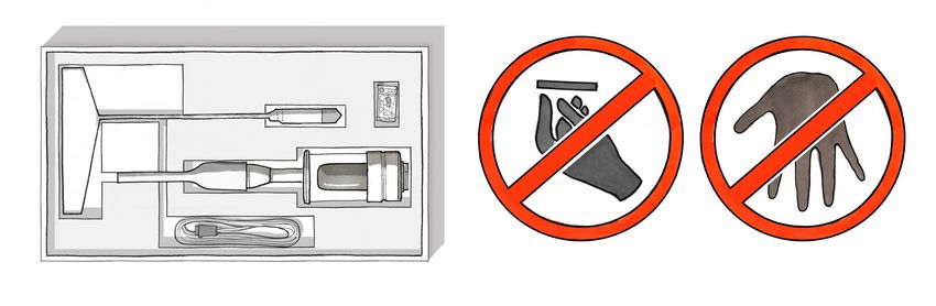
In case you want to order the Geovane MM along with a different Thies First Class /
Thies Compact part number, please contact sales@geovane360.com or
export@kintech-engineering.com.
Even though we do not offer in-house alignment for all the wind vanes on the market,
the following list of wind vanes is fully compatible with the Geovane MM:

 • Young Wind Monitor. (Default mechanics).
 • K360V. (Upon request).

For models not on this list please contact support@geovane360.com.

2.2.2 Geovane MM ordered without wind vane

Arriving at the customer, the delivery includes:

 • Geovane MM incl. vertical support boom* for the wind vane. (1)
 • 8-pole plug connector. (2)
 • 3mm Hex Wrench (Allen key) (3) and x2 DIN 916, M6x10mm grub screws.
 • Factory configuration sheet, quality control report and QR code to user guide.

*The vertical support boom has been redesigned and currently differs from the one
shown in the drawing below. It consists now of a single piece, without any adapters (see
picture on page 24).

 (3)

 (1)

 (2)

 Remark:

 This option requires precise alignment of the wind vane. Please carefully follow the
 instructions in chapter 5.

 11
2.2.3 Geovane MM ordered along with wind vane

Kintech offers complete “plug-and-play” units in which the Geovane MM has already
been aligned with a Thies wind vane (Compact or First Class).

In addition to the items described in section 2.2.2, the delivery includes:

 • Thies Compact / First Class wind vane coupled and aligned to the Geovane MM
 by Kintech Engineering. (4)
 • 5m of 0.5mm2 cross-sectioned shielded cable (number of cores depending upon
 wind vane model), already plugged and secured into the wind vane, ended in
 an IP68 in-line connector. (5)
 • Factory configuration sheet, quality control report and QR code user guide.
 • Wind vane documentation and alignment certificate.
 • Instructions on how to mount the tail of the TFC wind vane (if applicable).

Refer to section 5.2 for more info on the pinout and color scheme of the wind vane’s 5m
cable that comes already connected to the wind vane.

 (5)
 (1)

 (4)

 (2, 3)

Given that this is a “plug-and-play” unit, the only thing your installation team has to do
on site, is to mount this unit on the boom (refer to chapter 4).

 Remark:

 Both devices are aligned and ready to install. Do not untighten any of the screws or
 the alignment could be lost. Kintech Engineering marks the unions betweeen the wind
 vane and the geovane with white paint to allow its later verification.

 12
2.3 Geovane WT (for wind turbine)

The Geovane WTTM has been designed and engineered for its permanent installation on
wind turbines. The Geovane WT provides the exact orientation of the wind turbine
nacelle with respect to True North.

It is very common to encounter situations where the turbine does not orient itself
correctly in the direction of the wind. This is known as yaw misalignment. The state of
the art for detecting and correcting yaw misalignment comprises a number of
methodologies: LiDAR-based measurements, spinner anemometers installed on the
hub, control algorithms developed by the OEMs themselves and solutions based on
SCADA time series analysis.

Several of these techniques require knowledge of the absolute nacelle orientation
measured by the yaw encoder. Unfortunately, the yaw encoder data is not reliable since
their zeros are very often misoriented to True North. As a result, the SCADA receives the
orientation data with an offset of unknown value.

In addition to the zero-bias problem, incremental errors and reset-related errors are not
uncommon. All this means that, in practice, wind farm operators cannot make use of
the orientation data displayed by the SCADA. The Geovane solves this.

Although the purpose of the Geovane WT is to determine the absolute orientation of
the wind turbine’s nacelle, it is still possible to couple and align a wind vane to it, hence
Kintech offers the same wind vane alignment service and packaging than for the
Geovane MM.

 13
2.3.1 Geovane WT: order options and included items

The following two sections describe the content of the order options currently available
for the Geovane WT: with or without wind vane.

 Item Order code
 No wind vane Geovane009
 Geovane WT Potentiometer 2K
 Geovane010*
 4.3151.10.212
 Thies FC Potentiometer 10K
 Geovane011*
 wind vane 4.3151.10.110
 Analog output (TMR)
 Geovane012*
 + 4.3151.10.173
 Potentiometer 2K
 Thies Geovane013*
 4.3129.10.712
 Compact
 Analog output (TMR)
 wind vane Geovane014*
 4.3129.70.773
 Vector Potentiometer 1K
 Geovane018*
 wind vane W200P
*The Geovane WT and the Thies wind vane are supplied already coupled and aligned, in
a single packaging, as a plug-and-play unit.
In case you want to order the Geovane MM along with a different Thies First Class /
Thies Compact part number, please contact sales@geovane360.com or
export@kintech-engineering.com.

Even though we do not offer in-house alignment for all the wind vanes on the market,
the following list of wind vanes is fully compatible with the Geovane WT:

 • Young Wind Monitor. (Default mechanics).
 • K360V. (Upon request).

For models not on this list please contact support@geovane360.com.

 Remark:

 The Geovane WT needs to be accurately aligned with the turbine axis by means of the
 alignment collar and the laser alignment tool provided by Kintech Engineering (see
 section 4.6).

 14
2.3.2 Geovane WT ordered without wind vane

Arriving at the customer, the delivery includes:

 • Geovane WT (1)*.
 • 8-pole plug connector (2).
 • 3mm Hex Wrench (Allen key) (3) and x2 DIN 916, M6x10mm grub screws.
 • Alignment collar for the precise orientation to turbine nacelle’s axis (4).

 (3)

 (1)

 (2)

 (4)
*The Geovane WT can be ordered with a cover cap that includes the vertical support
boom for a wind vane, although the factory default consists of a flat cover cap.

2.3.3 Geovane WT ordered along with wind vane

Kintech offers complete “plug-and-play” units in which the Geovane WT has already
been aligned with a Thies wind vane (Compact or First Class).

In addition to the items described in section 2.3.2, the delivery includes:

 • Thies Compact / First Class wind vane coupled and aligned to the Geovane WT
 by Kintech Engineering.
 • Alignment certificate.

 15
• 5m of 0.5mm2 cross-sectioned shielded cable (number of cores depending upon
 wind vane model), already plugged and secured into the wind vane, ended in
 an IP68 in-line connector.

Refer to section 5.2 for more info on the wiring diagram of the coupled wind vane.

 Remark:

 Both devices are aligned and ready to install. Do not untighten any of the screws or
 the alignment could be lost. Kintech Engineering marks the unions betweeen the wind
 vane and the geovane with white paint to allow later verification.

2.4 Accessories

Besides the above-mentioned order options, Kintech can provide the accessories
displayed on the table below.

Items Geovane006 and Geovane007 are short wires that facilitate getting started with
the Geovane, allowing for office tests and for communication between a PC and the
Geovane (see section 4.3 and chapter 10). Item Geovane008 is necessary for the
alignment of the Geovane WT to the rotor axis of the wind turbine’s nacelle (refer to
section 4.6 for instructions regarding usage).

 Item Order code

 8-core cable with Geovane’s plug
 Geovane006
 connector soldered (1.5m)

 USB to RS-485 converter (1.8m) Geovane007

 Laser alignment tool including
 Geovane008
 Laserboy II (for Geovane WT)

 16
Item Geovane006 provides full access to the pins of the Geovane for e.g., verifying its
interfacing with a given data logger, re-configure the unit and, in general, run any office
tests. The color code for Geovane006 goes as follows:

 Pin* Color Description Function

 1 White Out (V1+) Analog output #1

 2 Pink RS-485 A RS-485 Data +

 3 Green Supply (+) Supply 6… 30V DC

 4 Grey RS-485 B RS-485 Data -

 5 Blue Out (V2+) Analog output #2

 6 Red Out (Hz) Frequency output

 7 Brown Supply (-) Supply ground

 8 Yellow Out (V-) Analog output ground

*Refer to section 4.3 for connector details and diagram.

Item Geovane007 converts from USB standard (PC) to RS-485 (Geovane). The color code
for Geovane007 goes as follows:

 Color Description Function

 Black GND Device ground supply pin

 Red Power* +5V

 Orange Data+(A) RS-485 Data +

 Yellow Data-(B) RS-485 Data -

*It can be used to power on the Geovane when configuring it (see chapter 10 for more
details), even though a minimum of 6V must be met in normal operation (see 6.1).

The green and brown wires of the Geovane007 item are not necessary for
communicating with the Geovane (they correspond to the 120Ω terminating resistance
terminals).

Refer to section 10.2 for detailed information regarding the interfacing of the Geovane
with a PC.

 17
3 UNDERSTANDING THE OUTPUT OF THE GEOVANE
This chapter aims to provide an understanding of the Geovane’s output: the True North
orientation. The Geovane is able to precisely determine True North using the position of
the Sun and can be accurately coupled and aligned with wind vanes and wind turbines
to get their orientation from True North.

When it comes to wind vanes, or any other wind direction sensor, the orientation from
True North is commonly known as “offset” and must be added to the raw wind vane
data to correct the dataset, as described in section 3.1. In the case of wind turbines, the
Geovane’s output indicates the orientation of the rotor axis of the wind turbine, as
explained in section 3.2.

3.1 Geovane MM + wind vane

Assuming proper alignment between the Geovane and the wind vane (refer to section
5.1), the Geovane will provide the offset of its attached wind vane with respect to True
North. Therefore, the true wind direction can be obtained by means of the following
equation:

 = + ℎ

The True North offset measurement is given in positive degrees, from 0° to 360°, and
clockwise from the True North, as describe in the next image.

 = 271° + 44° = 315°

 True North

 S

 18
A common oversight consists of applying to the raw wind direction, besides the offset
that the Geovane has provided, the boom orientation offset provided by the met mast
installer. This is completely wrong, and the final wind direction value will have an error
equal to the boom orientation inputted by the installer.

Refer to chapter 12 for further information on this topic.

3.2 Geovane WT

Assuming proper alignment between the Geovane and the wind turbine’s rotor axis
(refer to section 4.6), the Geovane will provide the instantaneous orientation of wind
turbine with respect to True North, provided sunny conditions.

 ′ = ℎ

The True North orientation measurement is given in positive degrees, from 0° to 360°,
and clockwise from the True North, as describe in the next image.

 Nacelle’s
 orientation
 (Geovane)

 19
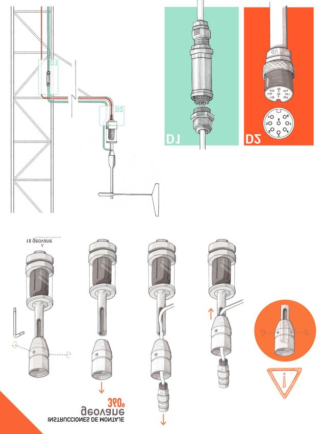
4 GEOVANE INSTALLATION (MECHANICAL AND ELECTRICAL)

If you have ordered the Geovane together with a wind vane, the unit (Geovane + wind
vane) has already been aligned by Kintech Engineering and the unit is ready for
installation in the field.

 Remark:

 Keep beacon lights and reflective surfaces out of Geovane field of view during day-
 time. If the light strikes the Geovane from an artificial source or reflection instead of
 directly from the Sun, the measurement will be temporally affected.

4.1 Installation overview and tips

The wind vane and the Geovane are not electrically connected in any way. From the
point of view of the wind vane, the Geovane is simply seen as mechanical support. This
means that the wind vane and the Geovane are individually connected to the datalogger
by means of two separate cables.

The typical configuration for a met mast is described in the drawing below, where D1
displays the connection inside an IP68-protected in-line connector between the short
cable coming from the wind vane and the long cable that goes down to the data logger,

 20
whereas D2 shows the Geovane’s 8-pole connector soldered to the a wire that runs
straight down to the data logger.

It is suggested that the wind vane’s cable is positioned in such a way that it runs down
the side of the Geovane facing the nearest Earth’s pole or the met mast. This is to reduce
the shadow projection caused by the cable, however this is by no means critical for the
accuracy of the measurements.

It is worth remembering that, once the Geovane and the wind vane have been aligned,
they must be installed together without modifying its accurately-established relative
orientation. This entails that the connector of the wind vane is not accesible any more
once the alignment is done.

In order to ease the installation procedure and avoid lifting the entire length of the cable,
we recommend using two cable sections for the wind vane, properly linked at boom
height, as detailed in the table below (and shown in the picture above):

 Sensor cable Length Connected via…

 From the sensor to the met mast
 (boom length)
 Wind vane IP68 in-line connector*
 From the boom to the logger

 Geovane From the sensor to the logger -

* For instance, Techno TEETUBE ® TH400 In-line Connector.

 21
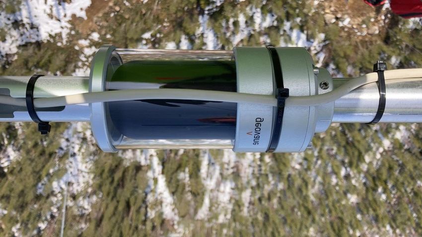
Remarks:

The Geovane housing features a mechanical slot intended to host a plastic cable tie
for fixating the cable that runs down from the wind vane, as shown in the following
picture. Failure to comply with this guideline may lead to excesive wear and tear of
the wind vane cable under harsh weather conditions.

 Fixate the wire of the wind vane to the body
 of the Geovane by means of a plastic cable tie

 22
Remark:

As described in 6.8, the Geovane rises the wind vane by aproximately 30 additional
cm. The length of the met mast vertical boom should be shortened so the wind vane
is kept at the same height that it would be in the abscense of Geovane. Therefore the
new length of the vertical support goes from D1 to D2, ensuring that D2 + D3 = D1
(see below).

 23
4.2 Mechanical mounting

The Geovane and wind vane must be mounted on an instrument carrier suited for it (e.g.
Ø34mm vertical tube). For dimensions of the Geovane please refer to section 6.8.

Tools required: 3mm Hex Wrench (Allen key), provided along with the Geovane.

Procedure:

 1. Push the cable of the Geovane through the borehole of the vertical boom and
 plug it into the connector in the base of the Geovane. Make sure the
 connection is correctly secured by manually tightening the connector.
 2. Fix the Geovane to its carrier (i.e. the boom) by tightening the two M6-Allen
 head screws.

 Remark:

 The inner diameter of the Geovane carrier (e.g. the boom) should be greater than
 20mm to allow enough room for both the plug and the cable to feed through.

 24
4.3 Connector details and diagram

All electrical connections are made to the Geovane via an 8-pole plug connector (DIN
45326) located in the base of the sensor housing. Each pole is identified, on the soldered
connection side, by a number.

The table below contains the pin assignment for the Geovane.

 Pin Description Function

 1 Out (V1+) Analog output #1

 2 RS-485 A RS-485 Data +

 3 Supply (+) Supply 6… 30V DC

 4 RS-485 B RS-485 Data -

 5 Out (V2+) Analog output #2

 6 Out (Hz) Frequency output

 7 Supply (-) Supply ground

 8 Out (V-) Analog output ground

Do NOT join pin 7 and pin 8 at sensor’s side. Use dedicated wires for each ground.
4.4 Cable details

The connector for the Geovane is suitable for use with cables with overall diameters of
up to 8mm and a core cross-section of 0.5 to 0.75mm2.

Depending on the number of pins to be used, the number of necessary wires can range
from three (frequency output) to eight. See section 4.3 for detailed pinout and chapter
10 for how to configure.

When using the analog outputs with cable lengths over approx. 100m it is advisable to
wire two cores in parallel for pin Out (V-). Refer to section 7.1 for a more detailed
explanation.

 25
Remark:

 It is recommended to always keep the RS-485 wires (pins 2 and 4) accessible from the
 ground so the Geovane can be re-configured and updated without having to dismount
 it from the met mast.

The following table shows the default color scheme for any 8-wire Geovane cables
supplied by Kintech Engineering:

 Pin Color Description Function

 1 White Out (V1+) Analog output #1

 2 Pink RS-485 A RS-485 Data +

 3 Green Supply (+) Supply 6… 30V DC

 4 Grey RS-485 B RS-485 Data -

 5 Blue Out (V2+) Analog output #2

 6 Red Out (Hz) Frequency output

 7 Brown Supply (-) Supply ground

 8 Yellow Out (V-) Analog output ground

It is critical that appropriate shielding is used to reduce EMI. The connection of the cable
shield depends on whether or not the mounting of the Geovane on the boom is isolated.

If the mounting of the Geovane is isolated (i.e., non-metallic adaptor sleeve), the cable
shield between the Geovane and the data acquisition system must be applied at both
sides. When the mounting of the Geovane is non-isolated (i.e., metallic adaptor sleeve),
the cable shield between the Geovane and the data acquisition system must be applied
one-sided at the data acquisition device.

Both cases assume that the metallic measurement mast and the data acquisition system
are grounded.

 26
4.5 Commissioning and troubleshooting

Prior to installing the Geovane, we strongly recommend that a bench system test be
carried out to confirm the system is configured correctly, is fully functional and
electrically compatible with the selected host system and cabling, preferably utilizing
the final cable length.

4.5.1 Commissioning: initial read values

It may happen that the Geovane is not able to update its True North orientation output
before the installation team leaves the site (for example, if the installation takes place
on a foggy day).

In order to verify that the Geovane has been correctly commissioned, the following
values must be checked:

 Output Variable Read value

 0… 360° (370° at startup, until the
 Analog voltage True North orientation Geovane is able to measure for the
 first time. See remark below.)
 (see 7.1)
 Tilt X / Tilt Y -90… 90°

 Frequency 0… 360° (370° at startup, until the
 True North orientation Geovane is able to measure for the
 (see 7.2) first time. See remark below.)

 Digital
 Any Answers polls
 (see 7.3)

 Remark:

 Before the Geovane gets GPS signal, the True North orientation outputs are set to
 380° (GPS fix is typically obtained 30 seconds after power on, provided open-sky
 conditions).

 27
4.5.2 Troubleshooting: output shows zero

Both analog voltage and frequency outputs distinguish between “live zero” and “dead
zero”. The 0% reading correspond to 0.5V and 10Hz respectively (live zero), whereas 0Hz
/ 0V are the “dead zero” (output not working).

These values allow for the quick diagnosis described in the table below:

 Output Variable Read value Diagnosis

 0V / -45° (dead zero) not working
 True North
 orientation 0.5… 4.5V / 0… 360°
 OK
 Analog (4.6V / 370° at startup*)
 voltage
 0V / -112.5° (dead zero) not working
 Tilt X / Tilt Y
 0.5… 4.5V / -90… 90° OK

 0Hz / -30° (dead zero) not working
 True North
 Frequency 10… 130Hz / 0… 360°
 orientation
 OK
 (133Hz / 370° at startup*)

 Digital Any Answers polls OK

*380° until the Geovane gets GPS signal (GPS fix is typically obtained 30 seconds after
power on, provided open-sky conditions).
Possible causes and solutions for “dead zero” reading:

1. The Geovane is not powered on → reset the Geovane and verify that the red laser
inside the Geovane switches on (power supply requirements on section 6.1).

2. Incorrect wiring → refer to section 4.3.

3. The output is disabled → enable the output (see chapter 11).

4. The analog output ground, Out(V-) at pin 8, is not connected (only required for Analog
voltage outputs) → connect Out (V-) to ground on the logger side.

 28
4.5.3 Troubleshooting: no response to digital commands

1. Verify wiring: pins 2 (RS-485 A) and 4 (RS-485 B) should be connected to Data + and
Data – of the RS-485 bus respectively. The Geovane should be powered on according
the specifications described in section 6.1.

2. Verify that the communication parameters match the requirements listed in section
7.3.

3. Verify that the commands have been correctly typed. Take into account that the
factory Listener ID is 00 and that it is user-configurable.

4.6 Wind turbine installation and alignment (Geovane WT)

The following eight drawings describe the mounting and alignment of the Geovane with
the wind turbine’s nacelle. A video on the alignment procedure is also available in the
following link: Geovane Wind Turbine video.

1. The Geovane WT needs to be accurately aligned with the turbine axis by means of the
alignment collar and the laser alignment tool provided by Kintech Engineering.

The Geovane WT is usually installed at the back of the nacelle, together with the rest of
the sensors used to control the turbine, although it can be installed where best fits the
user.

 1

It is advised to avoid installing the Geovane WT where large obstacles cause shadows on
the Geovane WT during long periods of time.

2. Every Geovane WT features an alignment collar (see 2.3.2), whose base has the same
diameter that the Geovane and the Thies FC sensors (refer to mechanical specifications

 29
in section 6.8). This alignment collar needs to be aligned to the axis of the nacelle and,
once aligned, fixated to the support.

Once the alignment collar has been aligned and fixated, the Geovane will be mounted
directly on it, accurately fitting in a unique position.

 Alignment
 collar
 2

3. To line up the alignment collar Kintech provides the laser alignment tool (see section
2.4). In the same way that the Geovane, the laser alignment tool is mounted onto the
alignment collar in a unique position, with both marking lines aligned with each other.

 Laser
 alignment
 tool 3

 Alignment
 collar

 30
4. Turn on the laser alignment tool and point to the desired nacelle axis reference. The
alignment laser tool has two degrees of freedom. The laser can be tilted up or down to
account for different sizes of turbines (it can point farther or closer as needed).

 4

5. Once the laser is pointing in the right direction, fixate the alignment collar by means
of its two screws without altering the alignment.

 5

 31
6. After fixating the alignment collar, remove the laser alignment tool.

 6

7. Push the Geovane’s wire through the alignment collar and connect it to the Geovane.

 Geovane
 7

 32
8. Place the already connected Geovane onto the alignment collar and tighten the
screws to fixate the Geovane in its final position.

 8

 33
5 GEOVANE + WIND VANE
In order for the Geovane to measure the offset from True North of the coupled wind
vane, both devices must have their internal angular references perfectly aligned with
each other.

If you have purchased the plug-and-play solution described in sections 2.2.3 and 2.3.3,
in which the Geovane comes coupled to the wind vane, this alignment has already been
carried out by Kintech Engineering, the only thing you need to take care of is not altering
the alignment when installing the pack on the met mast (see section 5.2 for information
on the wind vane’s color code wiring).

5.1 Geovane + wind vane alignment

In case you have ordered the Geovane without a wind vane, or you need to align the
Geovane with a new wind vane, please follow this procedure.

The alignment between Geovane and wind vane is based on the wind vane’s electrical
signal and not on the North Mark of the wind vane. In this way, both the potential
installation error and the positioning error of the north mark made by the manufacturer
are eliminated.

The accurate relative orientation between the Geovane and the wind vane is achieved
through a precision laser-technology inside the Geovane.

STEP 1: loosen the two M6-Allen head screws to feed the cable of the wind vane through
the adaptor sleeve, as shown below.

 34
Remark:

 The vertical support boom has been redesigned and currently differs from the one
 shown in the drawings below. It consists now of a single piece, without any adapters
 (see picture on page 24).

STEP 2: power on the wind vane, connect it to the data logger and turn its tail until it
outputs exactly 180°.

 35
STEP 3: while the wind vane is outputting exactly 180°, block the wind vane.

STEP 4: power on the Geovane. The Geovane will activate its line laser emitter for the
next five minutes. With the wind vane still locked at 180°, turn the wind vane from its
base until the laser line hits the tail. When this happens, the angular references from
both sensors match. With the laser still projected on the wind vane tail, tighten the Allen
screws on the wind vane base to fix it to the Geovane.

Once the two devices are aligned, the complete unit must stay fixed in this position and
is ready for use.

 36
Remarks:

 Laser beam emitter (Class 1) is hard to detect outdoors during daylight hours:
 alignment in the workshop is strongly encouraged.

5.2 Wind vane color code wiring (plug-and-play option)

This section describes the wind vane’s color code wiring for the Geovanes ordered along
wind vanes as a complete “plug-and-play” unit, in which the Geovane has already been
aligned with a Thies wind vane (see sections 2.2.3 and 2.3.3).

Depending upon the wind vane type you have chosen, the color code for the 5m of
0.5mm2 cross-sectioned shielded cable already plugged and secured into the wind vane
and ended in an IP68 in-line connector, will differ, according to the following tables:

 Thies potentiometer pinout
 Description Color
 First Class Compact

 1 3 SIG (Potentiometer wiper) White

 2 2 GND (Ground) Brown

 3 4 +US (Power supply) Green

 Yellow
 Shield
 Green

 Thies TMR pinout
 Description Color
 First Class Compact

 1 3 SIG (Analog output) White

 2 2 GND (Supply ground) Brown

 3 1 +US (Power supply) Green

 6 4 AGND (Analog ground) Yellow

 Yellow
 Shield
 Green

 37
5.3 Thies First Class wind vane: how to mount its tail

The tail of the Thies First Class wind vane comes separately and must be mounted on
the body following these instructions:

 1. Unscrew the cap from the upper part of
 the wind vane.

 2. Put the tail of the wind vane onto the
 upper part of the body and turn it until it
 falls and locks into the single position.

 3. The marking lines of the tail and the body
 must be aligned with each other.

 4. Put the cap onto the thread and screw it
 strongly by rotating it clockwise by hand.

 Remark:

 The longer part of the tail’s blade must indicate upwards.

 38
6 TECHNICAL DATA

6.1 Operation conditions

 Description Value Units Comments

 12 V (DC) Recommended
 Operating voltage
 6 V (DC) Minimum

 Remark:

 The power supply should be able to provide at least 80mA to account for the
 maximum current peak Geovane might demand.

6.2 True North orientation measurement

 Description Value Comments

 Reference Geographical North True North

 Measurement Range 0… 360° Clockwise rotation
Remark:

 Before the Geovane gets GPS signal, the True North orientation outputs are set to
 380° (GPS fix is typically obtained 30 seconds after power on, provided open-sky
 conditions).

 Once the Geovane has obtained GPS signal and until it is able to measure for the first
 time, the True North orientation outputs are set to 370°. In this way, the installer can
 verify that the Geovane is operating properly even in the absence of sunlight (see
 4.5.2).

6.3 Tilt measurement

The Geovane is equipped with an internal 2-axis tilt sensor that permits it comparing the
theoretical and observed solar azimuth angles even if the Geovane is not perfectly
leveled. The tilt measurement is also provided as output to help verifying the instrument
mounting on the boom.

For an accurate absolute measurement of the tilt angle with respect to horizontal, every
Geovane’s tilt sensor is factory calibrated relative to a high-precision independent
bubble level across a -10 to 60°C temperature range. The temperature correction
coefficients of the tilt measurement are programmed during production and are
available in the quality certificate that comes with the unit. The tilt sensor has an
absolute accuracy of
6.4 Absolute maximum ratings

 Description Minimum value Maximum value Units

 Input voltage 0 30 V

 Operating
 -25 85 °C
 temperature

 RS-485 input voltage -10.5 10.5 V

6.5 Average current consumption

 Description Duration mA*

 Sleep mode Night-time 1.5

 Laser ON 5 min at startup 16

 GPS ON 30 seconds at sunrise / startup 17.8

 Measuring mode Day-time 5

*Typical. Powered at 12V DC. Only digital output activated.
Depending on which outputs are activated, the current consumption increases
accordingly to the following table:

 Description mA

 Frequency output activated 1.1

 One analog voltage output activated 0.7

 Both analog voltage outputs activated 0.8

 41
6.6 Mechanics

 Description Value Comments

 Weight 0.815Kg Incl. wind vane adaptor

 Dimensions See section 6.8

 Anodized aluminum Main body
 Housing material
 Borosilicate Glass 3.3 Glass tube protector

 Protection Class IP67 -

 Mounting Onto mast tube Ø34mm (Thies FC carrier)

 Ø wind vane adaptor
 34mm External diameter
 sleeve

6.7 Outputs summary

 Output Description*

 Digital (x1) RS-485, 4800/9600/19200/38400 bps, 8N1

 10… 130Hz, 0-5V square-wave signal, push-pull, 50% duty
 Frequency (x1)
 cycle, 50mA of drive capability

 Analog voltage (x2) 0.5… 4.5V, 12-bit resolution, 12mA of drive capability

*Refer to chapter 7 for detailed information.

 42
6.8 Dimensions (mm)

6.8.1 Geovane

 43
44
6.8.2 Alignment collar’s dimensions (Geovane WT)
Refer to sections 2.3 and 4.6 for further details on the alignment collar.

 45
7 SENSOR OUTPUTS
The Geovane offers three types of outputs, summarized in the below table:

 Output* Number Data Range Comments

 0-5V, push-pull, 50% duty
 True North
 Frequency x1 10… 130Hz cycle, square-wave, 50mA
 orientation
 of drive capability

 True North
 Analog 12-bit resolution, 12mA of
 x2 orientation / Tilt 0.5… 4.5V
 voltage drive capability
 X / Tilt Y

 4800/9600/19200/38400
 Refer to chapters
 RS-485 x1 - bps, 8N1, NMEA 0183,
 8 and 9
 Modbus RTU

*For information on pin connections see section 4.3. For information on output
configuration refer to chapter 11.

7.1 Analog voltage outputs

Each of the two analog voltage outputs can be configured to one of the following:

 • True North orientation (see section 6.2).
 • Tilt X (see section 6.3).
 • Tilt Y (see section 6.3).

Both analog voltage signals are digitally generated by means of a 12-bit 0-5V Digital to
Analog Converter and subsequently conditioned by an analog output stage with 12mA
of drive capability. The output is constrained to the range 0.5-4.5V, leading to the
following characteristics:

 Variable Variable range Voltage range Resolution

 True North orientation 0… 360° 0.5… 4.5V 0.11°

 Tilt X / Tilt Y -90… 90° 0.5… 4.5V 0.05°

The first analog voltage output, Out (V1+), is located at pin 1.

The second analog voltage output, Out (V2+), is located at pin 5.

Both analog outputs reference its voltage to Out (V-), located at pin 8. In order to ensure
proper signal integrity, Out (V-) must never be connected to Supply(-) on the sensor

 46
side. Otherwise, the voltage drop in the negative power line will affect the accuracy of
the measurement.

The True North orientation can be calculated from the measured volts according to the
following equation:

 ℎ = ∗ 90 − 45

Both Tilt X and Tilt Y can be calculated from the measured volts according to the
following equation:

 = ∗ 45 − 112.5

One way to maximize the accuracy of the analog voltage outputs when using cable
lengths over approx. 100m is by reducing the total resistance in the return path that
runs from pin Out (V-) to the logger, either by increasing the cable cross-section or by
wiring two cores in parallel for pin Out (V-).

Current flowing through Out (V-) is constant and around 800µA. To help you decide
whether or not the voltage drop along the analog return path is admissible the following
equation can be used as a benchmark:

 = −

 = ∙ = ∙ ( ∙ ) = ∙ ( ∙ ∙ 800µ )

For instance, for 92m of 0.5mm2 cross-sectioned copper wire, the theoretical True North
offset error, given in degrees, would be:

 92
 = 90 ∙ (0.0172 ∙ ∙ 800µ ) = +0.228°
 0.5

If two cores are wired in parallel for Out (V-), the theoretical drift is reduced by half:

 92
 = 90 ∙ (0.0172 ∙ ∙ 800µ ) = +0.114°
 2 ∙ 0.5

7.2 Frequency output

The frequency output can be configured to:

 • True North orientation (see section 6.2).

The frequency output consists of a 0-5V digitally-generated 50% duty cycle square-wave
signal, subsequently buffered by a push-pull output stage with 50mA of drive capability.
The below table specifies its characteristics.

 47
Frequency
 Variable Variable Range Resolution
 Range

 0.01° 0.16°
 True North
 0… 360° 10… 130Hz
 orientation
 (average) (worst case)

The frequency output, Out (Hz), is located at pin 6.

Out (Hz) references its voltage to Supply (-).

The True North orientation can be calculated from the measured hertz according to the
following equation:

 ℎ = ∗ 3 − 30

7.3 RS-485 digital output

The digital output of the Geovane can provide the following information:

 • True North orientation (see section 6.2).
 • UTC data and time the last True North orientation measurement was taken.
 • Tilt X and Tilt Y (see section 6.3).
 • 3-axis vibration (Geovane WT only).
 • Sun’s coordinates (azimuth, altitude, declination, hour angle).
 • GPS coordinates.
 • Date and UTC time (GPS).
 • Internal temperature.
 • Geovane’s hardware status (self-test function).
 • Geovane’s current configuration.
 • Serial number, firmware and hardware version.

The Geovane is equipped with an RS-485 half-duplex serial interface (4800 / 9600 /
19200 / 38400 bps, 8N1). Reduced-slew-rate drivers are used in order to minimize EMI
and reduce reflections caused by improperly terminated cables. Over the RS-485
interface, the Geovane implements two communication protocols:

 • NMEA 0183, described in chapter 8.
 • Modbus RTU (Geovane WT only), described in chapter 9.

If two or more Geovane units are to be installed it is possible to use the same 2-wire
data link to connect all the Geovane units to a master, provided that each Geovane is
configured with a different listener identifier (Listener ID / Modbus slave address).
Before using a Geovane in a multi-device system, the Listener ID of each Geovane must
be set to a unique value (refer to chapter 11).

 48
The digital output has timing constraints. When a valid command is received by the
Geovane input buffer, there will be a delay time while the command is being processed.
The delay between the command and the output message is defined by the time t1 and
it depends on the internal processing cycle.

 Command t1 Output message t2

Once the last byte of the output message is sent by the Geovane, there must be an
additional delay t2. This delay time ensures that the state of the internal driver is set to
high impedance and, therefore, the driver is able to receive a new command. Thus, the
poll frequency is limited by both delay times and baud rate. It is strongly recommended
that the poll frequency does not exceed 4Hz, i.e., 4 commands per second.

The default configuration corresponds to a baud rate of 9600 bps. The baudrate is user-
configurable via Geovane Tools software (see section 11.1) to any of the following
options:

 • 4800 bps.
 • 9600 bps. (Default).
 • 19200 bps.
 • 38400 bps.

The following table summarizes the timing constraints (typical values):

 Description Value Units

 Delay command-output message t1 6* ms

 Delay after output message t2 4** ms

 Maximum poll frequency 4 Hz

*Maximum.
**Minimum.
The Geovane features an internal 120 Ω termination resistor that can be configured to
be connected or disconnected by the user (refer to chapter 11).

 49
8 RS-485 DIGITAL OUTPUT: NMEA 0183
The digital communication protocol follows a master-slave format, where the Geovane
is the slave and an external device is the master. The master should send a command
(list available in section 8.2), and the Geovane will answer the corresponding output
message (section 0). Please refer to section 7.3 for general information on the RS-485
digital output of the Geovane.

All messages follow the NMEA 0183 standard. Every standard NMEA message begins
with ‘$’ character (hex value 0x24) and ends with a Carriage Return (hex value 0x0D) and
Line Feed (hex value 0x0A).

Following the start character comes the device identification, ‘GV’ for a Geovane device.
The next three characters specify the message identification. After the message
identification begin the data field delimitated by commas (‘,’). The end of data fields is
indicated by the character ‘*’.

The message includes a checksum field consisting in a bitwise XOR of all characters
between (but not including) Start character ‘$’ and End-of-data character ‘*’. The
resulting single byte value is then represented by two hexadecimal characters in the
message string, as shown in the example below. The most significant character is
transmitted first.

 Characters used to
 calculate the checksum

 $ P M G V 0 1 , 0 0 * 2 1 Hex Values

 30

 30

 2C

 31

 30

 56

 47

 4D

 50

 XOR result: 21

The Geovane is assigned with both a Listener and a Talker identifier address that allows
an individual Geovane to be uniquely identified in a system comprising more than one
Geovane. Whenever a message is sent to the Geovane, the identifier field of the
message must correspond to the Geovane Listener identifier address, otherwise the
Geovane will ignore the message.

 50
In applications where more than one Geovane is connected to the RS-485 bus, you
should assign each Geovane in the system a unique Listener ID. The master will then be
able to address individually each Geovane.

 Parameter Factory settings Selectable values

 Baudrate 9600 4800, 9600, 19200, 38400

 Data bits 8 8

 Parity None None

 Stop bits 1 1

 Listener ID 00 00, 01, 02, 03… 99

8.1 Answers from the Geovane

This section describes all the messages sent by Geovane after receiving poll requests
from the master (section 8.2).

8.1.1 ORN message: True North orientation

$GVORN,274.20,+01.20,-00.80,01,00*7F

 Field Example Description

 Start character $

 Talker identification GV Geovane identification

 Message ID ORN Identifier associated to the type of message

 True North orientation* 274.20 Angle between True North and the device
 reference, in degrees
 Range: 0… 360°

 X-axis tilt angle** +01.20 Angle between the X-axis and the horizontal
 plane in degrees
 Range: -90… 90°

 Y-axis tilt angle** -00.80 Angle between the Y-axis and the horizontal
 plane in degrees
 Range: -90… 90°

 51
You can also read