Single microwave photon counter based on current biased Josephson junction - Alessio Rettaroli
←
→
Page content transcription
If your browser does not render page correctly, please read the page content below

Single microwave photon counter based on
 current biased Josephson junction
 Alessio Rettaroli,
 on behalf of the SIMP collaboration1
 (1. see last slide)

La = Ka Fµ⌫ F ,
ember that Ka is 4⇡ fa
 a dimensionless model-dependent parameter. The interaction
 Wecompactly
 usemodel-dependent
 is a dimensionless
ewritten more Josephson junctions
 coupling as
 parameter.
 defining the Thephoton ga detectors
 interaction
 constant : for axion search
 ompactly defining the coupling constant ga :
 1
 1 La µ⌫ = ga aFµ⌫ F̃ µ⌫ , (1.47)
 La = ga aFµ⌫ F̃ , 4 (1.47)
 4 arise from extensions of the
 Axions
 Standard Model of particle physics
 and↵are good candidates Ka
 ↵ofemDark
 em K a ga = . (1.48)
 ga = .
 Matter ⇡ f a (1.48)
 ⇡ fa
 has dimensions
 1 GeV 1
 but is still model-dependent.
 s GeV but is still model-dependent. It isthat
 It is important to note important to note that
nversely
 ional to proportional to the
 the scale constant fa .scale constant the
 Furthermore, fa . electromagnetic
 Furthermore, the electromagnetic
on can in
written also be written
 terms of the inhave
 terms
 electric
 Axions and ofmagnetic
 the electric
 an interaction and
 fields, themagnetic
 components fields, the g
 a components
 ⌫ tensor: term with photons
 1 1 ~ µ⌫ = ga a E
 ~µ⌫· F̃ ~ · B.
 ~ (1.49)
 La = ga aFL µ⌫
 µ⌫aF̃ = = ggaa aFaE B. Axions from (1.49) Photon
 4 4 DM halo detector
 derived
ality in appendix
 is explicitly A of in
 derived Ref. [7]. ThisA
 appendix expression becomes
 of Ref. [7]. useful
 This expression becomes useful
axion
aling conversion into photons
 with the axion in a into
 conversion detector, suchinasaadetector,
 photons microwavesuch as a microwave

 A. Rettaroli, WOLTE14 - 2021 1
 tly the same form as the Primakoff process [27], that was first
 (1.49) has exactly the same form as the Primakoff process [27], that was first

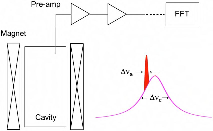
Q ¼ Q=ð1 þ %Þ, Q being the unloaded or intrinsic quality
 ers c Qc ¼ Q=ð1 þ %Þ, Q being the unloaded or intrinsic quality
 factor,
 factor, % the
 and and % ratio of power
 the ratio coupled
 of power coupledout by
 Haloscopeoutthe antenna
 byconcept
 the antenna
hat
 to power dissipated
 to power by cavity
 dissipated wallwall
 by cavity losses. TheThe
 losses. fraction of of
 fraction
 ers
the
MX SIMP (SIngle Microwave Photon) project
 ata
ave
 to
ble
 hysics case 1.2. Searching for axions
 or
 ith
ved
hat
 do
 be
 Localized power excess
ons
 tch of a microwave cavity in which an axion-photon conversion occurs. Taken
 FIG. 1
 FIG. cryostat
 (color
 1 online).
 (color online).Simplified schematic
 Simplified schematicof the
 of microwave
 the microwave
atic
 1].
 cavity search
 cavity for halo
 search axions.
 for halo The The
 axions. insertinsert
 depictsdepicts the virialized
 the virialized
 & ! 6 ) within
 6 ) within
 axion signal
 axion
haloscopes (Q
 signala (Q a &
 E=!EE=!E 10! 10 the Lorentzian
 A. Rettaroli,
 the WOLTE14 band-
 - 2021
 Lorentzian band- 2
D. Driven junctions
 Current biased Josephson junctions as photon detectors
The Josephson relations (13.41) and (13.37)

 I 5 Ic sin φ In order to use a JJ as a detector, it is convenient to bias it with a dc current just
 ð13:48Þ
 = # sin below ! through a suitable dc current source.
 d 2e
 φ 5 V; ð13:49Þ
 The occurrence of an external additional current can induce the switching of
 dt h̄ the junction from the zero to the finite voltage state.
 Kuzmin et al, IEEE Trans. Appl. Supercond., VOL. 28, NO. 7 (2018)

apply to an idealized case in which all the current is carried by electron pairs. In
 SIMP SCIENTIFIC PROPOSAL
the more general case, there can be other types of current flowing, such as displace-
ment current, quasiparticle tunneling current, and perhaps conduction current, if the
barrier is not a perfect insulator. It will be instructive to analyze the junction in
terms of the equivalent circuit shown in Fig. 13.35, which contains the current
source Ic sinφ of the junction, a capacitor to represent the displacement current, and

 Figure 7: Washboard potential describing the dynamics of the superconducting phase of a CBJJ.
 A. Rettaroli, WOLTE14 - 2021 3
 The voltage drop across a junction is related to the phase variation in time:

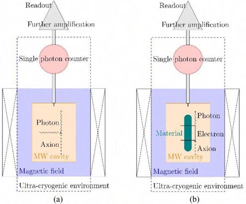
axion-cavity experiments was already discussed in [10]. The
ccepted May
 ion July 19, Critical
 detected noise power from a linear amplifierrequest:
 is given bylow
 the dark counts
 under Grant Dicke relation [11]
R. Cristiano. !
 ∆νa
 Gothenburg Plin = kB T (1)
l University, ▸ We expect
 t tiny signals from axions: !" ≲ 10#$% TABLE II
 PARAMETERS FOR EXPERIMENT FOR AXION DETECTION WITH
 where kB is Boltzmann constant, ▸ Single
 T is photon
 temperature (for have
 detector better noise performances MAGNETIZED MEDIA
 negligi-
 neering and
 ia, and also ble noise temperature), ∆νa = with νc [GHz] × 5.2
 respect 10−7 amplifiers
 to·linear [8] is the above about 10
University), axion signal bandwidth, and t is the integration time. This equa-
 ori Nazion-
 tion1.must
 Fig. be modified
 Detection scheme at forlow
 two temperatures to take
 different processes into account
 involving a galactic
 axion. (a) Axion passing through a static magnetic field can be converted into
om; daniele. zero-point fluctuations [10]
 a photon by meansRMS of theofinverse
 noisePromakoff
 power for linear
 effect. amplifiers:
 (b) Axion can resonantly
 !
 interact with an electron in a static magnetic field, causing a spin-flip that
ova I-35131, ∆νa
, Legnaro I-
 = %&/( )
 1 eventually decays into P =
 a photon.
 lin hν (n + 1) (2) "#$ Δ '
 ! −1 t ≈0 ≈
 sity,Δ Nizhny #$
 %& ()
 ! = " ⋅ 10
 where h is Plank constant, ν is the photon frequency, and n is
 1 2 The analogous relation for aphoton
 single photon counter (SPC) is0
 Δ " = = the photon
na D-07702,
 "
 "
 and
 occupation for single
 number in the counters:
 cavity. Even when n ≈ () ≈ 10
 zero-point fluctuations limit then∆ω ! effective temperature to hν/kB ,
ilable online c + νDC at 10 freq
 known as the standard Psp =quantum
 hν limit. It corresponds to about (3)
 t
 700 mK at 14 GHz.
 where ∆ωc = 1/τc is the inverse of the cavity lifetime and νDC Srednicki–Zhitnitsky [14] model is
 permitted, but is
 CBJJs have the potentiality to reach dark counts atPmHz
 republication/redistribution
 the device dark count requires
 rate.IEEE permission.
s standards/publications/rights/index.html for more information. rate. −26 W
 signal = 3.6 × 10
 At very low temperature, about 20 mK, thermal photons are
 negligible and (2) and (3) are reduced to
 ! corresponding to a rate of photon Rsig = 0.004 Hz. While rea
 !
 ∆νa νA.DCRettaroli, WOLTE14 - 2021ing a signal-to-noise ratio of about 3 is practically
 4 impossi
 Plin = hν and Psp = hν . (4) with a linear amplifier, with a fully efficient SPC of maxim

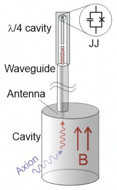
68 the Josephson junction, for certain dc bias current intervals, where two voltage states (zero and finite
 f the
about
 69
 excited
 value) 10bephotons
 can JJ to the
 observed. Such resistive
 from a 50
 hysteresis state.
 is at W base
 the TL, The highest
 induces
 of the probability
 use of JJ as a switch
 detector. ofisthe
 It is worth obtained
 notingjunction.
 that, when gTL = gswitch .
 alues of 50 W TL and Cj ⇠ pF gTL ⇠ 100 GHz the reflection is high provided the switching
 in a typical tunnel type Josephson junction, the resistance of R J strongly depends both on voltage and
 Switch in presence of signal
 70

 71 temperature. However, as the overall effect of the resistor is to introduce dissipation in the system, its
tion
 same
 72 orderis or
 nonlinearity oftenanot
 proper circuit
 considered, for of
 in presence impedance
 moderate or weak matching is designed.
 damping. Another important In the next scetion we
 effect of the quasiparticle current, modeled by R J , is the presence of random charge fluctuations, which
numerical simulation used to estimate the JJ parameters suitable for a photon counter. In
 73

cs with
 74
 of aI inCBJJ in presence adensity
 microwave pulse wave, representing
 can be represented , through the fluctuation dissipation theorem, by a noise current source, indicated
 a single photon
we estimated
 75 n Fig. 2 that
 whose in thepower
 spectral simplest device
 is assumed (TL+JJ) pulses
 to be frequency of peak
 independent current of about 250 nA,
 (Johnson
 ennoise)
 76 investigated
 [44]. by means of numerical simulation of the model equations [54].
 ng to about 10 photons from a 50 W TL, induces Thea switch
 simplest of design
 the junction.
 for a photon detector is a
descrizione simulazione co RC in parallelo per simulare linea di bias. Mettere risultati
 transmission line (TL) terminated with a JJ
 isolata e con R=50 ohm in parallelo (linea di trasmissione).
 mulation
 simulation results to the device composed of a TL terminated to a JJ we compare
 namics of a CBJJ in presence a microwave pulse wave, representing a single photon
he
 hasequation for the flux
 been investigated variable
 by means in a TL terminated
 of numerical simulation ofby
 thea model
 parallel LC (a linearized
 equations [54].
 gere descrizione simulazione co RC in parallelo per simulare linea di bias. Mettere risultati With a 7 = 600 Gaussian wavepacket,
 f 1 1 in in
 per JJ isolata e conCR=50 f̈ + + ohm in parallelo
 ḟ = 2 ḟ = 2I (linea di trasmissione). (14) switches when:
 the junction
 L
te the simulation results to the 0device composed
 Z Z 0 of a TL terminated to a JJ we compare
of a single
with photonfor
 the equation onthe theflux waveguide
 variable in with a TL a Gaussian
 terminated wavepacket
 by a parallelofLC
 time duration st
 (a linearized
 Circuit equation with flux variable
 #$
 2 f 1h̄w 0 2 1 in in
 • 2 = when isolated,
 C f̈ I+ peak =
 + ḟ =p 2 ḟ = 2I (15)
 (14)
 corresponding to 4 photons
 Figure 2. (a) Electrical model of a JJ with L
 intrinsicZ Z
 and 0
 0 external Z0 sources.
 2ps
 current t (b) Electrical model of a JJ
 attached to a transmission line. (c) Electrical model of a JJ with a parasitic RC load.
rrent
de of of
 thea single
 signalphoton
 currentonI the waveguide with
 corresponding toaaGaussian wavepacket
 single photon is of time duration s#$t
 Peaks current for 1 photon • 2 = with a 50 Ω TL,
 2
 s h̄w0 2 corresponding to 100 photons
 I
 photon peak = h̄w p 2
 0 2ps
 (15)
 Is =2 Z0 p t (16)
 Z0 2ps
mplitude of the signal current Is corresponding tot a single photon is
 ton with st = 600 ps on a 50W TL,s this corresponds to about 26 nA.
 photon h̄w0 2 A. Rettaroli, WOLTE14 - 2021 5
 Is =2 p (16)
 Z0 2ps
74 can be represented
 123 , throughdiffusion
 the fluctuationregimes that will
 dissipation theorem, regulate
 by a noise the indicated
 current source, escape process.
 with In in Fig. 2 whose spectral power density is assumed to be frequency independent (Johnson
 75
 124 B) The measure of the escape rate at different values of the DC bias bias current, I , at fixed temperature.
 f a microwave photons signal is generated, for example
 76 noise) [44].
 Dark due to
 counts the axion-matter
 125 This second method can better define the right bias current value for the detection of the RF
 tive possible
 126
 dynamics of the CBJJ will be described from
 signal generated by the axion interaction.
 the specific initial quantum
 th the exciting RF signal, which will have triggered SIMP SCIENTIFIC
 the escape PROPOSAL
 process [33,35]. In
ple, the entanglement
 127 In between
 particulardifferent
 if a microwave
 states photons signal
 of the CBJJ is generated,
 involved by thefor RFexample
 signal due to the axion-matter
 128 interaction, the relative possible dynamics of the CBJJ will be described from the specific initial quantum
 (Rabi effect) [33,51,52]. Even a second configuration in detecting the RF signal is
 129 state connected with the exciting RF signal, which will have triggered the escape process [33,35]. In
ng a Qubit where
 130 thisthe RFfor
 case, signal has the
 example, been stored in addition
 entanglement to a CBJJ
 between different can of
 states detect theinvolved by the RF signal
 the CBJJ
 states beetwen
 131 two
 can bedevices [53].(Rabi effect) [33,51,52]. Even a second configuration in detecting the RF signal is
 highlighted
design for a132photon detector
 possible is a transmission
 when using a Qubit whereline
 the (TL) terminated
 RF signal has beenwith
 storeda JJ. In this to a CBJJ can detect the
 in addition
 133 apossible
 robability for photonentangled
 to cause thestates beetwen of
 transition two devices
 the [53].to the resistive state is:
 junction
 TheProbability
 simplesttodesign cause afor transition:
 a photon detector is a transmission line (TL) terminated with a JJ. In this
 configuration the4g probability
 gswitch
 TLexternal for a photon to cause the transition of the junction to the resistive state is:
 Figure 2.
 P =
 (a) Electrical model of a JJ with intrinsic and current sources. (b) Electrical model of a JJ
 Figure 7: Washboard potential describing
 R Electrical model of a JJ with a parasitic RC
 attached to a transmission line. (c) 2 load. %* ∼ 10the dynamics
 ! of the
 +
 ∼ 10 phase of a CBJJ.
 (gTL + gswitch ) ,-superconducting
 4gTL gswitch
 PR =
 q The voltage(gdrop gswitcha)2junction is related to the phase variation in time:
 TL +across
/Z0 = 2p/Z0 Cj and Zj = of
 Coupling /Ctoj (referenze
 L jTL the junction: Romero, Flurin, ...), and
 • g is maximum
 8switch is the when 9: = ;< , but = = 1 MHz
 q
xcited JJ to the
 134 where gTL
 resistive state. j Z j /Z
 = wThe 0 = 2p/Z
 highest 0 C j and Z jis=obtained
 probability L j /Cj (referenze
 when• gTL 8Romero,
 ==0.5 U⋅ 10
 =
 gswitch V
 #>
 Flurin, /2X
 . Wwhen...),⋅ YZ
 and=Y,
 ;< MHz,is the
 g1switch = = 1 kHz

of 50 W TL and switch rate of the excited JJ to the resistive state. The highest probability = 4 ⋅ is
 10obtained when gTL = gswitch .
 C j ⇠ pF gTL ⇠ 100 GHz the reflection is high provided • the
 8 switching #? when
 ;< = 1 kHz, = = 1 Hz
 135

 For typical values of 50 W TL and Cjleading
 circuit for impedance matching⇠ispFdesigned. gto ⇠ 100
 TLtwo GHz states:
 thethe reflection
 scetioniswehigh provided the switching
 distinct A zero-voltage state, when the state is trapped inside a
order or a proper
 136
 In next
 137 rate is of the same order or a properminimum circuit forof
 impedance
 the potential matching is designed.
 with constant phase;InAthe next scetion
 voltage, we
 or resistive, state with a vo
 cal simulation used to estimate the
 discuss the numerical simulation
 JJ parameters
 used
 suitable
 droptoofestimate
 for a photon counter. In
 138
 Proper matching of the TLthe
 hundreds to JJ
 of theparameters issuitable
 junctionwhen
 microvolts, an the
 issue for aisphoton
 state free of counter. In
 running along the washboard
mated that 139in the simplest
 particular, wedevice
 estimated (TL+JJ) pulses
 that in thephase ofincreases
 peak
 simplest current
 device of about
 (TL+JJ)
 with time. pulses 250 nA,
 of peak
 This system cancurrent of about
 be considered as250 nA,
 a quantum system (for lo
 bout 10 photons
 140 from a 50 WtoTL,
 corresponding aboutinduces a switch
 10 photons fromof
 enough theWjunction.
 a temperature)
 50 TL, induceswith aanswitch of the
 effective junction.
 cubic potential. If the ground state has a neglig
 A. Rettaroli, WOLTE14 - 2021 6
 tunneling across the barrier, the system is blocked in the well. The absorption of a pho
Possible solutions to the matching issue

JJ directly coupled to a 3D cavity Stub tuner
 2

 b mode at wc /2p ⇠ 8 GHz, which is used for readout and con-
 a
 trol. This location also nulls the coupling to the second mode
 (TE102 at approximately 10 GHz).
 β=1 Despite the larger mode volume of the three-dimensional
 cavity, we are able to achieve the strong-coupling limit of cav-
 ity QED in this system, with vacuum Rabi frequencies, g/2p,
 greater than
 Ζ0 100 MHz. As seen in Stub
 Cavity+cable+ Figure 1b, the electrodes of
 Tuner
 the qubit are significantly larger (⇠ 0.5 mm) than in a conven-
 250 µm
 c arXiv:1105.4652v4
 50 mm
 tional transmon qubit, so that the increased dipole moment of
 -60 3D resonant cavity Antenna 15
 the qubit
 Coaxcompensates
 Cable for the reduced electric field
 Openthat a sin-
 -70 gle photon creates in the cavity. We note that due to the large
 -80
 dipole moment, the expected lifetime from spontaneous emis-
 Pin (dBm)

 10

 VH (mV)
In this case-90decoherence is given by @ sion in free space would be only ⇠ 100 ns, so that a high-Q
 -100
 5 cavity is required to maintain
 If there is nothe qubit lifetime.
 matching, The elec-
 the photon is
 So, for copper
 -110
 cavities gat
 2
 /δ10 GHz:
 -120 trodes also form the shunting capacitance (C S ⇠ 70 fF) of the
 ‘trapped’ in the coplanarand branches
 0
 -130 @ ∼ 1 transmon, giving it the same anharmonicity the same in-
 sensitivity to 1/ f charge noise as in the conventional design.
 @ = 1/ @ ∼ 1 MHz f (GHz)
 8.000 8.005 8.010 8.015 8.020 8.025 8.030

 An advantage of this qubit design is that the large electrode
 size reduces the sensitivity of the qubit to surface dielectric
 FIG. 1: Qubit coupled to a 3D cavity (a) Schematic of a transmon losses, which may be responsible for the improved relaxation
 qubit inside a 3D cavity. The qubit is coupled to the cavity through times. In this experiment, the qubits cannot be tuned into res-
 a broadband dipole antenna that is used to receive and emit photons.
 onance with the cavity, so the vacuum Rabi coupling is not
 (b) Photograph of a half of the 3D aluminum waveguide cavity. An
 aluminum transmon qubit with the dipole antennaA.isRettaroli,
 fabricatedWOLTE14
 on a -observed
 2021 directly. The system is rather operated in the dis- 7
 c-plane sapphire substrate and is mounted at the center of the cav- persive limit (|d | = |wc w01 | g) [13]. Here the qubit in-

Current situation

Simulations done

 Single JJ measured

 TL + JJ device fabricated

 A. Rettaroli, WOLTE14 - 2021 8

JJ fabrication and measurements

 Shadow mask evaporation technique, 2 ×2 JJ
 with Electron Beam Litography

 Material Aluminum Material Aluminum
Dimensions 2 × 2 Dimensions 2 × 4
 * 300 * 600
 200 400

 ▸ I-V charachteristic
 ▸ Switching current distributions

 Keysight Technolog

 a) b)
 314 Hz

 Chip mounted under the
 T=300 K
 mixing chamber of the
 dilution refrigerator.

 T=40 mK

 Fabricated at CNR-IFN.

 A. Rettaroli, WOLTE14 - 2021 Figure 1.6: Pictures and scheme of the experimental setup. a)9a picture of Figur
 th
 Figure 2: Top: Design of the chip with 6 Al JJs (yellow) and wiring (purple). The junctions are
 b)µm,
 2 µm long and 500 nm, 500 nm, 1 µm, 1.5 the2 dilution refrigeration
 µm and 4 µm long. Bottom:system; c) shematics
 Chip mounted on of the setup. Th
Switching current distributions

 Expected from quantum tunneling
Range: 50 − 850

2 ×2 JJ

 2 ×2 JJ

 Decrease due to the dependence
 of @ with temperature

 A. Rettaroli, WOLTE14 - 2021 10
resistor R pR. pThe noise) [44].
 . TheJJJJvoltage
 voltageVVJJ is
 is related to IIRR by:
 by: 76
 resistor related to
 ZZ
 Interpretation and simulations
 VJJ =
 V = RRppIIRR++
 11
 CCpp
 (10) (10) to validate hypothesis
 IRIRdtdt

 96 96 ByBy repeatingthe
 repeating thesame
 sameprocedure
 procedure as before,
 before,the
 thefollowing
 followingtwo
 twonormalized
 normalizeddifferential equations
 differential are are
 equations
 97 97 obtained:
 obtained:
 2
 dd2 jj + a dj
 dj
 + sin j = g + gs (t()t + (11) (11)
 dt 2 + a dt + sin j = gb b + g s ) +gng(nt()t+) +
 gRg
 R
 dt 2 dt 2
 dgR
 dgR + a RC gR + aint d dj2 j =0 (12)
 dt + a RC gR + aint
 dt
 dt 2 2 = 0
 dt Parasitic
 (12) RC circuit
 where:
 where: 1 1 IR
 a RC = 1 , aint = 1 , gR = .I (13)
 R C
 a RC = p p w J , R C
 aint = p J w J , I0 R .
 gR = (13)
 R p Cp w J R p CJ w J I0
 98 In the case of a simple CBJJ, the phase difference, f can be considered as a particle moving in Figure 11
 98
 99
 In the case of a simple
 a one-dimensional CBJJ,potential
 tilted cosine the phase [? difference,
 ], see Fig. 3.f can
 Thebe tiltconsidered
 of the potential as a particle
 correspondsmoving
 to in
 99
 100
 a one-dimensional
 the normalized bias tilted cosine
 current potential
 flowing through[? ],thesee Fig. 3. The
 junction. The zero-voltage
 tilt of the potential corresponds
 state corresponds to to Figure 11
 thethe
 normalized
 confinement bias
 of the current flowing
 particle through
 in a potential thewhere
 well, junction.
 it canThe zero-voltage
 oscillate at the state corresponds
 characteristic plasma to
100
 101

101 102the confinement
 If atrelaxation is faster then theFigure
 thermal activation
 2. (a) Electrical model of athis
 JJ withlast is and
 intrinsic suppressed:
 external current sources. (b) Electrical model of a JJ
 frequency, w J . of the particle
 Given enough in a potential
 energy, well, where
 the particle it canfrom
 can escape oscillate the characteristic
 this metastable plasma
 state and roll
 thisIfmetastable
 relaxation isand
 faster
 roll then the thermal activation ✓ this last ◆ is suppressed:
 attached to a transmission line. (c) Electrical model of a JJ with a parasitic RC load.
102 103frequency,
 down thew J . Given
 potential enough
 slope, giving energy,
 rise to the particle canstate
 a finite-voltage escape
 [? ]. from
 The equivalent state
 circuit Resistively
103 104down the potentialShunted
 and Capacitively slope, giving
 Junction rise to a finite-voltage
 model state [? ]. approach
 (RCSJ) is the descriptive The equivalent circuit
 to consider theResistively
 escape w0 DU ◆ w0
 exp ✓ <
104 105and Capacitively
 dynamic processes Shunted Junction
 in the CBJJ [? ]. model (RCSJ) is the descriptive approach to consider the escape 2p
 w0 DU
 k B T < wQ 0
105 106dynamic Much literature
 processes in onthemeasurements
 CBJJ [? ]. and interpretations of the escape processes have been published exp
 2p kB T Q
 and underline
 Much different
 literature dynamics, such
 on measurements as:interpretations
 and Thermal Activation of theregime
 escape(TA), Macroscopic
 processes have beenQuantum
 published
106 107

 Tunnel (MQT), Phase Diffusion (PD) withas:
 following multiple retrapping
 correspondong
 processes.
 to the condition
 The experimental ✓ ◆
107 108and underline different dynamics, such Thermal Activation regime (TA), Macroscopic Quantum
 conditions to highlight the diverse regimes and transitions between them
 correspondong
 have been defined.
 to the condition
 The ✓ DU ◆
108
 109
 Tunnel (MQT), Phase Diffusion (PD) with following multiple retrapping processes. The experimental R < 2pZj exp DU
109
 110 regimes will
 conditions depend onthe
 to highlight the diverse
 comparison between
 regimes andthe Josephsonbetween
 transitions energies (E J ) inhave
 them relation to Josephson
 been defined. The R < 2pZj exp k B T
110
 111 criticalwill
 regimes current
 dependIc0 , theonCoulomb
 the
 p
 energy ECbetween
 comparison , varyingthe depending
 Josephsonon the capacity
 energies (E C,) the
 J in plasma frequency
 relation to Josephson kB T
 112 w p proportional to the Ic0 /C ratio, the quality factor Q = w p RC, So
 177 proportional
 critical current Ic0 , the Coulomb energy EC , varying depending on the capacity C, the plasma frequency even tofor
 the temperatures
 losses, the such that T ⇠ DU, thermal activation is suppressed if R < 2peZj ⇠
111
 p
 potential tilt E J ( I/Ic ), controlled by the bias current I, and temperature177 [? ? ? So? ? ?even
 ]. Thefor temperatures
 Escape rates such that T ⇠ DU, thermal activation is suppressed if R < 2peZj ⇠ 20Z
112
 113
 w p proportional to the Ic0 /C ratio, the quality factor Q = w p178 the contrary,
 RC, proportional to theMacroscopic
 losses, the Quantum Tunneling is not suppressed and becomes the dominant s
 [? ?the ? ? contrary, Macroscopic Quantum Tunneling is not suppressed and becomes the dominant swi
 are measurements that have the possibility of a large bandwidth in current 178 and very large statistical
 Thermal activation is suppressed
 114
 potential tilt E J ( I/Ic ), controlled by the bias current I, and temperature ? ? ]. The Escape rates
113
 averaging of the processes [? ].(chiarire l’ultimo concetto) 179 effect even at temperatures higher than the predicted crossing temperature.
 effect even atstatistical
 temperatures higher than the predicted crossing temperature.
 115
114 are measurements that have the possibility of a large bandwidth in current 179 and very large
 In general two typical escape dynamic experimental set-ups are used [? ]:
115
 116
 averaging of the processes [? ].(chiarire l’ultimo concetto) 180
 180
 This is confirmed by our simulations etc.
 This is confirmed by our simulations etc.
 etc.
 etc.
116 117 A) a slow ramping of the bias current across the junction up to the the
 In general two typical escape dynamic experimental set-ups are used [? ]:value of the critical current.
 118 This ensures that the Josephson junction stays at the temperature of 5.
 theConclusions
 cryostat thermal bath at
117
 181
 A) a slow ramping of the bias current across the junction up to the181 5. Conclusions
 the value of the critical current.
 This ensures that the Josephson junction stays at the temperature of the cryostat thermal bath at
 On prospects ofofsingle
 - 2021 photon
 photondevices?
118
 182 182 A.On
 Rettaroli, WOLTE14
 prospects single devices? 11
StubQubit
StubQubit 11
 Ongoing: Transmission Line + JJ
Chip
 Chip11 cm
 cm xx 11 cm
 cm

 DC SQUID

 Simplest design of photon detector fabricated

 Measurements done by the end of March

 DC SQUID
 Le giunzioni disegnate qui
 sonoLelarghe
 giunzioni
 2 umdisegnate qui
 sono larghe 2 um
 Come le ultime fatte
 Come le ultime fatte

 Per l’esposizione sul voyager ho spostato i dispositivi in modo che la parte piccola sia
 centrata
Per con i campi
 l’esposizione sulda 500 mho spostato i dispositivi in modo che la parte piccola sia
 voyager
centrata con i campi da 500 m

 Coplanar waveguide
 ended with JJ

 A. Rettaroli, WOLTE14 - 2021 12
Conclusions

▸ We need a single microwave photon counter for axion search
▸ It can be developed with Current Biased Josephson junctions
▸ We did simulations to obtain fabrication parameters
▸ We measured single Josephson junctions
▸ Testing Coplanar waveguide ended with Josephson junction

 A. Rettaroli, WOLTE14 - 2021 13
Article
 Article People from the SIMP collaboration working on current biased JJ
 Title
 Title
 Alessio
 Alessio Rettaroli
 Rettaroli 6,1 , David
 6,1 , David AlesiniAlesini 1 ,Babusci
 1 , Danilo Danilo 1Babusci 1 , Carlo
 , Carlo Barone , Bruno2,3
 2,3 Barone , Bruno Buonomo
 Buonomo
 1 , Matteo
 1 , Matteo
 MarioMario 1
 BerettaBeretta 1 , Gabriella
 , Gabriella Castellano 4 , Fabio4 Chiarello 4,1 , Daniele4,1 Di
 Castellano , Fabio Chiarello , Daniele Di
 Gioacchino 1 , Giulietto 1
 Felici Felici
 , Giovanni 5,3
 FilatrellaFilatrella
 , Luca5,3Gennaro 1
 Gioacchino 1 , Giulietto 1 , Giovanni , LucaFoggetta ,
 Gennaro Foggetta 1 ,
 Alessandro 1 , Claudio
 GalloGallo Gatti 1 Gatti
 , Carlo
 1 Ligi 1 1 , Francesco1 Mattioli
 Alessandro 1 , Claudio , Carlo, Ligi
 Giovanni Maccarrone
 1 , Giovanni Maccarrone , Francesco Mattioli
 4,1 , Sergio Pagano 2,3 , Simone Tocci 1 and Guido Torrioli 4,1
 4,1 , Sergio Pagano 2,3 , Simone Tocci 1 and Guido Torrioli 4,1
 1 INFN, Laboratori Nazionali di Frascati, Frascati, Roma, Italy
 1 INFN, Laboratori Nazionali di Frascati, Frascati, Roma, Italy
 2 Dipartimento di Fisica E.R. Caianiello, Università di Salerno, Fisciano, Salerno, Italy
 2 Dipartimento di Fisica E.R. Caianiello, Università di Salerno, Fisciano, Salerno, Italy
 3 INFN, Gruppo Collegato di Salerno, Salerno, Italy
 3 INFN, Gruppo Collegato di Salerno, Salerno,
 4 Istituto di Fotonica e Nanotecnologie CNR, Roma, ItalyItaly
 5 4 Istituto di Fotonica e Nanotecnologie CNR, Roma, Italy
 Dipartimento di Scienze e Tecnologie, Università del Sannio, Salerno, Italy
 5 Dipartimento di Scienze e Tecnologie,
 6 Dipartimento di Matematica e Fisica, UniversitàUniversità delRoma,
 di Roma Tre, Sannio, Salerno, Italy
 Italy
 * 6 Dipartimento
 Correspondence: di Matematica e Fisica, Università di Roma Tre, Roma, Italy
 alessio.rettaroli@lnf.infn.it;
 † Current address: Affiliation
 * Correspondence: 3
 alessio.rettaroli@lnf.infn.it;
 ‡ These authors contributed
 † Current equally to3this work.
 address: Affiliation
 ‡ February
 Version These authors
 17, 2021contributed
 submitted toequally to this work.
 Instruments
 Version February 17, 2021 submitted to Instruments
1 Abstract: JJ detector COLD Lab website:
 1 Abstract: JJ detector
 http://coldlab.lnf.infn.it
2 Keywords: keyword 1; keyword 2; keyword 3

 2 Keywords: keyword 1; keyword 2; keyword 3
 A. Rettaroli, WOLTE14 - 2021 14
3 1. Introduction
You can also read