Sinkhole collapse propagation studies through instrumented small-scale physical models - Article
←
→
Page content transcription
If your browser does not render page correctly, please read the page content below
Tenth International Symposium on Land Subsidence (TISOLS)
Proc. IAHS, 382, 71–76, 2020
https://doi.org/10.5194/piahs-382-71-2020                                                                              Open Access
© Author(s) 2020. This work is distributed under
the Creative Commons Attribution 4.0 License.

                  Sinkhole collapse propagation studies through
                    instrumented small-scale physical models
                                                        Maria Ferentinou
          Department of Civil Engineering Science, University of Johannesburg, Johannesburg, 2006, South Africa
                                 Correspondence: Maria Ferentinou (mferentinou@uj.ac.za)

                                                      Published: 22 April 2020

       Abstract. Sinkholes are common geohazards, frequently responsible for sudden catastrophic ground collapse.
       Thus, effective monitoring would allow for further understanding of the mechanism of occurrence of sinkholes
       and lead to the development of a potential early warning system to provide an alarm or a warning of incipient col-
       lapse. In the current study, fiber Bragg gratings (FBGs) were used to instrument reduced scale models, simulating
       a sinkhole event. The tests were conducted by embedding optic fiber sensors in the soil and inducing failure until
       critical conditions were reached. FBG sensors were manufactured in a single optic fiber cable. The measurements
       of small horizontal strains were recorded simultaneously and in various positions. Failure mechanism was found
       to relate to the backfill density, and compaction.

1   Introduction

Sinkholes are expressed on the ground surface as surface de-
pressions, due to lack of support of the soil and rock hosting
and existing vault. They occur with little or no warning and
directly or indirectly affect communities and major and mi-
nor infrastructure. There are various events recorded world-
wide with hotspots in Florida, South Africa, or the Deep Sea
in karst dominated areas. They often initiate as small cav-
ities and expand due the prolonged action of water seep-
ing through the overburden (Fig. 1). Eventually the cavity          Figure 1. Conceptual model of cavity propagation (Augarde et al.,
becomes large enough that the remaining overburden is no            2003).
longer able to arch across the cavity and collapses (Augarde
et al., 2003). Unstable cavities may be formed due mining ac-
                                                                    differential transformers (LVDTs) can measure internal de-
tivities or leaking pipes. The term used in mining is “Chim-
                                                                    formation and linear displacement within soil (Zhang et al.,
ney caving” for the formation of a sinkhole due to unsup-
                                                                    2017). There are various types of strain gauges, mechanical,
ported mined void through the overlying material (Brady and
                                                                    electrical, optical, pneumatic and acoustical strain gauges to
Brown, 1993). The initial sinkhole expression to the surface
                                                                    name a few, that measure the strain on the surface of a soil.
is usually a small indicator of the final size of the subsequent
                                                                    These methods measure displacement at the surface of the
failure of the overhanging soil around.
                                                                    soil, but do not measure displacement internally.
   Popular methods for high precision recording of displace-
                                                                       Therefore the use of a relatively new technology like fiber
ment in soil span from noncontact laser techniques which
                                                                    optic sensors to monitor the internal deformation for sinkhole
measure surface displacement of the soil, point, line or area
                                                                    or subsidence precursor phenomena detection seems to be
based (i.e. laser radar, laser line triangulation, shape from
                                                                    promising.
shading, close – range photogrammetry and particle image
velocimetry (PIV), White and Bolton (2002). Linear variable

Published by Copernicus Publications on behalf of the International Association of Hydrological Sciences.
72                M. Ferentinou: Sinkhole collapse propagation studies through instrumented small-scale physical models

                                                                    electromagnetic interference, immunity to power fluctuation
                                                                    along the optical path, insensitivity to corrosion and fatigue,
                                                                    high precision and durability, and reduced size and cable re-
                                                                    quirement.

                                                                    2.2    Fiber Bragg Gratings (FBGs)

Figure 2. Optic Fiber structure, © National Instrument.             The photosensitivity of optical fibers allows for the forma-
                                                                    tion of phase structures within its’ core, called gratings (Oth-
                                                                    onos, 2000). The operational principles of fiber Bragg grat-
   In this paper we use reduced scale models and monitor the        ings (FBGs) is based on the presence of these gratings within
variation for different experiment conditions, especially in        the optical fiber which are created as a series of density al-
the range of small strain at early stages of failure, can lead to   terations positioned periodically along the optical fiber glass
early prediction of horizontal and vertical ground displace-        core (Iten, 2011). The principle of operation is based on
ment. This kind of technology can inform further on failure         Bragg’s law.
mechanism, of sinkhole collapse and the critical factors that          According to Bragg’s law, a portion of light travelling
influence the response of the prototype through the study of        through the optic fiber, with a specific wave-length, is re-
the model.                                                          flected when it passes a Bragg grating. The value of this spe-
   There is a large amount of previous work on sinkhole             cific wavelength at which a light ray is reflected, is called
propagation studies through physical modelling. The stabil-         Bragg wavelength. This value is dependent on the distribu-
ity of soils was approached through the use of normal grav-         tion of the Bragg gratings along the optic fiber (grating pe-
ity tests and geotechnical centrifuge tests in order to ex-         riod) as well as the refractive index of optic fiber All the other
amine the stability of cohesive layers in Craig (1990) and          light rays with different wavelengths pass the Bragg grating
weakly cemented layers in Abdula and Goodings (1996), Ja-           undisturbed. The light ray that is reflected provides informa-
cobsz (2016), over circular openings. Costa et al. (2009), per-     tion for potential strain changes, Fig. 3. This is because the
formed studies on active trapdoors in granular soil simulat-        Bragg grating period is dependent on the strain in the spec-
ing deep and shallow conditions. Among their findings was           imen being monitored (Iten, 2011). The FBG wave-length
that the surficial settlement is influenced by the relative den-    change is sensitive to tensile and compression stress and tem-
sity (Dr ) of the soil. In this study we further report on the      perature. The relationship between the refractive index ne of
effect of relative density based on tests on small scale mod-       the fiber’s core, grating period 3 and Bragg wavelength λB
els instrumented by fiber optic sensors under normal gravity        is expressed mathematically following Eq. (1):
conditions.                                                         λB = 2ne 3                                                    (1)
                                                                    where ne is the effective refractive index of the grating in the
2     Introduction to Fiber optic sensing                           fiber core and 3 is the grating period. An FBG is sensitive to
                                                                    elongation and temperature, following Eq. (2):
2.1    Principles of fiber optic sensing
                                                                    1λB
                                                                          = (1 − pe ) ε + (α3 − an ) 1T                       (2)
In fiber optic technology, fiber (cables) transmit continuously       λB
modulated analogue streams of light, or a series of digi-           Where 1λB is  the shift of the reflected wave-
tal pulses from one point to another along the optic fiber.         length = λ0B − λB , pe is the photoelastic coefficient,
A side view of typical single-mode optic fiber is shown in          a3 is the thermal coefficient, and an is the thermal mod-
Fig. 2. Cladding material with higher refraction index keeps        ulation of the core refractive index. The shift of reflected
the propagating light pulse inside the glass core. The buffer       wavelength has a linear relationship with the axial strain ε
coating and the jacket are used to offer resistance to external     and the change of temperature 1T . Temperature sensors
or internal interferences and for the protection of the glass       (FBGs which are covered and protected from strain) are
core (Iten, 2011).                                                  usually embedded to detect temperature variations in the
   The pulses are generated to specific characteristics by          specimen being monitored. Temperature variations are
an optical spectrum analyser. Once a pulse has propagated           usually not observed for short-term physical-model tests.
through optic fiber, it is a fed into an interrogator or optical
spectrum analyser (Othonos, 2000). The pulse is then anal-
                                                                    3     Reduced-Scale Physical Model Description
ysed by the device, to determine any attenuation or change in
wavelength (which may have resulted from scattering dur-
                                                                    3.1    General characteristics
ing the pulse’s propagation). The popularity of fiber optic
sensing techniques has risen due to several advantages it has       A simple sinkhole propagation simulation model was de-
over conventional sensing techniques. These are immunity to         signed and developed, to verify the use of optical fiber sens-

Proc. IAHS, 382, 71–76, 2020                                                                           proc-iahs.net/382/71/2020/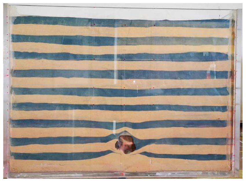
M. Ferentinou: Sinkhole collapse propagation studies through instrumented small-scale physical models                            73

Figure 3. Fiber Bragg grating system, adopted from Xu et
al. (2017).

Table 1. Scaling laws for applicable physical properties.

          Property (prototype) 1 g   Scale factor (model)
          Length                                       N
          Mass density                                 1
          Stress                                       1
          Displacement                                 N
          Strain                                       1

ing fibers for deformation measurement. The sinkhole model
was constructed inside a Perspex box, with inner dimensions
of 400 × 270 × 80 mm (length × height × width). The sink-
hole was represented through a balloon full of water. The
sinkhole collapse was induced by the deflation of a balloon,
using a controlled valve. The diameter of the balloon was
90 mm, representing a prototype of 12 × 8.1 × 2.4 m, using
a scale of 1 : 30. The prototype is representing the scenario
of a medium sinkhole 2–5 m, at medium (1–5 m) to large (5–
15 m) depth categories (Buttrick et al., 2001). For model tests
to be meaningful, similitude must be established between
stresses and strains in the model and prototype. The model        Figure 4. Failure surfaces with medium compact sand fill, the per-
is reduced by a scale factor (N) scaling laws can be used to      centages refer to balloon volume reduction (photo taken by Jean-
convert the measured properties and values of the model to        dre Labuschagne).
a full-scale prototype equivalent. Applicable scaling laws are
shown in Table 1.
   The layers of sand were placed and four optic fibre cables     3.2   Material properties
with FBGs on each optic fibre cable were placed. Twelve           The soil used for the experimental work was a silica sand
strain sensors (S1–S12) were multiplexed into 3 FBGs per fi-      known as Cullinan sand from a commercial site. The poorly
bre cable, 53 mm apart, to determine the maximum expected         graded sand was characterised as SP, and had a D50 particle
strain and strain near the boundaries of the cavity as it prop-   diameter of 0.15 mm. The sand angle of repose ws measured
agates upwards, Fig. 4. The FBG sensors were manufac-             to be 37◦ . Coloured sand was used as an indicator to enable
tured in single mode photosensitive fibre in the Photonics        simultaneously record and display internal deformation pro-
Research laboratory of the University of Johannesburg us-         cess. The sand was placed and compacted in alternating lay-
ing the phase mask technique and an Nd:YAG laser using the        ers of uncoloured sand (20 mm) and coloured sand (10 mm).
266 nm wavelength. The FBG sensors were printed to reflect
in the wavelength range between 1540 and 1555 nm.
                                                                  3.3   Testing program

                                                                  The experimental component of this project included three
                                                                  tests of reduced scaled models. The variable that was investi-
                                                                  gated was sand relative density Dr . The models we rebuild to

proc-iahs.net/382/71/2020/                                                                       Proc. IAHS, 382, 71–76, 2020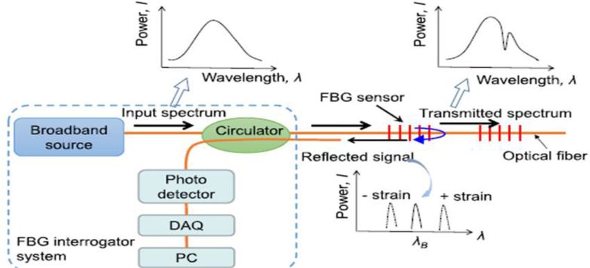
74                M. Ferentinou: Sinkhole collapse propagation studies through instrumented small-scale physical models

Figure 5. Very well compacted sand fill, at a 100 % volume reduc-
tion (photo taken by Jeandre Labuschagne).

sand relative density values of 60 %, 65 % and 95 % and den-
sities of 1560.98, 1623.41, 1705.61 kg m−3 respectively and
were tested under normal gravity (1 g). The water-inflated
balloon had a diameter of 90 mm. The deflation of the bal-
loon allowed for the upwards propagation of the sinkhole
in two-dimensional plane-strain conditions, Jacobsz (2016).
The balloon was deflated by letting water out at a flow rate of     Figure 6. Failure surfaces with compact sand fill, the percent-
34.17, 47.40 and 41.43 mL min−1 respectively. The induced           ages refer to balloon volume reduction (photo taken by Es-
movement due to the balloon deflation was 90 mm, which al-          merelda Steyn).
lowed for the visualisation of fully developed failure surfaces
within the soil mass.
                                                                    4.2   FBGs Measurement results

4     Results                                                       The analysis of the experimental results that were recorded
                                                                    by the FBGs sensors were used in order to identify a subsi-
4.1    Failure mechanism                                            dence pattern above the balloon resulting from the induced
                                                                    collapse. Each sensor array contained three gratings that
Figures 4, 5 and 6 show the failure surface that developed as
                                                                    were written along a single fiber by using UV laser. The
was observed from the Plexiglass wall for the 60 % (test 1)
                                                                    sensing length of each FBG was 6 mm. The spacing between
and 65 % (test 2) and 95 % (test 3) relative density of the
                                                                    FBGs in one fiber was specified for the collection of strain at
sand. The parameters that were used in order to describe the
                                                                    certain positions. Fiber 1, 2, 3, 4 were installed horizontally
failure surface, are the angle with horizontal (θi ), and the
                                                                    (Fig. 4).
maximum height of the failure surface measured from the
                                                                       Figures 7 and 8 present the strain variation of the sensors
base of the model (hv ) (Costa et al., 2009).
                                                                    for the two models. The results from test1 showed that
   According to the results in both tests a failure surface on
                                                                       the maximum strain was measured by sensor S4 approxi-
both sides of the balloon initiating at 6 cm from the centre
                                                                    mately 7.5 × 10⁻³ in nε at 40 % balloon volume reduction.
developed towards the middle of the model, at 10 % vol-
                                                                    S1 in fiber 1 close to the left side of the balloon measured
ume reduction and eventually propagated to the surface at
                                                                    8 × 10⁻⁴ nε. S7, S8, S9 measured 6 × 10⁻⁴ nε between 40 %
22 % reduction volume. The observed failure pattern is that
                                                                    and 80 % volume reduction. Interestingly S10, S11, S12, did
of a chimney caving with a width of 3.80 and 2.28 cm for
                                                                    not measure high strains as it would theoretically has been
test 1 and test 2 respectively. Secondary failure surfaces de-
                                                                    expected based on settlement experienced.
velopped after 30 % volume reduction from the middle of the
                                                                       The results from test 2 indicated that the maximum strain
height to the surface with an angle of 80◦ to the horizontal.
                                                                    was measured by sensor S3 approximately 6 × 10⁻⁴ nε at
The maximum settlement was 2.80 cm for test 1 and 2.28 cm
                                                                    30 % balloon volume. S6 measured 7×10⁻⁴ and S9 1×10⁻³ .
for test 2. The settlement trough width was 11.4 and 14.28 cm
                                                                    The recorded strain relates to the secondary failures. The sen-
for test 1 and test 2 respectively. The chimney width was 3.8
                                                                    sors located at the centre and the array laid at the highest
and 5.71 cm for test 1 and test 2 respectively.
                                                                    level within the model measured very low strain which does
                                                                    not verify what would be expected from the empirical ob-
                                                                    servation of surficial settlements induced by excavations of
                                                                    tunnels (Peck, 1969).

Proc. IAHS, 382, 71–76, 2020                                                                         proc-iahs.net/382/71/2020/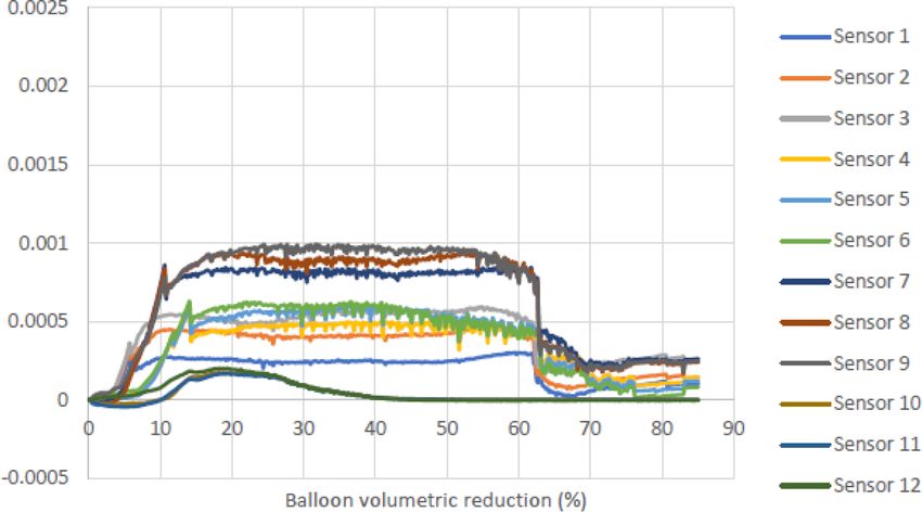
M. Ferentinou: Sinkhole collapse propagation studies through instrumented small-scale physical models                          75

Figure 7. Strain variation for of all FBGs during test 1.

Figure 8. Strain variation for of all FBGs during test 2.

5   Conclusions                                                 strains that were recorded by FBGs sensors indicated that the
                                                                highest stains were recorded at the secondary failure surfaces
The failure mechanism in a granular soil induced by the de-     that were developed starting from the sides of the balloon. A
flation of a balloon simulating an underground cavity was       complete program of experiments is planned to further in-
studied in this paper, though small-scale models. The models    vestigate the effect of relative density, and water content, in
were built with a ratio of overburden (H ) to the balloon di-   a geotechnical centrifuge facility.
ameter (D) of 4, simulating deep conditions. The following         The technique is also planned to be applied at identified pi-
conclusions can be drawn:                                       lot areas in collaboration with the local municipalities. Sites
   The mechanism involved an initial well defined vertical      that are prone to sinkhole hazard for the last thirty years or
failure surface propagating to the surface following a chim-    so, are going to serve as monitoring sites, where the current
ney caving pattern, with an evident curvature upwards. A sec-   methodoly can be fyrther implemented and tested as to pro-
ondary failure surface at 80◦ to the horizontal in the region   viding an early warning system.
above the balloon develops at almost 35 % volume reduction.
   The soil density influenced the magnitude of the surficial
settlement, which was almost 2.5 % of the balloon diameter.     Data availability. Data acquired during the project will be avail-
                                                                able through University of Johannesburg repository.
Surficial settlement was larger in less compacted sands and
did not develop at all in very well compacted sands. The max

proc-iahs.net/382/71/2020/                                                                     Proc. IAHS, 382, 71–76, 2020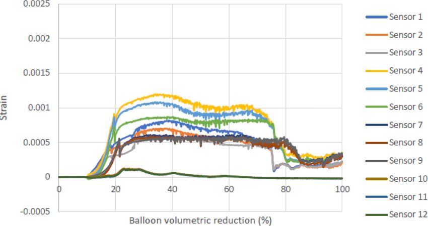
76                   M. Ferentinou: Sinkhole collapse propagation studies through instrumented small-scale physical models

Competing interests. The author declares that there is no con-           Costa, Y. D., Zornberg, J. G., Bueno, B. S., and Costa, C. L.: Failure
flict of interest.                                                          Mechanisms in Sand over a Deep Active Trapdoor, J. Geotech.
                                                                            Geoenviron., 135, 1741–1753, 2009.
                                                                         Craig, W. H.: Collapse of cohesive overburden following removal
Special issue statement. This article is part of the special is-            of support, Can. Geotech. J., 27, 355–364, 1990.
sue “TISOLS: the Tenth International Symposium On Land Sub-              Iten, M.: Novel Applications of Distributed Fiber Optic Sens-
sidence – living with subsidence”. It is a result of the Tenth Inter-       ing in Geotechnical Engineering, Doctoral thesis, DISS. ETH
national Symposium on Land Subsidence, Delft, the Netherlands,              No. 19632, ETH Zurich, Zurich, 1–33, 2011.
17–21 May 2021.                                                          Jacobsz, S. W.: Trapdoor experiments studying cavity propagation,
                                                                            in: Proceedings of the first Southern African Geotechnical Con-
                                                                            ference, 5–6 May 2016, Suncity, Taylor & Francis Group, 2016.
Acknowledgements. The author would like to acknowledge, Je-              Othonos, A.: Bragg Gratings in Optical Fibres: Fundamentals and
andre Labuschagne and Esmerelda Steyn, for conducting the exper-            Applications, Optical Fibre Sensor Technology, 79–187, Kulwar
iments as part of their research projects, at the University of Johan-      Academic Publishers, the Netherlands, 2000.
nesburg.                                                                 Peck, R. B.: State of the art report: Deep excavations and tunnelling
                                                                            in soft ground, Proc. 7th Int. Conf in Soil Mechanics and Foun-
                                                                            dation Engineering, Mexico City, 225–290, 1969.
                                                                         White, D. J. and Bolton, M. D.: Soil deformation around a dis-
Financial support. This research has been supported by the Wa-
                                                                            placement pile in sand, Physical modelling in geotechnics:
ter Research Commission in South Africa (grant no. K5 2937) and
                                                                            ICPMG’02, Newfoundland, 649–654, 2002.
the National Research Foundation (NRF) (grant no. 113371).
                                                                         Xu, D.-S., Dong, L.-J., Borana, L., and Liu, H.-B.: Early-Warning
                                                                            System With Quasi-Distributed Fiber Optic Sensor Networks and
                                                                            Cloud Computing for Soil Slopes, v5, IEEE Access, 5, 25437–
References                                                                  25444, https://doi.org/10.1109/ACCESS.2017.2771494, 2017.
                                                                         Zhang, D., Xu, Q., Bezuijen, A., Zheng, G., and Wang,
Abdulla, W. A. and Goodings, D. J.: Modeling of sinkholes in                H.: Internal deformation monitoring for centrifuge slope
  weakly cemented sand, J. Geotech. Eng., 122, 998–1005, 1996.              model with embedded FBG arrays, Landslides, 14, 407,
Augarde, C. E., Lyamin, V. A., and Sloan, S.: Prediction of                 https://doi.org/10.1007/s10346-016-0742-2, 2017.
  undrained sinkhole collapse, J. Geotech. Geoenviron., 129, 197–
  205, 2003.
Brady, B. H. and Brown, E. T.: Rock Mechanics for underground
  mining, Chaoman and Hall, London, 1993.
Buttrick, D. B., van Schalkwyk, A. R., Kleywegt, R. J., and Water-
  meyer, R. B.: Proposed method for dolomite land hazard and risk
  assessment in South Africa, J. S. Afr. Inst. Civ. Eng., 43, 27–36,
  2001.

Proc. IAHS, 382, 71–76, 2020                                                                                  proc-iahs.net/382/71/2020/
You can also read