SMA 3000 Series Master Clock - Installation Manual V9
←
→
Page content transcription
If your browser does not render page correctly, please read the page content below
Installation Manual V9

SMA 3000 Series Master Clock

                         The Sapling Company, Inc.     215.322.6063 P.
                         1633 Republic Road            215.322.8498 F.
                         Huntingdon Valley, PA 19006   www.sapling-inc.com
                         USA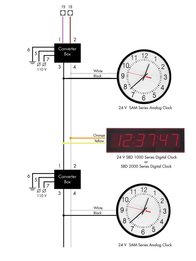
The Sapling Company, Inc.     215.322.6063 P.
                                                              1633 Republic Road            215.322.8498 F.
                                                              Huntingdon Valley, PA 19006   www.sapling-inc.com
                                                              USA

SMA 3000 Master Clock

Table of Contents

Table of Contents—2
Table of Contents—3
Wall Mount Installation —4
Rack Mount Installation —5
Installing the Master Clock with the Line Cord Receptacle—6
AC Power Wiring using 14 AWG Romex Cable—6
Rear View of Unit—7
Installing the Remote Antenna—7
Remote Antenna Mounting Instructions—8
Basic Information—9
2 Wire Digital Communication System Connection—10
RS485 Communication System Connection—11
Sync-Wire Communication System Connection—12
Once-a-day Pulse Using Clock 1 or Clock 2—13
Sync-Wire 59 Minute Correction—14
Sync-Wire 58 Minute Corrections 1–4—14
Sync-Wire National Time/Rauland Input—15
Sync-Wire Rauland Digital—15
Sync-Wire Dukane Digital—16
Sync-Wire Once a Day Pulse—16
GPS Antenna Installation—17
Setting Master Clock to GPS Mode—17
Fire Alarm Interface Installation—18
Patch Cable Installation—18
Error Codes on LED Display—19
Setting the Time from the LCD Display—20
Setting the Date from the LCD Display—20
Add Events from the LCD Screen—21
View/Edit Events Programming from the LCD Display—22
Add Schedule Change from the LCD Display (max. 100)—23
View/Edit Schedule Change from the LCD Display—24
Activate Manually from the LCD Display—24
Setting 12/24 Hour Mode from the LCD Display—25
BELL Messaging from the LCD Display—25
Numeric Messaging from the LCD Display—26
Setting the Primary Time Source—27

*manuals may change without prior notice
                                                                                                                  2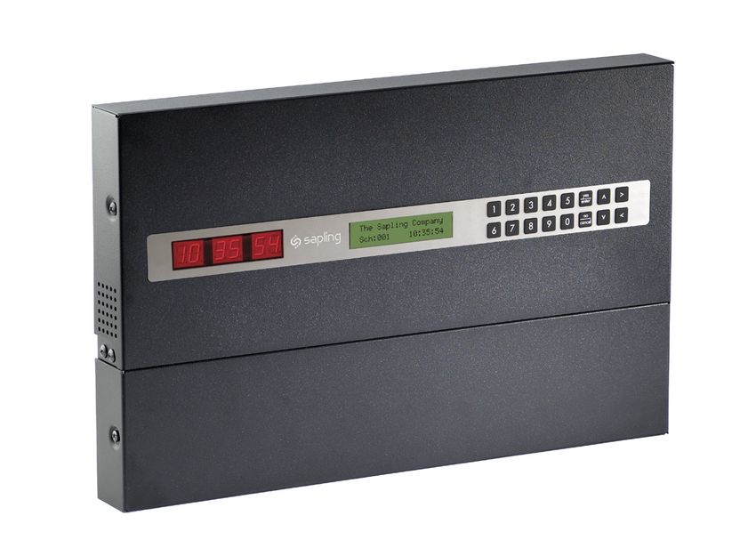
The Sapling Company, Inc.     215.322.6063 P.
                                                                            1633 Republic Road            215.322.8498 F.
                                                                            Huntingdon Valley, PA 19006   www.sapling-inc.com
                                                                            USA

SMA 3000 Master Clock

Table of Contents

Setting the Secondary Time Source—27
Sync-Wire Communication - Programming Clock 1 & 2 Circuits from the LCD Display—28
Setting Daylight Savings Time from the LCD Display—28
Sync-Wire Communication – Protocol Definitions—29
Configuring the Zone Durations from the LCD Display—30
RS485 Communication - Setting the Data Rate from the LCD Display—31
Setting the User Password from the LCD Display—31
Setting the Bias Seconds from the LCD Display—32
Setting the Time Zone Offset from the LCD Display—32
Setting or Viewing the IP Address from the LCD Display—33
Setting the Subnet Mask from the LCD Display—33
Setting the Gateway from the LCD Display—34
Setting the DNS Address from the LCD Display—34
Accessing the Web Interface (when connected via DHCP)—35
Accessing the Web Interface (when using a static IP)—35
Accessing the Web Interface (when using a crossover cable)—35
Web Interface - Log In—36
Web Interface - Date/Time—37
Web Interface - Events—38
Web Interface - Add/Edit Events (including Countdown mode)—39
Web Interface - Add/Edit Events (including Countdown mode) continued —40
Web Interface - Schedules—41
Web Interface - Schedule Change (max. 100)—42
Web Interface - Manual Control—43
Web Interface - Settings—44
Web Interface - System Settings—45
Web Interface - DST—46
Web Interface - Synchronization—47
Web Interface - IP—48
NTP Servers—49
Web Interface - IP Status—50
Web Interface - Clock Features—51
Web Interface - Database—52
Frequently Asked Questions—53
Troubleshooting—54
Compliances—55

                                                                                                                                3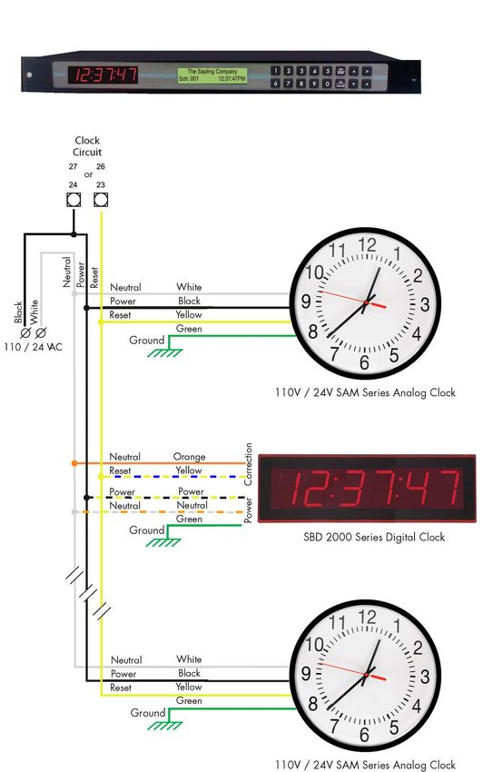
The Sapling Company, Inc.         215.322.6063 P.
                                                                                      1633 Republic Road                215.322.8498 F.
                                                                                      Huntingdon Valley, PA 19006       www.sapling-inc.com
                                                                                      USA

Wall Mount Installation

                                                                    Fig 1

1. Place the supplied template on the wall where the master clock is being mounted.
2. Mark the center point of the top right hole. Drill the hole and install the supplied anchor from the mounting kit.
3. Install the screw into the anchor and hang the template from the top right hole.
4. Using a level and the LINE on the supplied template, mark the center of the three remaining holes.
5. Remove the template and drill out the three remaining holes and insert the anchors.
6. Insert the two top screws into the anchors, leaving 1/8” of thread exposed. Unscrew the bottom wiring cover on the master clock.
7. Line up the top keyholes on the back of the master clock with the two top screws. Slide the master clock into the keyholes and then lock it into
   place.
8. Insert the two remaining bottom screws.
9. Screw the wiring cover back into its original position.

                                                                                                                                                      4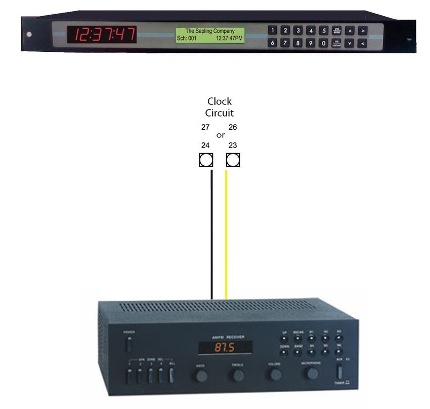
The Sapling Company, Inc.     215.322.6063 P.
                                                                                       1633 Republic Road            215.322.8498 F.
                                                                                       Huntingdon Valley, PA 19006   www.sapling-inc.com
                                                                                       USA

Rack Mount Installation

1. The master clock is 1U in size. Install the threaded nuts in the desired location in the rack rails.
2. Put the nylon washers on the two screws supplied.
3. Line up the master clock with the threaded nut.
4. Insert screws into the threaded nuts and tighten.

                                                                                                                                           5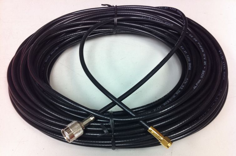
The Sapling Company, Inc.        215.322.6063 P.
                                                                                                           1633 Republic Road               215.322.8498 F.
                                                                                                           Huntingdon Valley, PA 19006      www.sapling-inc.com
                                                                                                           USA

Before You Get Started

Installing the Master Clock with the Line Cord Receptacle

*This product is intended for commercial use only and not intended for use in a private residential area

*This product is to be installed in a restricted access location by qualified service personnel only                                     Remainder of cord not shown

                                                                                                                                                               *220-240 VAC
                                                                                                                                                               Disconnect

Caution! Do not plug in the power cord until the following steps are completed.

1. The square knockout on the wiring chassis must be removed.
2. The Heyco Bushing must be attached to the power cord as shown. Use pliers to push both halves of the bushing together while they lock.
3. Put the wires through the knockout and push the bushing into the metal until it locks tightly into place. The word Heyco on the bushing faces
   up.
4. Put each wire into the supplied connector and tighten the screws. The wiring label located on the chassis will show where to connect the
   wires.
* Power disconnect and/or protection is to be provided by the installer

AC Power Wiring using 14 AWG Romex Cable

*Note: For CE Compliant installation, use minimum 0.75mm² cable or approved grounded cordset

Caution! The AC Power Source must be turned OFF.

1. Remove a round knockout on the wiring chassis, preferably one near the AC Input Connector.
2. Install a standard ½” Romex Bushing and tighten in place.
3. Pass the Romex Cable through the Bushing and clamp in place. Do Not over tighten the screws.
4. Strip back the outside cable sheathing to expose the White, Black and Ground wires.
5. Strip back the insulation on the White and Black wire ¼”.
6. Put each wire into the supplied connector and tighten the screws. The wiring label located on the wiring chassis indicates where to connect
   the wires.

                                                                                                                                                                          6
The Sapling Company, Inc.            215.322.6063 P.
                                                                                           1633 Republic Road                   215.322.8498 F.
                                                                                           Huntingdon Valley, PA 19006          www.sapling-inc.com
                                                                                           USA

Rear View of Unit

          |                                |                         |        |            |               |        |               |                       |
          |                                |                         |        |            |               |        |               |                       |
        q                                w                         e         r            t              y         u               i                       o

q    Zones 5-8 This terminal block is where connections are made for connecting zones 5-8 (when ordered)

w    Zones 1-4      This terminal block is where connections are made for connecting zones 1-4 (when ordered)

e    Clock 1 & 2 Sync-Wire Outputs             This terminal block is where connections would be landed for Clock 1 and Clock 2 sync-wire
     communication relay outputs.
r    RS485 Input/Output         This terminal block is where connections would be landed for RS485 communication to and from other Sapling
     systems.
t    Inputs This terminal block is where connections would be landed to use the SMA as a slave clock when being controlled by another
     system.
y    Remote RF Antenna (Rack Mount only)               This terminal block is where the connection to an external RF antenna would terminate.

u    Ethernet      This RJ45 jack is used for connecting the master clock to a network for programming and/or timekeeping capabilities.

i    GPS Connector        This GPS connector is where the antenna for the GPS gets mounted to (GPS option only).

o    Power Input       This power outlet is used to power up the SMA master clock.
NOTE:    This device contains a lithium battery. Replace Battery With Varta, Part No. CR2032 Only. Use Of Another Battery May Present A
         Risk Of Fire Or Explosion. Batteries can be obtained and should be installed by the manufacturer.
WARNING: Battery May Explode If Mistreated. Do Not Recharge, Disassemble Or Dispose Of In Fire.

Installing the Remote Antenna

                                                                         Blue
                                                                         Green
                                                                         Yellow
                                                                         White
                                                                         Red

Connect the Remote Antenna to the Master Clock using the supplied 25 foot, 5 conductor 18 AWG cable. Use the wiring diagram and colors as shown above.

Strip the insulation back 1/4 inch on each wire. Use a bushing in the wiring chassis to pass the cable through and secure it, then insert wires into the conductor
and tighten the screws.

For all input and output wiring use copper conductors only tightening torque for terminal block screws is 31 to 35 in/oz.

                                                                                                                                                                 7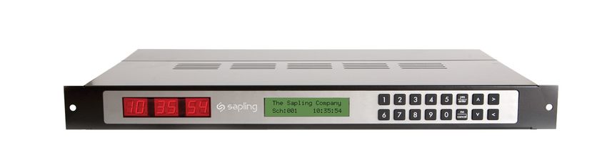
The Sapling Company, Inc.         215.322.6063 P.
                                                                                      1633 Republic Road                215.322.8498 F.
                                                                                      Huntingdon Valley, PA 19006       www.sapling-inc.com
                                                                                      USA

Remote Antenna Mounting Instructions

1. Place the supplied template on the wall where the remote antenna is being mounted.
2. Mark the center point of the top right hole. Drill the hole and install the supplied anchor from the mounting kit.
3. Install the screw into the anchor and hang the template from the top right hole.
4. Using a level and the LINE on the supplied template, mark the center of the three remaining holes.
5. Remove the template and drill out the three remaining holes and insert the anchors.
6. Insert the two top screws into the anchors, leaving 1/8” of thread exposed. Unscrew the bottom wiring cover on the remote antenna.
7. Line up the top keyholes on the back of the remote antenna with the two top screws. Slide the remote antenna into the keyholes and then lock it
   into place.
8. Insert the two remaining bottom screws.
9. Screw the wiring cover back into its original position.

                                                                                                                                                 8
The Sapling Company, Inc.         215.322.6063 P.
                                                                                   1633 Republic Road                215.322.8498 F.
                                                                                   Huntingdon Valley, PA 19006       www.sapling-inc.com
                                                                                   USA

Before You Get Started

Basic Information

Definitions
Event A pre-programmed action, such as ringing of bells at a specific time, which is triggered by a relay closure in one or more of the zones of
the master clock. Each event is assigned a schedule number.
Schedule    A series of programmed events. An example of a schedule would be a typical school day.
Zone   Each zone is controlled by a relay closure where devices such as bells can be connected.

User programming features
All 3000 series user programming is to be done by using the 16-button keypad located on the front of the Sapling master clock or via the web
interface software upgrade. The keypad is shown below:

The LCD display is 20 characters wide and consists of both a top and a bottom line. When the master is powered on, the LCD display should read:

Accessing Features from the LCD Display
To enter the user programming mode, you will need to use the four digit user password. The default password is 1111. This may or may not be
changed by the installing technician. Type in the four digit password on the keyboard. There is no need to press the YES/ENTER key after entering
the password because the master clock will go straight to user programming upon verification of the password. Please note: your password will be
hidden as you enter it. The * sign will appear instead of digits.

To Exit the Programming Mode from the LCD Display
If at any time during programming, you wish to exit programming mode, press the YES/ENTER key or the NO/CANCEL key, as appropriate, in
response to the prompts on the LCD display. After scrolling through all the options and responding to all applicable prompts, the LCD display will
then return to the main screen. There is a 20 second timeout if no buttons are pressed.

                                                                                                                                                     9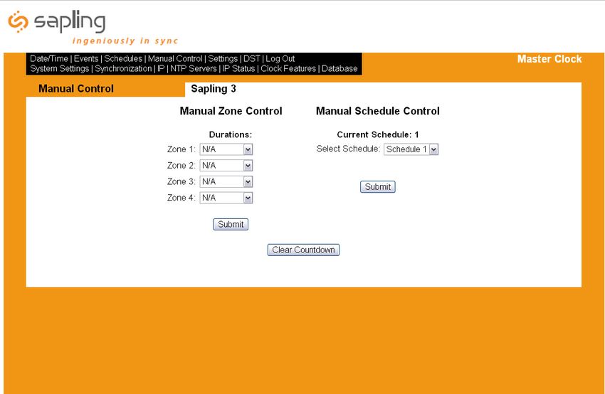
The Sapling Company, Inc.     215.322.6063 P.
                                                1633 Republic Road            215.322.8498 F.
                                                Huntingdon Valley, PA 19006   www.sapling-inc.com
                                                USA

System Connections – Wired Systems

2 Wire Digital Communication System Connection

                                18 19

                      110V              White
                    (EU 240V)           Black

                      110V
                    (EU 240V)
                                        White
                                        Black

                                                                                                    10
The Sapling Company, Inc. 215.322.6063 P.
1633 Republic Road 215.322.8498 F.
Huntingdon Valley, PA 19006 www.sapling-inc.com
USA
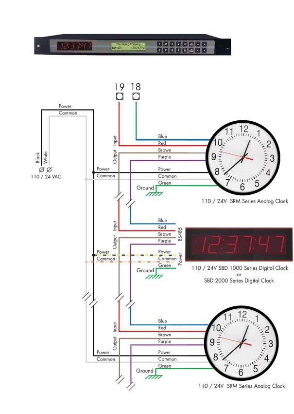
System Connections – Wired Systems
RS485 Communication System Connection
Black
White
(EU 240/24VAC)
(EU 240/24V)
Black/Yellow
White/Orange
(EU 240/24V)
Black
White
(EU 240/24V)
11The Sapling Company, Inc. 215.322.6063 P.
1633 Republic Road 215.322.8498 F.
Huntingdon Valley, PA 19006 www.sapling-inc.com
USA
System Connections – Wired Systems
Sync-Wire Communication System Connection
(EU 240/24VAC)
(EU 240/24V)
/Blue
Black/Yellow
White/Orange
(EU 240/24V)
(EU 240/24V)
12The Sapling Company, Inc. 215.322.6063 P.
1633 Republic Road 215.322.8498 F.
Huntingdon Valley, PA 19006 www.sapling-inc.com
USA
System Connections – Wired Systems
Once-a-day Pulse Using Clock 1 or Clock 2
Intercom, paging system, or other device
13The Sapling Company, Inc. 215.322.6063 P.
1633 Republic Road 215.322.8498 F.
Huntingdon Valley, PA 19006 www.sapling-inc.com
USA
Inputs – Sync-Wire Inputs Installation
Sync-Wire 59 Minute Correction
Dry Contact Closure 110VAC Interface 24VAC Interface
(EU 240VAC)
7 17 8 12 16 17 15 17
110VAC Neutral
24VAC Neutral
110VAC Hot
24VAC Hot
N.O.
COM
Sync-Wire 58 Minute Corrections 1–4
Dry Contact Closure 110VAC Interface 24VAC Interface
(EU 240VAC)
7 17 8 12 16 17 15 17
110VAC Neutral
24VAC Neutral
110VAC Hot
24VAC Hot
N.O.
COM
14The Sapling Company, Inc. 215.322.6063 P.
1633 Republic Road 215.322.8498 F.
Huntingdon Valley, PA 19006 www.sapling-inc.com
USA
Inputs – Sync-Wire Inputs Installation
Sync-Wire National Time/Rauland Input
Dry Contact Closure 110VAC Interface 24VAC Interface
(EU 240VAC)
Sync-Wire Rauland Digital
Input Output
11 17 8 24 7 23 22
+5V Out
Dig Out
15The Sapling Company, Inc. 215.322.6063 P.
1633 Republic Road 215.322.8498 F.
Huntingdon Valley, PA 19006 www.sapling-inc.com
USA
Inputs – Sync-Wire Inputs Installation
Sync-Wire Dukane Digital
Sync-Wire Once a Day Pulse
Dry Contact Closure
16The Sapling Company, Inc. 215.322.6063 P.
1633 Republic Road 215.322.8498 F.
Huntingdon Valley, PA 19006 www.sapling-inc.com
USA
Inputs – GPS Installation
GPS Antenna Installation
Supplied by Sapling: GPS Dome, a 75’ of RG58 or 150’ length of RG59 cabling (refer to Figure 1.1)
Not supplied by Sapling: Steel or PVC piping with 1”-14” thread or 3/4” pipe thread, teflon tape, mounting plate and hardware for piping (refer to
Figure 1.1)
*NOTE: Placement of antenna and height of piping needs to be on the rooftop of the building
1) Route cabling from the room in which the master clock will be located to the roof of the building, allowing the GPS dome (refer to Figure 1.1) to
have a full 180 degrees view of the sky
2) Run cabling through piping and attach the end of the cabling to the bottom of the GPS dome via TNC connection.
3) Screw GPS dome onto the top of the piping. Be careful not to twist the cable. Use teflon tape on the pipe threads to tighten seal and prevent
water damage.
4) Mount piping to the roof of the building with mounting plate and hardwear supplied by the user.
5) Connect the RG58 or 59 cabling to the GPS input located on the back of the master clock via SMA connection.
Setting Master Clock to GPS Mode
Programming through SMA 3000 pushbuttons - Refer to page 27 for setting your master clock’s time source to GPS from the LCD display.
Programming through the Web Interface - Refer to page 47 for setting your master clock’s time source to GPS from the web interface.
Fig 1.1
GPS Dome
TNC Connection
Piping
SMA Connection
Mounting Plate
17The Sapling Company, Inc. 215.322.6063 P.
1633 Republic Road 215.322.8498 F.
Huntingdon Valley, PA 19006 www.sapling-inc.com
USA
Fire Alarm Interface Installation / Patch Cable Installation
Fire Alarm Interface Installation
The Fire Alarm Interface allows a relay closure to be connected to the SMA master clock that allows the user to interface the existing fire alarm
with the Sapling SBD 1000 or SBD 2000 series digital clocks.
7 10 8 9
N.O.
COM
When a relay closure occurs on pins 8 and 9, “FirE” will display on the digital slave clocks connected using RS485 or two wire digital
communication.
Patch Cable Installation
Wall Jack to
Network
Fig 1.1
1) Connect a patch cable to the RJ45 port on the SMA Master Clock as shown in Fig 1.1.
2) Connect the other end of the patch cable to an Ethernet jack connected to the network.
18The Sapling Company, Inc. 215.322.6063 P.
1633 Republic Road 215.322.8498 F.
Huntingdon Valley, PA 19006 www.sapling-inc.com
USA
Error Codes
Error Codes on LED Display
When one of the following errors occurs, one of the LED lights located above one of the six characters on the LED display will begin to flash. See figure below
indicating the error each flashing light is associated with.
__________ PM active
|
| _________ Ethernet disconnected
| |
| | ______ GPS error
| | |
| | | _____ DHCP error
| | | |
| | | | ___ SNTP error
| | | | |
| | | | | _unused
| | | | | |
.. .. ..
19The Sapling Company, Inc. 215.322.6063 P.
1633 Republic Road 215.322.8498 F.
Huntingdon Valley, PA 19006 www.sapling-inc.com
USA
User Level Programming
Setting the Time from the LCD Display
1) Type in the user level password (default is 1111) at the main screen to enter user level programming.
2) The display should read “Set Time?”, as displayed in Fig 2.1.
3) Press the YES/ENTER button.
4) Enter the time (in 24 hour mode) using the keypad. When completed, press the YES/ENTER button to confirm the selection.
5) To exit and return to the main screen, continue to press the NO/CANCEL button until the main screen appears.
Fig 2.1
Setting the Date from the LCD Display
1) Type in the user level password (default is 1111) at the main screen to enter user level programming.
2) Press the NO/CANCEL button until the display reads “Set Date” as shown in Fig 2.2.
3) Press the YES/ENTER button.
3) Type in the desired date using the MM/DD/YYYY format.
4) Press the YES/ENTER button to confirm the date.
5) To exit and return to the main screen, continue to press the NO/CANCEL button until the main screen appears.
Fig 2.2
20The Sapling Company, Inc. 215.322.6063 P.
1633 Republic Road 215.322.8498 F.
Huntingdon Valley, PA 19006 www.sapling-inc.com
USA
User Level Programming
Add Events from the LCD Screen
1) Type in the user level password (default is 1111) at the main screen to enter user level programming.
2) Press the NO/CANCEL button until the display reads “Add Events?” as shown in Fig 2.3.
Fig 2.3
3) Press the YES/ENTER button to enter the event programming for the event.
4) The display should look similar to Fig 2.4.
Fig 2.4
5) Type the three digit schedule number that the event should occur on.
6) Type the time that the event is to occur in 24 hour format.
7) Select the day(s) of the week that event is to occur on by using the ← and → keys and then pressing the YES/ENTER button to toggle each day.
The day will capitalize to confirm the selection. (MF = Monday through Friday and ED = Everyday).
8) Press the ↓ key to go to the second screen. The display should look similar to Fig 2.5.
Fig 2.5
9) Use the ← and → buttons to scroll through each zone that the event is to occur. To scroll through the durations, continue to press the YES/
ENTER button until the desired duration is set. The durations are:
N/A = Not Applicable (does nothing to the zone) Dur 5* = Set the Relay to Close for Five Seconds
Always_Off = Turns the Relay Off CStart** = Count Down Start
Always_On = Turns the Relay On CStop**= Count Down Stop
Dur 3* = Set the Relay to Close for Three Seconds
10) Press the ↓ button to confirm. The display should look similar to Fig 2.6. Press the YES/ENTER button to confirm the event.
Fig 2.6
11) To continue adding events, follow steps 5 through 10.
12) To exit and return to the main screen, continue to press the NO/CANCEL button until the main screen appears.
* - Zone durations are configurable. See page 30 for details.
** - These options are only available if the countdown option is ordered.
21The Sapling Company, Inc. 215.322.6063 P.
1633 Republic Road 215.322.8498 F.
Huntingdon Valley, PA 19006 www.sapling-inc.com
USA
User Level Programming
View/Edit Events Programming from the LCD Display
1) Type in the user level password (default is 1111) at the main screen to enter user level programming.
2) Press the NO/CANCEL button until the display reads “View/Edit Events?” as shown in Fig 2.7.
Fig 2.7
3) Press the YES/ENTER button.
4) The first event will scroll across the top line of the LCD display as shown in Fig 2.8. Press the YES/ENTER button to edit the event.
Fig 2.8
5) To edit the event, follow the steps on page 21, steps 3-10.
6) To view the events, use the ↓ button to scroll between each event.
7) To exit and return to the main screen, continue to press the NO/CANCEL button until the main screen appears.
22The Sapling Company, Inc. 215.322.6063 P.
1633 Republic Road 215.322.8498 F.
Huntingdon Valley, PA 19006 www.sapling-inc.com
USA
User Level Programming
Add Schedule Change from the LCD Display (max. 100)
1) Type in the user level password (default is 1111) at the main screen to enter user level programming.
2) Press the NO/CANCEL button until the display reads “Add Schedule Change?” as shown in Fig 2.9.
Fig 2.9
3) Press the YES/ENTER button.
4) Enter the schedule number that the master clock is to go to when the schedule change occurs. Then press the YES/ENTER button. See Fig 2.10.
Fig 2.10
5) Enter the date (mm/dd/yyyy) that the schedule change is to occur on as shown in Fig 2.11. Then press the YES/ENTER button.
Fig 2.11
6) Enter the time, in 24 hour mode, that the schedule change should occur at as shown in Fig 2.12. Then press the YES/ENTER button.
Fig 2.12
7) Press the YES/ENTER button to confirm the schedule change. See Fig 2.13.
Fig 2.13
8) To exit and return to the main screen, continue to press the NO/CANCEL button until the main screen appears.
23The Sapling Company, Inc. 215.322.6063 P.
1633 Republic Road 215.322.8498 F.
Huntingdon Valley, PA 19006 www.sapling-inc.com
USA
User Level Programming
View/Edit Schedule Change from the LCD Display
1) Type in the user level password (default is 1111) at the main screen tot enter user level programming.
2) Press the NO/CANCEL button until the display reads “View/Edit Schedule Change?” as shown in Fig 2.14.
Fig 2.14
3) The first schedule change will scroll across the top line of the LCD display as shown in Fig 2.15. Press the YES/ENTER button to edit the schedule
change.
Fig 2.15
4) To edit the schedule change, follow the steps on page 23.
5) To view the schedule changes, use the ↓ button to scroll between each one.
6) To exit and return to the main screen, continue to press the NO/CANCEL button until the main screen appears.
Activate Manually from the LCD Display
1) Type in the user level password (default is 1111) at the main screen to enter user level programming.
2) Press the NO/CANCEL button until the display reads “Activate Manually?” as shown in Fig 2.16.
Fig 2.16
3) Press the YES/ENTER button.
4) The display should look similar to Fig 2.17. To scroll through the zones, use the ↑ and ↓ buttons. To change the duration for a specific zone, use
the → button to change the setting.
Fig 2.17
5) To confirm the selection, press the YES/ENTER buttons. See Fig 2.18.
Fig 2.18
6) To exit and return to the main screen, continue to press the NO/CANCEL button until the main screen appears.
24The Sapling Company, Inc. 215.322.6063 P.
1633 Republic Road 215.322.8498 F.
Huntingdon Valley, PA 19006 www.sapling-inc.com
USA
User Level Programming
Setting 12/24 Hour Mode from the LCD Display
1) Type in the user level password (default is 1111) at the main screen to enter user level programming.
2) Press the NO/CANCEL button until the screen shows “Set 12/24 Hour Mode?” as shown in Fig 2.19.
Fig 2.19
3) Press the YES/ENTER button to enter the option.
4) Use the ↑ and ↓ buttons to scroll between “12 Hour Mode” and “24 Hour Mode”.
5) Press the YES/ENTER button to confirm your selection.
6) To exit and return to the main screen, continue to press the NO/CANCEL button until the main screen appears.
BELL Messaging from the LCD Display
1) Type in the user level password (default is 1111) at the main screen to enter user level programming.
2) Press the NO/CANCEL button until the display reads “BELL Messaging?” as shown in Fig 2.20.
Fig 2.20
3) Press the YES/ENTER button to enter the next screen. The display should read “Zone:01 BELL: On” as shown in Fig 2.21.
Fig 2.21
4) Use the ↑ and ↓ buttons to scroll through each zone.
5) Press the → button to alternate the BELL function on and off.
6) Repeat steps 4 and 5, as desired, for each zone.
7) Press the YES/ENTER button when finished.
8) To exit and return to the main screen, continue to press the NO/CANCEL button until the main screen appears.
25The Sapling Company, Inc. 215.322.6063 P.
1633 Republic Road 215.322.8498 F.
Huntingdon Valley, PA 19006 www.sapling-inc.com
USA
User Level Programming
Numeric Messaging from the LCD Display
1) Type in the user level password (default is 1111) at the main screen to enter user level programming.
2) Press the NO/CANCEL button until the display reads “Send Number Message?” as shown in Fig 2.22.
Fig 2.22
3) Press the YES/ENTER button to enter the next screen. The display should read “Enter Clock #?” as shown in Fig 2.23.
Fig 2.23
4) Press the YES/ENTER button to enter the next screen. Enter the clock number as shown in Fig 2.24.
Fig 2.24
5) Press the YES/ENTER button. The display should read “Zone: 00” as shown in Fig 2.25. Enter the zone number.
Fig 2.25
6) Press the YES/ENTER button to enter the next screen. The display should read “Message:0000” as shown in Fig 2.26.
Fig 2.26
7) Press the YES/ENTER button to confirm the selection.
8) To exit and return to the main screen, continue to press the NO/CANCEL button until the main screen appears.
26The Sapling Company, Inc. 215.322.6063 P.
1633 Republic Road 215.322.8498 F.
Huntingdon Valley, PA 19006 www.sapling-inc.com
USA
Technician Level Programming
Setting the Primary Time Source
1) Type in 6063 at the main screen to enter the technician level menu mode.
2) Press the NO/CANCEL button until the display reads “Set Pri Time Source?” as shown in Fig 3.1.
3) Press the YES/ENTER button.
4) Use the ↑ and ↓ to scroll between all of the inputs. When the display reads the desired input, press the YES/ENTER button to confirm the selec-
tion. The supported input selections are displayed in Fig 3.2.
5) To exit and return to the main screen, continue to press the NO/CANCEL button until the main screen appears.
Fig 3.1
Real Time Clock National Time/Rauland*
RS485 59 Minute Correction*
GPS 58 Minute Correction_1*
Once a Day Pulse* 58 Minute Correction_2*
Wireless Repeater 58 Minute Correction_3*
Rauland Digital 58 Minute Correction_4*
Dukane SNTP
Fig 3.2
Setting the Secondary Time Source
1) Type in 6063 at the main screen to enter the technician level menu mode.
2) Press the NO/CANCEL button until the display reads “Set Sec Time Source?” as shown in Fig 3.3.
3) Press the YES/ENTER button.
4) Use the ↑ and ↓ to scroll between all of the inputs. When the display reads the desired input, press the YES/ENTER button to confirm the selec-
tion. The supported input selections are displayed in Fig 3.4.
5) To exit and return to the main screen, continue to press the NO/CANCEL button until the main screen appears.
Fig 3.3
Real Time Clock National Time/Rauland*
RS485 59 Minute Correction*
GPS 58 Minute Correction_1*
Once a Day Pulse* 58 Minute Correction_2*
Wireless Repeater 58 Minute Correction_3*
Rauland Digital 58 Minute Correction_4*
Dukane SNTP
Fig 3.4
* For protocol definitions, see page 29
27The Sapling Company, Inc. 215.322.6063 P.
1633 Republic Road 215.322.8498 F.
Huntingdon Valley, PA 19006 www.sapling-inc.com
USA
Technician Level Programming
Sync-Wire Communication - Programming Clock 1 & 2 Circuits from the LCD Display
1) Type in 6063 at the main screen to enter the technician level menu mode.
2) Press the NO/CANCEL button until the screen shows “Change Clock 1 Circuit Selection?” as shown in Fig 3.5.
3) Press the YES/ENTER button.
4) Press the ↑ and ↓ buttons to scroll through each protocol. The protocols are shown in Fig 3.6.
5) When the desired protocol is selected, press the YES/ENTER button to confirm the selection.
6) Press the NO/CANCEL button to get back to the screen shown in Fig 3.5.
7) Press the NO/CANCEL button again to show “Change Clock 2 Circuit Selection?”.
8) Repeat steps 3 - 5.
9) To exit and return to the main screen, continue to press the NO/CANCEL button until the main screen appears.
Fig 3.5
58 Minute Correction (1)* 59 Minute Correction*
58 Minute Correction (2)* National Time/Rauland 1*
58 Minute Correction (3)* National Time/Rauland 2*
58 Minute Correction (4)* Once a Day Pulse*
Fig 3.6
* For protocol definitions, see page 29WW
Setting Daylight Savings Time from the LCD Display
1) Type in 6063 at the main screen to enter the technician level menu mode.
2) Press the NO/CANCEL button until the screen shows “Set Daylight Savings Time?” as shown in Fig 3.7.
Fig 3.7
3) Press the YES/ENTER button.
4) Using the ↑ and ↓ buttons, scroll through “On” and “Off” as shown in Fig 3.8. For custom DST configurations, please use the web interface.
Fig 3.8
5) Press the YES/ENTER button to confirm the selection.
6) To exit and return to the main screen, continue to press the NO/CANCEL button until the main screen appears.
28The Sapling Company, Inc. 215.322.6063 P.
1633 Republic Road 215.322.8498 F.
Huntingdon Valley, PA 19006 www.sapling-inc.com
USA
System Connections – Wired Systems
Sync-Wire Communication – Protocol Definitions
1 - 58th minute (1) The hourly correction for 55 seconds every hour from XX:58:05 to XX:59:00. The daily correction (5 a.m. & 5 p.m.) is
ten correction cycles sent to the relay (each for 95 seconds) beginning at 5:05:00, 5:07:00, 5:09:00, 5:11:00, 5:13:00,
5:15:00, 5:17:00, 5:19:00, 5:21:00, and 5:23:00.
2 - 58th minute (2) The hourly correction for 60 seconds every hour from XX:58:00 to XX:59:00. The daily correction (5 a.m. & 5 p.m.) is
twelve correction cycles sent to the relay (each for 65 seconds on and 25 seconds off) beginning at 5:05:00 to 5:22:35.
3 - 58th minute (3) The hourly correction for 60 seconds every hour from XX:58:00 to XX:59:00. The daily correction (5 a.m. & 5 p.m.) is twelve
correction cycles sent to the relay (each for one minute on and two minutes off) beginning at 5:06:00.
4 - 58th minute (4) The hourly correction for 55 seconds every hour from xx:58:05 to XX:59:00. The daily correction (5 a.m. & 5 p.m.) is 12
correction cycles for 55 seconds. The timings will be 05:03:05, 05:07:05, 05:11:05, 05:15:05, 05:19:05, 05:23:05, 05:27:05,
05:31:05, 05:35:05, 05:39:05, 05:43:05 and 05:47:05.
5 - 59th minute The hourly correction for 8 seconds every hour from XX:57:54 to XX:58:02. The daily correction (5 a.m. & 5 p.m.) is a 14
second pulse from 5:57:54 to 5:58:08.
6 - National Time & Rauland (1) The hourly correction is for 25 seconds every hour from XX:00:00 to XX:00:25. The daily correction (6 a.m. & 6
p.m.) is 25 seconds on, 35 seconds off every minute for 24 minutes.
7 - National Time & Rauland (2) The hourly correction is for 25 seconds every hour from XX:00:00 to XX:00:25. The daily correction is a 24
minute pulse from 6:00:25 to 6:24:25 AM and PM.
8 - Once a Day Pulse The Once a Day Pulse allows the user to manually configure when the relay will close and for how long it needs to close
for.
9 - Rauland Digital The Rauland Digital will reset the clock to 12:00:00AM and advance the clock one minute for every 0.5 seconds that the
Dig line is shorted to ground.
29The Sapling Company, Inc. 215.322.6063 P.
1633 Republic Road 215.322.8498 F.
Huntingdon Valley, PA 19006 www.sapling-inc.com
USA
Technician Level Programming
Configuring the Zone Durations from the LCD Display
Each zone (relay) has two configurable durations that can be used during the programming of events. The default durations are three
and five seconds.
1) Type in 6063 at the main screen to enter the technician level menu mode.
2) Press the NO/CANCEL button until the screen shows “Set Zone Durations?” as shown in Fig 3.9.
Fig 3.9
3) Press the YES/ENTER button.
4) Using the ↑ and ↓ buttons, scroll through each zone number and duration until the desired option is selected as shown in Fig 3.10.
Fig 3.10
5) Press the YES/ENTER button.
6) Using the keypad, type in the new duration for the selected zone between 0001 - 3600 seconds as shown in Fig 3.11.
Fig 3.11
7) Press the YES/ENTER button to confirm the selection.
8) Repeat steps 4 - 7 for additional duration changes.
9) To exit and return to the main screen, continue to press the NO/CANCEL button until the main screen appears.
30The Sapling Company, Inc. 215.322.6063 P.
1633 Republic Road 215.322.8498 F.
Huntingdon Valley, PA 19006 www.sapling-inc.com
USA
Technician Level Programming
RS485 Communication - Setting the Data Rate from the LCD Display
1) Type in 6063 at the main screen to enter the technician level menu mode.
2) Press the NO/CANCEL button until the display reads “Set the RS485 Rate” as shown in Fig 3.12.
3) Press the YES/ENTER button.
4) Enter the duration, in seconds, that the RS485 is to send communication.
5) Press the YES/ENTER button to confirm the selection.
6) To exit and return to the main screen, continue to press the NO/CANCEL button until the main screen appears.
Fig 3.12
Setting the User Password from the LCD Display
1) Type in 6063 at the main screen to enter the technician level menu mode.
2) Press the NO/CANCEL button until the screen shows “Set the User Password?” as shown in Fig 3.13.
Fig 3.13
3) Press the YES/ENTER button. The display should look similar to Fig 3.14.
Fig 3.14
4) Type in the new four digit password.
5) Press the YES/ENTER button.
6) To exit and return to the main screen, continue to press the NO/CANCEL button until the main screen appears.
31The Sapling Company, Inc. 215.322.6063 P.
1633 Republic Road 215.322.8498 F.
Huntingdon Valley, PA 19006 www.sapling-inc.com
USA
Technician Level Programming
Setting the Bias Seconds from the LCD Display
The bias seconds allows the user to offset how many seconds, plus or minus, the time will be when receiving an input. This field can range
between plus or minus 0-9999 seconds.
1) Type in 6063 at the main screen to enter the technician level menu mode.
2) Press the NO/CANCEL button until the screen shows “Set Bias Seconds?” as shown in Fig 3.15.
Fig 3.15
3) Press the YES/ENTER button.
4) Set the bias seconds using the keypad between 0000 - 9999 seconds as shown in Fig 3.16. Use the ↑ and ↓ buttons to select positive or negative
biasing.
Fig 3.16
5) Press the YES/ENTER button.
6) To exit and return to the main screen, continue to press the NO/CANCEL button until the main screen appears.
Setting the Time Zone Offset from the LCD Display
The time zone offset will allow the time zone to be offset when a (S)NTP or GPS connection is present. For a list of typical offsets, see Fig 4.1 on
page 45.
1) Type in 6063 at the main screen to enter the technician level menu mode.
2) Press the NO/CANCEL button until the screen shows “Set Time Zone Offset?” as shown in Fig 3.17.
Fig 3.17
3) Press the YES/ENTER button.
4) Using the ↑ and ↓ buttons to select the positive or negative offset, then enter the time zone using the keypad as shown Fig 3.18. The default it -5.
Fig 3.18
5) When the desired offset is chosen, press the YES/ENTER button to confirm the selection.
6) To exit and return to the main screen, continue to press the NO/CANCEL button until the main screen appears.
32The Sapling Company, Inc. 215.322.6063 P.
1633 Republic Road 215.322.8498 F.
Huntingdon Valley, PA 19006 www.sapling-inc.com
USA
Technician Level Programming
Setting or Viewing the IP Address from the LCD Display
1) Type in 6063 at the main screen to enter the technician level menu mode.
2) Press the NO/CANCEL button until the display reads “Set IP Address?” as shown in Fig 3.19.
3) Press the YES/ENTER button.
4) Type in the 12 digit IP address using the keypad. (e.g. 192.168.000.012) Setting the IP address to 000.000.000.000 automatically sets the unit
for DHCP enabled. Any other value disables DHCP and considers it a static IP.
5) To exit and return to the main screen, continue to press the NO/CANCEL button until the main screen appears.
Fig 3.19
Note: If DHCP is enabled and is functioning, the displayed IP address will be the address of the unit which was assigned by the router. The master clock must be power
cycled for network parameter changes to take effect.
Setting the Subnet Mask from the LCD Display
1) Type in 6063 at the main screen to enter the technician level menu mode.
2) Press the NO/CANCEL button until the display reads “Set Subnet Mask?” as shown in Fig 3.20.
3) Press the YES/ENTER button.
4) Type in the 12 digit gateway address using the keypad. (e.g. 255.255.255.000)
5) To exit and return to the main screen, continue to press the NO/CANCEL button until the main screen appears.
Fig 3.20
Note: If DHCP is enabled, then the router will likely overwrite this value. The unit must be power cycled for these changes to take effect.
33The Sapling Company, Inc. 215.322.6063 P.
1633 Republic Road 215.322.8498 F.
Huntingdon Valley, PA 19006 www.sapling-inc.com
USA
Technician Level Programming
Setting the Gateway from the LCD Display
1) Type in 6063 at the main screen to enter the technician level menu mode.
2) Press the NO/CANCEL button until the display reads “Set Gateway Address?” as shown in Fig 3.21.
3) Press the YES/ENTER button.
4) Type in the 12 digit gateway address using the keypad. (e.g. 192.168.000.001)
5) To exit and return to the main screen, continue to press the NO/CANCEL button until the main screen appears.
Fig 3.21
Note: If DHCP is enabled, then the router will likely overwrite this value. The unit must be power cycled for these changes to take effect.
Setting the DNS Address from the LCD Display
1) Type in 6063 at the main screen to enter the technician level menu mode.
2) Press the NO/CANCEL button until the display reads “Set DNS Address?” as shown in Fig 3.22.
3) Press the YES/ENTER button.
4) Type in the 12 digit gateway address using the keypad. (e.g. 192.168.000.001)
5) To exit and return to the main screen, continue to press the NO/CANCEL button until the main screen appears.
Fig 3.22
Note: If DHCP is enabled, then the router will likely overwrite this value. The unit must be power cycled for these changes to take effect.
34The Sapling Company, Inc. 215.322.6063 P.
1633 Republic Road 215.322.8498 F.
Huntingdon Valley, PA 19006 www.sapling-inc.com
USA
Web Interface Programming
*The web interface is an optional feature and is not available on all units.
*Please make sure that ports 123 and 80 in both directions are open on the firewall.
Accessing the Web Interface (when connected via DHCP)
1) Plug in a patch cable to the unit, and then into a switch on your network.
2) Press the “9” and the “1” key simultaneously.
3) The IP address will display on the bottom line for about three to five seconds.
4) When finished viewing, press the NO/CANCEL button twice to get back to the main screen.
5) Open a web browser such as Internet Explorer or Firefox on a PC that’s connected to the network.
6) In the address bar, type in the IP address and press Enter. This will access the log-in screen.
Accessing the Web Interface (when using a static IP)
1) Plug in a patch cable to the unit, and then into a switch on your network.
2) Following the instructions on page 33, enter the IP address.
3) Open a web browser such as Internet Explorer or FireFox on a PC that’s connected to the network.
4) In the address bar, type in the IP address and press Enter. This will access the log-in screen.
Accessing the Web Interface (when using a crossover cable)
1) If you are accessing this on a laptop, turn off any wireless connections.
2) Click the “Start” button on the taskbar, then click on “Control Panel”.
3) Double Click on “Network Connections”.
4) Click the right mouse button on “Local Area Connection” and click “Properties”.
5) Scroll to the bottom of the connections list and single click on “Internet Protocol (TCP/IP)”.
6) Click on “Properties”.
7) Under the General tab, click the radio button that says “Use the following IP address”.
8) Enter the IP address of “192.168.0.122”.
9) Set the subnet mask to “255.255.255.0”.
10) Press 1111 on the keypad, then press the 6 and 3 key together simultaneously. The display will show, “sure enter crossover”. Press YES/ENTER.
11) Power cycle the master clock.
12) Open a web browser such as Internet Explorer or FireFox on a PC that’s connected to the network.
13) In the address bar, type in the IP address (192.168.0.123) and press Enter. This will access the log-in screen.
35The Sapling Company, Inc. 215.322.6063 P.
1633 Republic Road 215.322.8498 F.
Huntingdon Valley, PA 19006 www.sapling-inc.com
USA
Web Interface Programming
Web Interface - Log In
q
w e
q Password There are two levels of passwords that will enable the user to access features. The first level is the user level programming that
includes features like setting the time, date, adding and editing events and schedule changes. The default password for the user level is 1111.
It can be changed in the technician level. The technician level password is 6063 and gives you full access to all of the enabled features of the
master clock.
w Log In This button, when pressed, will attempt to log in to the master clock with the password that was entered in the field above.
e Forgot Password This button, when pressed, will direct you to the tech support phone number.
After five minutes of inactivity once logged in, the master clock will automatically log the user out.
36The Sapling Company, Inc. 215.322.6063 P.
1633 Republic Road 215.322.8498 F.
Huntingdon Valley, PA 19006 www.sapling-inc.com
USA
Web Interface Programming
Web Interface - Date/Time
q
w
e
q Time This field is where the current time is displayed. The time can be edited by clicking within the field, and typing in the desired time. The
time must be entered in 24 hour format (HH:MM:SS). After typing in the desired time, click the Submit button to set the time on the unit (if
there is no input connected).
w Date This field is where the current date is displayed. The date can be edited by clicking within the field, and typing in the desired date. The
date must be entered in mm/dd/yyyy format. After typing in the desired time, click the Submit button to set the date on the unit (if there is no
input connected).
e Log Out This button, when pressed, will log the user out of the browser interface.
37The Sapling Company, Inc. 215.322.6063 P.
1633 Republic Road 215.322.8498 F.
Huntingdon Valley, PA 19006 www.sapling-inc.com
USA
Web Interface Programming
Web Interface - Events
q
w
e
r
q Event List The list will display each event programmed in the master clock. It is sorted by schedule number and then by time. The Edit
button on the right, when clicked, will bring the user back to the Add Scheduled Event screen with the existing data already entered in. This
list will display ten events per page.
w Go To Events This button, when pressed, will direct the user to the selected schedule’s event list.
e Add New Event This button, when pressed, will direct the user to the Add Scheduled Event screen and will allow the user to enter a new
event.
r Back/Next These buttons, when pressed, will advance or go back to the next or previous list of ten events for viewing or editing purposes.
38The Sapling Company, Inc. 215.322.6063 P.
1633 Republic Road 215.322.8498 F.
Huntingdon Valley, PA 19006 www.sapling-inc.com
USA
Web Interface Programming
Web Interface - Add/Edit Events (including Countdown mode)
q
e
w
r
t y u
i
q Schedule This field is where the user will enter which schedule they want the event to occur on.
w Time These fields are where the user will enter the time in hour, minutes and seconds that the event is to occur.
e Days These checkboxes, when checked, will determine what days of the week the event will occur on (at least one must be selected).
r Zone Duration/Countdown These drop-down lists determine what duration the selected zone (relay) will close for, if any. There are five
options:
Option Description Miscellaneous Notes
N/A Not Applicable An event can not have all zones set this way.
On The zone (relay) will turn on.
Off The zone (relay) will turn off.
Configured Duration 1 The zone (relay) will turn on for the configured
duration which is set in the feature settings. Ranges from 1 - 3600 seconds.
Configured Duration 2 The zone (relay) will turn on for the configured
duration which is set in the feature settings. Ranges from 1 - 3600 seconds.
*CStart Starts the countdown feature. Countdown has an 18 hour time limit and cannot
proceed past midnight.
*CStop Stops the countdown feature. Countdown has an 18 hour time limit and cannot
proceed past midnight.
* This feature provides the Sapling digital clocks with the ability to count down from a preset amount of time. Simply enter a event with a CStart to start the timer and a
event with a CStop to stop the timer. The master clock will automatically calculate the difference in time between the CStart and CStop and will start counting down. There
must be an event with a CStart and an event with a CStop in order for this to function.
39The Sapling Company, Inc. 215.322.6063 P.
1633 Republic Road 215.322.8498 F.
Huntingdon Valley, PA 19006 www.sapling-inc.com
USA
Web Interface Programming
Web Interface - Add/Edit Events (including Countdown mode) continued
q
e
w
r
t y u
i
t Submit and Continue This button, when pressed, will save the current event and will display a new add event screen that has the previous
event’s information already stored in the fields.
y Submit and Finish This button, when pressed, will save the current event and then go back to the main menu.
u Erase This button, when pressed, will erase the current event.
i Event List This button, when pressed, will take the user back to the event list.
40The Sapling Company, Inc. 215.322.6063 P.
1633 Republic Road 215.322.8498 F.
Huntingdon Valley, PA 19006 www.sapling-inc.com
USA
Web Interface Programming
Web Interface - Schedules
q
w
q Schedule Change List This list displays and allows the user to edit a previously entered schedule change. The Edit button, when pressed,
will bring the user back to the Add Schedule Change screen with the existing data already filled in.
w Add New Schedule Change This button, when pressed, will bring the user to the Add Schedule Change screen.
41The Sapling Company, Inc. 215.322.6063 P.
1633 Republic Road 215.322.8498 F.
Huntingdon Valley, PA 19006 www.sapling-inc.com
USA
Web Interface Programming
Web Interface - Schedule Change (max. 100)
q
w
e
r t y
u
q Schedule This field is where the user will enter which schedule they want the master clock to change to.
w Date This field is where the user will enter which date they want the schedule change to occur.
e Time These fields will determine what time the schedule change will occur.
r Submit This button, when pressed, will save the proposed schedule change.
t Erase This button, when pressed, will erase the displayed schedule change.
y Cancel This button, when pressed, will clear out the fields and not save any of the information.
u List This button, when pressed, will go back to the schedule change list.
42The Sapling Company, Inc. 215.322.6063 P.
1633 Republic Road 215.322.8498 F.
Huntingdon Valley, PA 19006 www.sapling-inc.com
USA
Web Interface Programming
Web Interface - Manual Control
e
q
r
w
t
q Zone Durations These drop-down lists determine what duration the selected zone (relay) will close for, if any. There are five options: N/A,
On, Off, Configured Duration 1 and Configured Duration 2. Configured durations 1 & 2 can be set in the Clock Features pages.
If the user wishes for the relay to go back to its normal state, they must set the zone back to off, submit it, and then set the zone to N/A, and
submit it again.
w Submit This button, when pressed, will submit the selected duration to the designated relay.
e Select Schedule This drop-down list contains all of the schedules that are currently programmed. When the desired schedule is selected
and submitted, the clock will immediately change to the designated schedule.
r Submit This button, when pressed, will submit the schedule change.
t Clear Countdown This button, when pressed, will clear any countdowns occurring on the digital clocks.
43The Sapling Company, Inc. 215.322.6063 P.
1633 Republic Road 215.322.8498 F.
Huntingdon Valley, PA 19006 www.sapling-inc.com
USA
Web Interface Programming
Web Interface - Settings
q
w
e
r
t
t
yy
u
q Send Number This field allows the user to designate which number will be sent to the corresponding digital slave clocks. It can be up to
four numeric digits.
w Send Number to All Clocks This checkbox, when checked, will send the value in the Send Number box to all of the digital slave clocks,
regardless of zone or clock number when the Submit button is clicked.
e Clock Number This field allows the user to enter the specific clock number to send the numeric message to. This is only applicable when
using the SBD 2000 as a slave clock.
r Zone Number This field allows the user to enter the zone number to send the numeric message to. This is only applicable when using the
SBD 2000 as a slave clock.
t Set Bell Indicator The checkboxes, when checked, will display BELL on the digital slave clock displays. When a zone is selected, every time
the relay closes, the message BELL will be sent to the digital slave clocks via 2 wire digital communication or RS485.
y Submit This button, when clicked, will submit all information that has been selected.
44The Sapling Company, Inc. 215.322.6063 P.
1633 Republic Road 215.322.8498 F.
Huntingdon Valley, PA 19006 www.sapling-inc.com
USA
Web Interface Programming
Web Interface - System Settings
w
q
e
r
t y
q User Password This field allows the user to enter a new password for the user level programming. The password must be entered twice
before being changed. The default is 1111.
w RS485 Data Rate These fields allow the user to set how often RS485 will be transmitted from the master clock.
e Bias Seconds This field allows the user to offset how many seconds off, plus or minus, the time will be when receiving an input. This field
can range between 0 - 9999 seconds.
r GMT Offset This field sets the positive or negative offset for GMT time. For instance, eastern time zone is a negative five hour offset. See
Fig 4.1 for typical offsets.
Time in Greenwich Local Time Positive Offset Negative Offset
Philadelphia 12:00 p.m. 7:00 a.m. 0 5
(Eastern Standard Time) (Noon)
Chicago 12:00 p.m. 6:00 a.m. 0 6
(Central Time) (Noon)
Denver 12:00 p.m. 5:00 a.m. 0 7
(Mountain Time) (Noon)
Los Angeles 12:00 p.m. 4:00 a.m. 0 8
(Pacific Time) (Noon)
Fig 4.1
t Submit This button, when pressed, will save any changes made on the page.
y Cancel This button, when pressed, will clear out any fields and not save any data.
45The Sapling Company, Inc. 215.322.6063 P.
1633 Republic Road 215.322.8498 F.
Huntingdon Valley, PA 19006 www.sapling-inc.com
USA
Web Interface Programming
Web Interface - DST
q
w
e
q Daylight Saving Time Selection This drop down list gives four options for Daylight Saving Time:
• None - When this option is selected, Daylight Saving Time is not applied at all.
• By Country - When this option is selected, the Daylight Saving Time can be chosen based on country. i.e. Daylight Saving Time can be
selected to follow the DST rules established in the United States
• Day of Month - When this option is selected, Daylight Saving Time can be chosen based on what date and time it begins and ends. i.e.
Daylight Saving Time can begin on March 28 at 2AM and end on November 1st at 2AM.
• Day of Week in Month - When this option is selected, Daylight Saving Time can be chosen based on what week in what month and what
time it begins and ends. i.e. Daylight Saving Time can begin on the second Sunday in March at 2AM and ends on the first Sunday in
November at 2AM.
w Configuration Area This area is where the configuration for Daylight Saving Time takes place. This area changes based on the selections
from option 1.
e Submit This button, when pushed, will save the Daylight Saving Time settings.
46The Sapling Company, Inc. 215.322.6063 P.
1633 Republic Road 215.322.8498 F.
Huntingdon Valley, PA 19006 www.sapling-inc.com
USA
Web Interface Programming
Web Interface - Synchronization
q w
e r
t y
q Input Selection This drop-down list allows the user to select which input will control the master clock. The choices are:
• Real Time Clock • 58 Minute Sync_1 • National Time_Rauland • Wireless Repeater
• GPS • 58 Minute Sync_2 • Dukane Digital • RS485
• NTP • 58 Minute Sync_3 • Rauland Digital
• 59 Minute Sync • 58 Minute Sync_4 • Once a Day Pulse
If Once a Day Pulse is selected, then fields for hours, minutes and seconds will appear. Enter the time (in 24 hour mode) that the clock is to
go to when a once a day pulse is present. It must be a minimum of a one second pulse.
w Backup Selection This drop-down list allows the user to select a backup input in case of the loss of the primary input. In order to use
the Backup Selection, the following protocols cannot be used as both a primary and secondary input: 59 minute sync, 58 minute 1-4 sync,
National Time/Rauland, Dukane Digital, Rauland Digital and once a day Pulse. An example of a configuration would be NTP being the
primary input and 58 minute correction being a secondary input. Setting the primary source to 59 minute sync and the secondary source to
Dukane digital would be an incorrect configuration.
e Clock #1 Circuit This drop-down list allows the user to select the sync-wire output for the Clock #1 circuit. The choices are:
• 59 Minute Sync* • 58 Minute Sync_3* • National Time_Rauland 2*
• 58 Minute Sync_1* • 58 Minute Sync_4* • Once a Day Pulse
• 58 Minute Sync_2* • National Time_Rauland_1* • Rauland Digital
r Clock #2 Circuit This drop-down list allows the user to select the sync-wire output for the Clock #2 circuit. See #3 above for the list of
choices.
t Submit This button, when pressed, will save all of the information to the master clock.
y Cancel This button, when pressed, will clear out any changes made and will not save any data.
NOTE: GPS is only valid if the option is purchased.
* See page 29 for protocol definitions 47The Sapling Company, Inc. 215.322.6063 P.
1633 Republic Road 215.322.8498 F.
Huntingdon Valley, PA 19006 www.sapling-inc.com
USA
Web Interface Programming
Web Interface - IP
q
w
e
r
t
y
u 0.0
i
o a
q Gateway IP Address* This field allows the user to set the Gateway IP address for the master clock.
w Subnet Mask* This field allows the user set the Subnet Mask for the master clock.
e IP Address* This field allows the user to set the IP address for the device.
r DNS Router* This field allows the user to set the DNS Router address. The default address will typically work for most applications,
however some modification may be needed for certain networks.
t DHCP This drop down list allows the user to turn DHCP on or off. DHCP allows the master clock to look for an IP address on its own if the
network has a DHCP server.
y Send Status to Monitor on Specified IP This setting allows the clock to send out its data in broadcast mode.
u Monitor IP Address - This setting allows for the Monitor IP Address to be set so the monitor program can see the device across a large
network.
i Device Name This field allows the master clock to be named.
o Submit This button, when pressed, will save all of the settings.
a Cancel This button, when pressed, will not save any settings.
* These settings are overridden by the gateway if DHCP is turned on.
48You can also read