So You Think You Can Dance? Rhythmic Flight Performances with Quadrocopters
←
→
Page content transcription
If your browser does not render page correctly, please read the page content below
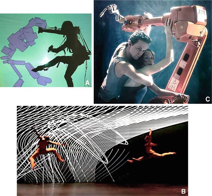
Chapter 4
So You Think You Can Dance? Rhythmic Flight
Performances with Quadrocopters

Angela P. Schoellig, Hallie Siegel, Federico Augugliaro and Raffaello D’Andrea

4.1 Rhythmic Flight with Quadrocopters

   Fly with the music. —Song title by DJ Grande

This chapter presents a set of algorithms that enable quadrotor vehicles (such as
the ones depicted in Fig. 4.1) to “fly with the music”; that is, to perform rhythmic
motions that are aligned with the beat of a given music piece.
   We design feasible periodic motion patterns based on a model of the quadrocopter,
which describes the dynamic capabilities of the vehicle. Control algorithms based on
the vehicle model stabilize the vehicle in the air and guide it along the desired flight
paths. However, without additional adaptation algorithms, the quadrocopter does not
follow the desired path with the required accuracy resulting in a motion that is not
in sync with the music. To perfect the vehicle’s flight performance, measurements
obtained from flight experiments are used to adapt the motion parameters sent to
the vehicle (‘commanded trajectory’ in Fig. 4.2). This adaptation can be done online
(during a flight performance) or offline (before a flight performance). The results are

This chapter summarizes results that have previously been published in [1–5]. Parts of those
papers are reproduced here for the sake of completeness..

A. P. Schoellig (B)
Institute for Aerospace Studies, University of Toronto, Toronto, Canada
e-mail: schoellig@utias.utoronto.ca
H. Siegel · F. Augugliaro · R. D’Andrea
Institute for Dynamic Systems and Control, ETH Zurich, Zurich, Switzerland
e-mail: siegelh@ethz.ch
F. Augugliaro
e-mail: faugugliaro@ethz.ch
R. D’Andrea
e-mail: rdandrea@ethz.ch

A. LaViers and M. Egerstedt (eds.), Controls and Art,                                          73
DOI: 10.1007/978-3-319-03904-6_4, © Springer International Publishing Switzerland 2014
74 A. P. Schoellig et al.
Fig. 4.1 A flight performance of multiple quadrocopters timed to music. (Photo Federico
Augugliaro)
Fig. 4.2 High-level control architecture used for implementing rhythmic flight performances. Key
components are the offline trajectory planning and online trajectory adaptation. (Position, velocity,
and acceleration refer to the translational coordinates and heading corresponds to the vehicle yaw)
flight maneuvers that closely follow the desired periodic motion pattern (‘desired
trajectory’ in Fig. 4.2) and align with the beat of the music.
This work can be viewed as a proof-of-concept result that shows the feasibility
of rhythmic flight and represents an important step toward our vision of creating
multivehicle aerial ‘dance’ performances.
4.1.1 Vision of a Quadrocopter Dance Performance
It takes an athlete to dance. But it takes an artist to be a dancer.
—Shanna LaFleur
Quadrocopters are exceptionally agile and “athletic” vehicles, but it takes more than
agility to create a musical flight performance that is both viable and convincing. We
envision a troupe of quadrocopters flying together across a big open stage—their
movement choreographed to the rhythm of the music, their performance coordinated
and skilled, and their choreography well-suited to their abilities and to the character
of the music. A quadrocopter “dance”.
A preliminary framework for designing and executing coordinated flight choreog-
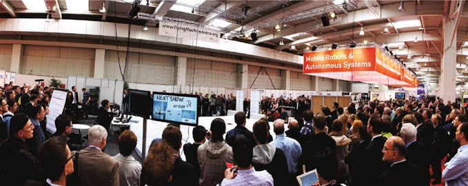
raphy to music has been implemented at the ETH Flying Machine Arena (Fig. 4.3).
4 So You Think You Can Dance?                                                                    75

Fig. 4.3 The ETH flying machine arena. Left Schematic drawing showing the motion capture
camera system that provides accurate measurements of the vehicle’s six degrees of freedom, position,
and attitude. Right Photo of the installation at ETH Zurich. (Photo Raymond Oung)

In this framework, the underlying vehicle control is done automatically, while the
high-level motion design is left to a human “choreographer”. This work-in-progress
currently enables the human operator to generate choreographies by assigning motion
elements to individual music segments that correspond to the music’s character. In
addition to the algorithms presented herein, support is provided by, for example,
a library of predefined, parameterized motion elements and a collision-free trajec-
tory generator, which can be used for smoothly connecting single motion elements.
Video sources of various quadrocopter flight performances are found at www.tiny.
cc/MusicInMotionSite.

4.1.2 Artistic Motivation

   As robots have grown more advanced, they have become our mirrors, as we watch the way
   they perform activities that we do as well. And as we watch, secrets are unlocked—secrets
   about how we, housed in our own biological frameworks, operate.
   —Rodney Brooks, roboticist and entrepreneur

The embodied mind thesis [6], which straddles such diverse fields as philosophy, psy-
chology, cognitive theory, neurobiology, robotics, and artificial intelligence argues
that all aspects of cognition are shaped by the experiences of the body; that how
we perceive the world around us (through our sensory system) and how we move
through and interact with this world (through our motor system) intrinsically deter-
mines the ways in which we think and experience. Proponents of “embodied AI”,
such as Rodney Brooks [7] and Rolf Pfeifer [8], argue that for machines to be truly
intelligent, they must have sensory and motor skills, and be connected to the world
through a body.
    It is interesting to consider the idea of “embodiment” also from the perspective
of professional dancers, choreographers, and athletes—people for whom the ability
to sense and move in the world forms a critical part of their work. In a paper entitled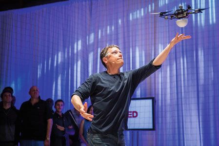
76                                                                    A. P. Schoellig et al.

“The Dance: Essence of Embodiment” [9] the philosopher/dancer duo Betty Block
and Judith Lee Kissell describe dance as an “embodied way of being-in the-world,”
and that “an analysis of dance is a profoundly enriching way to better understand
embodiment itself.” In other words, to dance is to be an expert in embodiment.
    It is no wonder, then, that robotics researchers have turned to dance as a means
of understanding gesture and movement. Examples are provided in the subsequent
Sect. 4.1.3.2. Note that many of these robotic/dance experiments involve humanoids
and/or robotic arms that mimic human limbs. Indeed, mimicry is a proven means
of generating understanding: much can be learned by reverse-engineering human
movements and gestures.
    But what happens when the “body” is not human? When the body is no longer
constrained by the limits of arms, legs, torso, and head? In this research project, where
quadrocopters learn and perform “dance”, mere mimicry of human movement is no
longer sufficient. A whole new meaning of “embodiment” begins to emerge.
    It is obvious that the quadrotor body is mechanically different from the human
body. It does not have arms, legs, or a head, but instead has rotating blades. Because
it flies, it occupies three-dimensional space in a way that we humans cannot. Its
movements are fundamentally different from ours: while we generate movement by
pushing off a hard surface (such as the ground), a quadrocopter creates movement
by “pushing” on air. These fundamental differences make it a challenge to design
motions for quadrocopters that can be recognized as dance by humans, and that can
been interpreted by human eyes as being “expressive”.
    Yet for all these differences, when it comes to dance performance, quadrocopters
and humans share much in common as well. First and foremost, “dance”—whether
performed by humans or by quadrocopters—is an exploration of three-dimensional
space that must respect the boundaries of both the performance space and the body
of the performer. Both humans and quadrocopters have limits to their abilities, and
not every sequence of movements is feasible. In human dance, during a ballet barre
exercise, for example, a Développé movement does not follow logically from a Plié
(see Chap. 9 ); for quadrocopters, subsequent movements require smooth transitions
without jumps in the vehicle position or attitude. Rhythmic ability is another feature
shared by both humans and quadrocopters: when music is present, human motion is
easily adapted to its meter, and with beat extraction software, this feat is accomplished
by quadrocopters, too. Another commonality is the ability to dance in groups: human
dance performances often feature troupes of dancers interacting with each other in
a shared space; advances in trajectory planning allow quadrocopters to also share
a space in a coordinated fashion without fear of collision. Humans also practice
to perfect their skills—something we can enable in quadrocopters as well using
parameter learning schemes [4]. And finally, humans teach and learn from each
other; while cooperative machine learning remains to be explored in-depth, current
research in this area is promising and suggests that shared learning could greatly
enhance the learning process.
    For robotics researchers, it is these commonalities that make an experiment
in quadrotor dance so interesting. If the mechanical differences between humans
and quadrocopters make it challenging for us to see them as “dance objects” or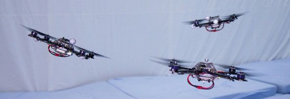
4 So You Think You Can Dance?                                                                 77

“dancers”, these differences are also what make quadrocopters capable of exploring
and experiencing three-dimensional space in a way that humans physically cannot.
For example, quadrocopters can engage with the three-dimensional space of the
stage, including its full height, and can leverage air to generate movement—feats
no human can do. In other words, what is challenging about quadrotor dance is also
potentially liberating: when humans interface with quadrocopters by composing and
executing quadrotor choreography, it opens up a new means of extending our own
bodies into new physical and technological worlds.
   Seen in this light, quadrocopters could become our dance partners, and the human–
machine interface could become the cybernetic means through which we extend
ourselves into new ranges of space and motion. This project is a first step toward that
vision.

4.1.3 The Interplay of Dance and Technology

   Dance and technology can shake hands but not at the expense of forgetting the essence of
   dance.
   —Tero Saarinen, dancer and choreographer

The interplay of dance and technology has long been a space for experimentation,
and a source for inspiration, innovation, and new developments. While technology
has provided new means for dance expression and challenged dancers to rethink their
art, dance has often challenged the state of the art of technology and motivated new
technological developments. An early example is the theatrical lighting pioneered
by the dancer Loie Fuller in the 1890s. Loie Fuller incorporated multicolored light
in her performances and established stage lighting as a new dimension for dance
expression. In addition, Fuller’s work pushed the boundaries of current technology
and resulted in several patents related to stage lighting technology.

4.1.3.1 Information Technology and Dance

In the past 50 years, computer and information technology have influenced and
transformed dance. The term “dance technology” has become a synonym for the
relationship between dance and information technology [10, 11]. Attracted by the
potential of this new field, dance performers, teachers, choreographers, and computer
scientists have explored the partnering of two disciplines that are, as stated in [10],
quite different: “Dance and technology make seemingly odd partners. Dance is the
most ethereal of art forms and computer technology perhaps the most concrete of
sciences. Whereas technologists deal with the logical, the scientifically verifiable,
dancers, as artists, deal with the illogical, i.e. inspiration and finding truth in that
which cannot be spoken.”
78                                                                          A. P. Schoellig et al.

Fig. 4.4 The interplay of dance and technology. a Performance 100d11A0N1C00E1 of Carol Cun-
ningham, April 2003: real-time animated projection of dancers’ movement onto three large screens
using motion capture (Photo David Umberger); b Performance Apparition of Klaus Obermaier and
Ars Electronica Futurelab (www.exile.at), Ars Electronica 2004: interaction of dance and multime-
dia with real-time visual content generation; c Performance Human interface of Thomas Freundlich,
May 2012: two dancers and two industrial robots perform together (Photo Johanna Tirronen)

   Work at the interface of information technology and dance has advanced both
disciplines by (i) integrating dance, emotions, and human character into computer
technology and animations, and (ii) establishing new analysis tools and means of
expression for dance performances.
   Work in (i) has focused on computer graphics applications and aimed to create
human-like virtual characters that are able to dance. Human motion capture data has
been used to understand, model, and imitate human dance behavior [12, 13].
   In (ii), information technology has led to new methods for expressing, creating,
assessing, and instructing dance (cf. [14, 15]). Results include interactive per-
formances of human dancers with computer-generated sound and images (e.g.,
computer-animated virtual dancers projected on a wall) [15–17], responsive
4 So You Think You Can Dance?                                                       79

environments where the dancer’s movement controls video, audio, and/or lightning
[18, 19], computer-assisted choreography design based on a language for human
movement representation and on virtual dance animation [11, 20], motion tracking
and capture to record or teach a piece [21], and multimedia in dance education [22,
23]. Figure 4.4, photos a and b show two different stage performances that explored
the technological possibilities for new forms of dance expression. Obermaier says
[24], “The goal was to create an interactive system that is much more than simply an
extension of the performer, but is a potential performing partner”. Carol Cunning-
ham summarizes her work as follows, “Motion capture is another tool for expression.
The image may be on screen and generated by technology, but it’s an extension of
the body”. Resembling human movement (Fig. 4.4a) and extending human motion
into new spaces (Fig. 4.4b) were goals of the dance and technology partnering with
the following outcome [18]: “The new convergences between dance and technology
reflect back on the nature of dance, its physical-sensory relationship to space and the
world, its immediate, phenomenological embodiedness, its lived experience in one
place”.

4.1.3.2 Robotics and Dance

As technology has advanced in the last 10 years and robots have become more
approachable, they have found their way into dance just as information technology
has done before. The physical embodiment of robots and their abilities to interact
provide a new means for dance expression as well as for studying human–robot
interaction and human dance.
   Research on robotics and dance has come a long way: from building robots that are
capable of executing human-like motions and enabling them to imitate human dance,
to enabling robot–human interactions in dance performances, adapting robot dance
to human preferences, and understanding human dance through robots. As dance has
previously been a human-centered discipline typically designed, performed, and eval-
uated by humans, research into “dancing robots” has primarily dealt with humanoid
robots and aimed for human-like behavior in robots. In this work, we consider a
new embodiment—a group of flying robots—but still face similar questions such
as: What is dance? What do humans recognize as dance? Which algorithms enable
dance-like behavior in robots?
   First approaches toward robotic dance of humanoid robots tried to imitate human
dance motion. In [10] basic dance motions for a robotic arm were designed using
choreographic elements from human dance such as shape, space, time, and force. For
humanoid robots, data from human demonstrations (obtained using a motion capture
system) was used to define basic robot dance motions, which—when concatenated—
create full robot choreographies [25–28]. A perfect example for human imitation is
a female android created by Japanese roboticists, which sings and dances along with
80                                                                  A. P. Schoellig et al.

a troupe of humans.1 The android’s motion was created by a professional choreog-
rapher using a tool proposed in [29].
    Recent work aims to understand the rules of human dance, which may ultimately
lead to a larger robot autonomy when executing dance. One approach is based on
the concept of human dance styles and detailed in the Chap. 9 of this book. Instead
of robots that follow preprogrammed motions, various styles of human movement
are defined, which in turn can be reproduced on a humanoid robot by generating
sequences of motions autonomously based on underlying rules. Other approaches
presented in this book try to understand human flocking in order to derive multiagent
behavior (see Chap. 2) and the human communication through movements (Chap. 3).
Other concepts that could explain what humans recognize as dance are skill-based
approaches [30] (defining fundamental joint relationships such as Opposite, Sym-
metry and Formation and learning likable sequences from human feedback), effects
related to motion synchrony and timed repertoire changes [31], and automatic motion
selection based on musical mood [32] or musical emotions [33, 34].
    Moreover, researchers currently investigate the interaction between humans and
their robotic counterparts, and potential adaptation schemes for robots. The adapta-
tion of a robot’s dance behavior to human preferences is described in [35]. In [36–39]
the rhythmic behavior of the robot adapts to the human based on appropriate esti-
mation techniques that predict the human motion. Stage performances focusing on
the human–robot interaction include Thomas Freundlich’s performance in Fig. 4.4c
and also the work in Chap. 9 of this book. Moreover, recently two artistic perfor-
mances have featured quadrocopters on stage with human actors/dancers [40, 41];
these focused on the interplay between humans and machines, and had skilled human
operators for controlling the quadrocopters.

4.1.3.3 Relationship to Our Work

The history of technology and dance provides a great context for our experiment,
where the performers of the dance are a swarm of quadrotor vehicles. Their flight
capabilities may offer—similarly to how humanoid robots have done before—new
means of dance expression, including motions in the full three-dimensional space.
New challenges result from the nonhuman-like body shape and motion character-
istics. While work on humanoid robots has largely imitated human dance behav-
ior, choreographies for quadrocopters must rethink the question, “What do humans
recognize as dance?,” and define quadrotor motions accordingly. Nevertheless, ideas
for human dance choreography (such as shape, space, time and force) and concepts
developed for humanoid robots may partially apply and/or may be a great source for
inspiration. Overall, by studying concepts and algorithms for creating “dance-like”
performances (including human–robot interaction, adaptation to the human behavior
or motion planning) not in the context of the human body may enable us to understand
more generally what makes robots move in a way that humans can relate to.

1   Video found at http://youtu.be/3JOzuTUCq6s.
4 So You Think You Can Dance? 81
4.1.3.4 A Final Note
Human dance has proven to be an inspiration for technology developments. Moreover,
technology has proven to extend the vocabulary of dance creation and performance
to an extent that we are often not aware of. An example of the tangible connec-
tion between robots and humans is a (human) dance style called “robot dance” that
became popular in the 1980s and that attempts to imitate a dancing robot. The style
is characterized by jerky mechanical movements. Inspiration inevitably goes both
ways: from human dance to technology and from technology to human dance. Just
as our project is a robotics research experiment, it is also an experiment in dance and
choreography.
4.1.4 First Steps Toward a Rhythmic Flight Performance
Art challenges technology, and technology inspires art.
—John Lasseter, chief creative officer at Pixar and Walt Disney Animation Studios
John Lasseter’s quote reflects the character of many past contributions at the interface
of dance and technology (cf. Sect. 4.1.3). It also provides the context for our work
toward a rhythmic flight performance of multiple quadrocopters. While the techno-
logical capabilities available today (such as small-sized off-the-shelf flying robots)
inspired us to think about “dancing quadrocopters” in the first place, implementing an
aerial choreography challenged the current knowledge in multivehicle autonomous
flight and led to novel research results, cf. [1–4, 42].
In this chapter, we focus on the research questions that are at the core of the pro-
posed project. We show how control theory can be used to approach these questions
analytically, and offer an intuitive explanation of our findings.
In particular, the topics investigated in this book chapter are:
1. Quadrocopter Dynamics: How do quadrocopters move? Which motions are pos-
sible with quadrocopters?
2. Motion Design: How to generate “dance-like” quadrocopter motions?
3. Motion Feasibility: Which motions are feasible given the actuator and sensor
constraints of the vehicle?
4. Quadrocopter Control: How do quadrocopters execute their movements?
5. Motion Synchronization: Can quadrocopters move in the rhythm of the music?
How well can they perform a rhythmic motion?
6. Rhythmic Performances: What has been accomplished to date?
The above questions are driven by the goal of creating a rhythmic flight perfor-
mance. The answers to these questions are obtained from control theoretic analysis
and design.
It is also interesting to make the connection to Chap. 5 here, where similar ques-
tions are considered for a different system, namely robotic marionettes, and tools82 A. P. Schoellig et al.
from controls are used to address the issue of feasibility, motion planning, and
timing. An opposite approach is taken in Chap. 7, where music is generated from
motion, where synchronization of motion and music plays an equally important role.
4.2 Quadrocopter Dynamics: How do Quadrocopters Move?
Dance is the language of movement. It is the realization of the body’s potential as an instru-
ment of expression.
—Victorian Board of Studies Dance study design, 1994
Human dance expression is fundamentally tied to the human body and its physical
capabilities. As an “instrument of expression”, the human body seems to enable an
endless range of different movements and different movement qualities. Just imagine
how many poses there are for a human (without even considering movement): we can
stand with two feet on the ground and various hand, arm, finger, and head positions,
and can make an almost infinite number of facial expressions. Moreover, skilled
dancers can stand still on just one leg... The number of degrees of freedom of a
human body (that is, the number of independent joints and possible directions of
rotation in those joints) is large but nevertheless motions are constrained by the
limits of arms, legs, torso, and head.
In comparison, for a quadrocopter (see Fig. 4.5) there is only one position that
allows it to stand still; namely, being horizontal in the air and producing an upward
force with its propellers that is equivalent to the gravitational force acting on the vehi-
cle. Moreover, a quadrocopter has only six degrees of freedom: three translational (its
three-dimensional position) and three rotational (its attitude), see Fig. 4.5b. However,
with only four independent motors (Fig. 4.5a), quadrocopters are underactuated; that
is, rotational and translational motion cannot be controlled independently but are cou-
pled [43]. More insight into the coupling will be provided below, where we derive
a model for the quadrocopter dynamics from first principles and also specify the
constraints of the vehicle. The dynamics model and constraints define the dynamic
capabilities of the vehicle in mathematical terms. We provide an interpretation of the
findings with respect to our goal of generating rhythmic flight performances.
4.2.1 Dynamics Model of the Quadrocopter
The quadrocopter is described by six degrees of freedom: the translational position
s = (x, y, andz) measured in the inertial coordinate system O and the rotational
position (also called ‘attitude’) represented by the rotation matrix R(t) from the
body frame V to the inertial frame O as shown in Fig. 4.5b.
The translational acceleration of the vehicle is dictated by the attitude of the
vehicle and the total thrust produced by the four propellers. The translational motion4 So You Think You Can Dance? 83
(a) (b)
Fig. 4.5 a Control inputs of the quadrocopter. b Quadrotor position and attitude. Schematic of
the quadrocopter with: (a) the control signals sent to the vehicle being the body rates p, q, and r
and the collective thrust c, and (b) the quadrotor position and attitude V defined with respect to
the inertial coordinate system O. These control signals are converted by an onboard controller into
motor forces Fi , i ∈ {1, 2, 3, 4}
of a quadrocopter in the inertial frame O is described by
⎡ ⎤ ⎡ ⎤ ⎡ ⎤
ẍ(t) 0 0 ẍ = c b x
⎣ ÿ(t)⎦ = R(t) ⎣ 0 ⎦ − ⎣0⎦ ⇔ ÿ = c b y , (4.1)
z̈(t) c(t) g z̈ = c b z − g
where g is the acceleration due to gravity and c(t) is the collective thrust; that is, the
sum of the rotor forces Fi normalized by the vehicle mass m,
4
c= 1
m i=1 Fi . (4.2)
The motor forces Fi , i ∈ {1, 2, 3, 4}, represent the inputs to the quadrocopter (see
Fig. 4.5). The values (b x , b y , b z ) correspond to the third column of the rotation
matrix, namely (R13 , R23 , R33 ), and represent the direction of the collective thrust
in the inertial frame O.
Each rotor produces not only a force Fi , i ∈ I = {1, 2, 3, 4}, in the positive Vz
direction, but also a reaction torque Mi perpendicular to the plane of rotation of the
blade, see Fig. 4.5a, where
Mi = k Fi , k = const, (4.3)
describes the relationship between the motor force Fi and the associated reaction
torque Mi . The parameter k is given by the motor characteristics, see [43] for details.
Rotors 1 and 3 rotate in the negative Vz direction, producing a moment that acts in the
positive Vz direction; while rotors 2 and 4 rotate in the opposite direction resulting in
reaction torques in the negative Vz direction. Given the inertia matrix I with respect to
the center of mass and the vehicle frame V, the rotational dynamics of the body-fixed
frame are given by84 A. P. Schoellig et al.
Table 4.1 Quadrocopter parameters
Definition Value
m Mass of vehicle 0.468 kg
L Vehicle arm length 0.17 m
Ix Inertia around vehicle V x-axis 0.0023 kg m2
Iy Inertia around vehicle V y-axis 0.0023 kg m2
Iz Inertia around vehicle Vz-axis 0.0046 kg m2
k Motor constant 0.016 m
Fmin Minimum rotor force 0.08 kg m/s2
Fmax Maximum rotor force 2.8 kg m/s2
⎡ ⎤
L(F2 − F4 )
I Ω̇ = ⎣ L(F3 − F1 ) ⎦ − Ω × I Ω, (4.4)
k(F1 − F2 + F3 − F4 )
where Ω = ( p, q, r ) represent the quadrocopter angular body velocities around
the body (Vx, V y, Vz) axes and L is the distance from each motor to the center of
the quadrocopter. The vehicle’s principal axes coincide with the vehicle frame axes
resulting in a diagonal inertia matrix with entries (I x , I y , Iz ), where I x = I y because
of symmetry.
The rotation matrix R evolves according to (cf. [44])
⎡ ⎤
0 −r (t) q(t)
Ṙ(t) = R(t) ⎣ r (t) 0 − p(t)⎦ , (4.5)
−q(t) p(t) 0
In our setup, an onboard controller closes the loop on the angular body velocities
Ω using onboard gyroscope measurements. As a result, the control signals sent to the
the quadrocopter are the collective thrust command cc and the commanded angular
body velocities Ωc = ( pc , qc , rc ), see Figs. 4.2 and 4.9. Based on the commanded
values (Ωc , cc ) and the gyroscope measurements, the onboard controller calculates
the required motor forces Fi , i ∈ I.
The specific vehicle parameters for the quadrocopters used in this work (see
Fig. 4.1) are given in Table 4.1.
4.2.2 Vehicle Constraints
The agility of the quadrocopter is constrained by the minimum and maximum force
of a single motor, Fmin ≤ Fi ≤ Fmax , i ∈ {1, 2, 3, 4}, with Fmin > 0, since the
motors cannot reverse their direction. The collective thrust is bounded by
cmin ≤ c ≤ cmax with cmin = 4 Fmin /m, cmax = 4 Fmax /m. (4.6)4 So You Think You Can Dance? 85
In addition, due to the motor dynamics the rate of change of the motor forces is
bounded in reality and the turn rates must be bounded because of the limited mea-
surement range of the gyroscopes used for onboard vehicle control. We neglect both
limitations in the following sections to simplify the presentation. The bounds of the
thrust rate Ḟi and the turn rates Ω are high (23.9 kg m/s3 and 25 rad/s, respectively)
and do not significantly affect the results in Sect. 4.4.
4.2.3 Implications for a Rhythmic Flight Performance
The above equations describe the motion capabilities of a quadrotor vehicle. From
(4.1) we see that the vehicle acceleration is always perpendicular to the plane of
the rotors; that is, for a motion in the x, y-direction the quadrocopter must tilt. The
translational and rotational degrees of freedom are, therefore, coupled and cannot
be specified independently. A rotation of the quadrocopter is achieved by sending
appropriate turn rates Ωc , see (4.5). The rotational dynamics around the Vx- and
V y-axes are symmetric, see (4.4), and fast due to the low rotational inertia terms
(Table 4.1).
One set of independent motion parameters for a quadrocopter is its three-
dimensional position over time and the evolution of the heading angle, cf. [43] and
Fig. 4.7. Compared to the human body, the “body’s potential” of a quadrocopter for
expressive movements is therefore limited to the position and heading in space over
time. Finding motion patterns that are convincingly expressive to the human eye is
not trivial and is discussed in Sect. 4.3.
4.3 Motion Design: What is a Dance Step for a Quadrocopter?
Dance is a poem of which each movement is a word —Mata Hari, dancer
As human dance choreography is typically described by sequences of basic move-
ments, we expect a flight performance of quadrocopters to be composed of basic
motion elements that—when combined into sequences—allow for a multifaceted,
meaningful quadrocopter choreography. As a first step, our goal is to develop basic,
rhythmic motion elements that can be executed by quadrocopters and timed to the
music beat. These basic rhythmic flight motions represent the “words” that may later
tell a “poem”.
Periodic motions are a natural human response to hearing a recurring music beat:
we often clap, sway, or tap our feet when we hear music. In our research, we want
the flying vehicle to mimic this behavior. Periodic motion elements thus represent
the basic building blocks of our choreography. As highlighted above, the degrees of
freedom of a quadrocopter motion are restricted to the three-dimensional position
and its heading. We therefore develop motion elements that show a periodicity in the86 A. P. Schoellig et al.
Fig. 4.6 A periodic side-to-side motion with the music beats occurring at the outermost points of
the movement
vehicle position and use the vehicle’s agility to achieve temporal variety. Below we
present a parameterized motion description that enables motion variations that are
indispensable when aiming for an expressive choreography.
4.3.1 Music Analysis
The more you understand the music, the easier you can dance.
—Orlando Gutinez
Fundamental to our goal of creating rhythmic flight movements is a tight connection
of motion and music. We therefore analyze the music first and then assign appropriate
motions to the vehicle. The goal of the music analysis is to extract music features and
their respective time signatures. The result is a vocabulary that describes the song’s
temporal development. We use this time information to assign suitable quadrocopter
motions to different sections of the song.
In order to achieve rhythmic behavior, we are particularly interested in the music
beat, which represents the basic rhythmic unit of a song and plays a prominent role
in the motion design. Currently we use the BeatRoot software tool [45] to extract
beat times from a song. We store music beats and their respective start times in a text
file. This information is then used to create matching flight trajectories; for example,
movements that reflect the music tempo.
A simple example that highlights the key idea is shown in Fig. 4.6: the quadro-
copter performs a planar side-to-side motion where, at beat times, the vehicle reaches
the outermost points of the motion, either on the left or right.
4.3.2 Periodic Motions
When you dance, your purpose is not to get to a certain place on the floor. It’s to enjoy each
step along the way. —Wayne Dyer. author
We specify basic, rhythmic motion elements as the evolution of the quadrocopter’s
translational position in three dimensions sd (t) = (xd (t), yd (t), z d (t)) and its head-
ing ψd (t) over time. We introduce parameterized motion primitives
sd ( p, t), ψd ( p, t), (4.7)4 So You Think You Can Dance? 87
which depend on aset of adjustable motion parameters p and are defined over a finite
time interval t ∈ t0 , t f ⊂ R, t f < ∞. Parameterized motion primitives allow
for variety and expressiveness in the choreography design. Consider a horizontal
circle, for example, where the radius, speed of rotation, and center point can be
adapted depending on the use case. Note that the vehicle heading ψd can be designed
independently of the position and is not explicitly considered in the following.
Our objective is to offer a similar range of motions as is used in human dance
composition. In this context, we ask: Which choices does a professional dance chore-
ographer have when creating a performance? How can we provide the tools and
degrees of freedom necessary for implementing an expressive performance on the
quadrocopter?
Four fundamental choreographic elements—time, space, energy, and structure—
are commonly used by professional dancers, choreographers, and dance teachers to
build choreography with interest, dynamics, and estethic appeal, cf. [46, 47]. These
parameters provide a framework for meaningful quadrocopter choreography, and are
described as follows:
Space Space refers to the area the dancer is performing in. It also relates to how
the dancer moves through the area, as characterized by the direction and path of
a movement, as well as its size, level, and shape.
Time Time encompasses rhythm, tempo, duration, and phrasing of movements.
Using time in different combinations can create intricate visual effects. Ideas
such as quick-quick, slow, or stop movements are examples.
Energy Energy relates to the quality of movement. This concept is recognizable
when comparing ballet and tap dance. Some types of choreography are soft and
smooth, while others are sharp and energetic.
Structure Structure represents the organization of movement sequences into larger
concepts: the combination and variation of movements using recurring elements,
contrast, and repetition. Movements can even follow a specific story line to convey
certain information through a dance.
Examples illustrating the four elements of dance are found in [46, 47].
One way of introducing parameterized, rhythmic motion primitives that capture
a wide range of different movements is as a Fourier series [48],
N
sd (t) = a0 + ak cos (k ωd t) + bk sin (k ωd t) , (4.8)
k=1
where ωd = 2π/T represents the fundamental frequency corresponding to a music
beat of frequency 1/T , where beats are T seconds apart. Additional design para-
meters are the constant vectors a0 , ak , bk ∈ R3 , k ∈ K = {1, 2, . . . , N } , and
N ≥ 1; that is, p = {ωd , N , a0 , ak , bk | k ∈ K}. The parameters characterize the
desired translational position sd (t) of the quadrocopter and allow us to express the
key choreographic elements:88 A. P. Schoellig et al.
Fig. 4.7 An example of a periodic motion primitive studied in this chapter
Space The parameters a0 and ak , bk , k ∈ K define the amplitudes of the periodic
motion and, thus, the spacial dimension of the movement. These vectors also
specify the direction of the motion and the overall three-dimensional shape of the
curve.
Time The underlying rhythm is given by the frequency ωd . When the choreography
is set to music, the frequency ωd is related to the music’s tempo. Different tempos
can be combined when choosing N > 1. The overall duration of the motion can
be adjusted via t f .
Energy The higher the value of N , the more energetic and sharp are the possible
motions, cf. [48].
Structure The motion primitives described in (4.8) can be combined into sequences,
which can in turn be combined to create an overall choreographic performance.
Endless permutations are possible, much the way individual words can be com-
bined into a variety of sophisticated stories, or a series of gestures can be combined
to reveal a performer’s mood or emotion to an audience.
In short, the general motion description (4.8) reflects the fundamental choreo-
graphic elements and allows for a multidimensional choreography. Out of the vari-
ety of motions captured by (4.8), Fig. 4.7 illustrates the one with N = 3, T = 10,
a0 = (0, 0, 3), a1 = (0, 0, 1), a2 = (1, 0, 0), and b3 = (0, 1, 0), and a3 , b1 , b2 being
zero. A Matlab file for generating arbitrary motion primitives of the proposed type
is available online at www.idsc.ethz.ch/Downloads/QuadDance.
In order to make (4.7) and (4.8) a useful tool for choreographers, we need to
specify which motion primitives can be realized on the vehicle. The dynamics and
physical limits of the quadrocopter define the feasible sets of parameters p. This is
done in the next section.4 So You Think You Can Dance? 89
4.4 Motion Feasibility: What are the Physical Limits of a
Quadrocopter?
The dancer is restricted by self-limits, the limits of being in this body with these abilities and
not others.
—Sondra Horton Fraleigh in “Dance and the Lived Body: A Descriptive Aesthetics” [49]
Though dancers and athletes are trained to push the physical limits of their bodies
to extremes, they nonetheless remain constrained by the rules of physics. Quadro-
copters, too, are limited by their body’s dynamics (Sect. 4.2). For example, our
quadrocopters cannot keep a constant height when flying sideways with angles larger
than 66◦ (cf. Fig. 4.6). To create a “choreography” for quadrocopters, we must be
aware of and account for these physical limitations.
Below we describe a method for checking the feasibility of quadrocopter motions.
The approach, meant as a validation tool for preprogrammed quadrocopter perfor-
mances, is based on the first principles models in Sect. 4.2 and ensures that a desired
trajectory respects both vehicle dynamics and motor thrust limits. The goal is to deter-
mine sets of motion parameters p, cf. (4.7), (4.8), that represent rhythmic motions
that can be realized with a quadrocopter. The result of this analysis is a library of
feasible motion primitives that can be used to create multifaceted performances.
4.4.1 Motor Thrust Limits
For the subsequent feasibility analysis, we assume that motion primitives, cf. (4.7),
are twice-differentiable in time. This assumption is satisfied for the periodic motions
primitives (4.8) introduced in the previous section. Feasibility is formulated in terms
of the collective thrust limits (cmin , cmax ) and the motion parameters p. The objective
is to derive a set of inequalities that specify feasible parameter sets p given the limits
(cmin , cmax ).
For a desired motion primitive sd , we rewrite (4.1),
R n cd = s̈d + n g, (4.9)
where n = (0, 0, 1) and cd is the nominal thrust input required to achieve sd . Taking
the 2-norm, we can solve for cd , cd ≥ 0,
R n cd = s̈d + n g ⇔ cd = s̈d + n g . (4.10)
Recalling that sd = sd ( p, t) and (4.6), the inequalities guaranteeing the maximum
and minimum bounds of the collective thrust are
cmin ≤ s̈d ( p, t) + n g ≤ cmax , t ∈ t0 , t f . (4.11)90 A. P. Schoellig et al.
This feasibility requirement can be checked for any given desired motion
primitive sd ( p, t) by calculating its second time derivative. No further calculations
are necessary. In particular, the nominal quadrocopter inputs associated with sd ( p, t)
need not be determined in advance. The inequalities (4.11) exclude the majority of
infeasible parameters p and help to build an intuition as to what is feasible for a
quadrotor vehicle.
In order to be more precise, single motor constraints and turn rate constraints must
be considered, cf. Sect. 4.2.2. For those constraints explicit parameter-dependent
inequalities are generally difficult to derive (see [3] for details). Instead, in our cur-
rent software framework, we numerically assess the feasibility of a created motion
sequence before actual flight, see [50].
4.4.2 Example: Side-to-Side Motion
To demonstrate the above feasibility test, we consider a simple periodic motion that
falls into the framework introduced in (4.8): a horizontal side-to-side motion as
illustrated in Fig. 4.6. In fact, the side-to-side motion was the first rhythmic motion
that we implemented on a quadrocopter and executed to music [1].
The planar side-to-side movement is given by
xd (t) = A cos(ωd t), yd (t) = z d (t) = ψd = 0. (4.12)
The side-to-side motion is a special case of the general motion primitive description
(4.8), where N = 1 , a1 = (A, 0, 0) and a0 , b1 = (0, 0, 0).
To determine feasible combinations of amplitudes A and frequencies ωd , we
calculate the second derivative of (4.12) and insert it into (4.11):
cmin ≤ A2 ωd4 cos2 ωd t + g 2 ≤ cmax . (4.13)
For a given pair (A, ωd ), these inequalities must be satisfied for all t ∈ [0, T ].
Therefore, it is enough to consider the maximum and minimum values over T . We
obtain
Aωd2 ≤ cmax2 − g 2 and cmin ≤ g. (4.14)
The second inequality must be satisfied in order for a quadrocopter to be able to
land. In brief, all parameter pairs (A, ωd ) satisfying the inequality (4.14) represent
side-to-side motions that stay within the collective thrust limits (4.6).
For the vehicle parameters in Table 4.1, Fig. 4.8 illustrates the feasible set of side-
to-side trajectories (A, ωd ). The dark gray region contains parameter sets that are
infeasible due to the collective thrust limit, cf. (4.14). We also depict (light gray area)
the parameter sets that become infeasible when taking into account the minimum
and maximum force limits of each single motor (see Sect. 4.2.2); the corresponding4 So You Think You Can Dance? 91
1.5
Amplitude (m)
1 INFEASIBLE
0.5
FEASIBLE
0
0 5 10 15
Frequency (rad/s)
Fig. 4.8 Feasible parameter sets for the side-to-side motion primitive. The dark gray region denotes
parameter sets that are infeasible due to collective thrust limits; light gray denotes additional para-
meter sets that are infeasible due to the minimum and maximum force limits of each single motor
derivations are presented in [3]. From Fig. 4.8 we see that if we want to perform two
side-to-side motions per second (ωd ≈ 12.6 rad/s), a motion amplitude of 0.5 m is
clearly infeasible. We also see that for the side-to-side motion the single motor force
limits exclude only a small additional number of parameter sets. The inequalities
(4.11) represent a simple means to understand which motions are feasible.
4.5 Quadrocopter Control: How do Quadrocopters Execute
Their Movements?
Technique—bodily control—must be mastered only because the body must not stand in the
way of the soul’s expression.
—La Meri, dancer and choreographer
In Sect. 4.3 we introduced rhythmic motion elements with the goal of enabling expres-
sive choreography, where the movements were defined by the desired evolution of
the quadrocopter position over time. However, similarly to human dancers who con-
stantly work on perfecting their body control, quadrocopters require sophisticated
control algorithms to guide their “bodies” along the desired trajectories. Just recall
that the smallest mistake may lead to the vehicle falling out of the sky. In this section,
we derive a motion controller that maintains the quadrocopter on the specified tra-
jectory during actual flight.
4.5.1 Trajectory-Following Controller
The trajectory-following controller (TFC) accepts as input commanded positions,
velocities, and accelerations, as well as, a yaw angle trajectory (cf. Fig. 4.2):
(sc (t), ṡc (t), s̈c (t), ψc (t)) . (4.15)92 A. P. Schoellig et al.
Fig. 4.9 Cascaded control loops of the trajectory-following controller (TFC)
We usually obtain appropriate input commands directly from the desired sequence
of motion primitives (see Sects. 4.3 and (4.7)) by setting: sc (t) := sd (t) and ψc (t) :=
ψd (t). The respective time derivatives ṡc (t), s̈c (t) are also computed from the desired
trajectory sd (t), which is preplanned and known in its full length prior to flight.
The TFC is a standard component of our experimental testbed. Control is based on
precise measurements of the vehicle position and attitude (in our case, provided by a
motion capture system). The TFC receives the quadrocopter’s position s = (x, y, z),
velocity ṡ and attitude R from an estimator and, in turn outputs the body rate and
collective thrust commands (Ωc , cc ) to the vehicle, see Fig. 4.9. The TFC consists
of three separate loops for altitude, horizontal position, and attitude. While the TFC
operates in discrete time, the controller design is based on the continuous-time system
dynamics representation.
The altitude control is designed such that it responds to altitude errors (z − z c )
like a second-order system with time constant τz and damping ratio ζz ,
2ζz 1
z̈ = − (ż − ż c ) − 2 (z − z c ) + z̈ c . (4.16)
τz τz
It uses the collective thrust to achieve this. With (4.1) and (4.16), we obtain
cc = (z̈ + g)/b z . (4.17)
Similarly, the two horizontal position control loops are shaped based on (4.1) with cc
y
from (4.17). Commanded rotation matrix entries bcx , bc result. The attitude control
is shaped such that the two rotation matrix entries b , b y react in the manner of a
x
first-order system; that is, for x: ḃcx = (b x − bcx )/τ R P . This is directly mapped to the
commanded angular body velocities ( pc , qc ) using (4.5) and the estimated attitude R,
pc 1 R21 −R11 ḃcx
= y . (4.18)
qc R33 R22 −R12 ḃc
Vehicle yaw control can be considered separately, since rotations around the body Vz-
axis do not affect the above dynamics. The yaw controller is a proportional controller
and the resulting yaw angle rate is mapped to rc using the kinematic relations of4 So You Think You Can Dance? 93 Fig. 4.10 Side-to-side motion, no motion parameter adaptation. Top quadrocopter response (solid) for a desired oscillation in the x-direction (dashed). Bottom corresponding peak velocities, i.e., absolute value of vehicle velocity at the peaks of the desired trajectory. High peak velocities imply a large phase error Euler angles. The innermost loop, on board the quadrocopter, controls the angle rates ( p, q, r ) to the calculated set points ( pc , qc , rc ). In the ideal case, where the quadrocopter dynamics correspond to the model (4.1) and some other mild assumptions are made (see [4] for details), the derived controller yields perfect trajectory tracking. In summary, we have presented a control framework that enables an autonomous quadrocopter flight along a desired trajectory defining the vehicle position and the heading of the vehicle over time. 4.5.2 Tracking Performance of Periodic Motions When using the derived TFC to track the side-to-side motion (4.12), we considered before with sc (t) := sd (t) and ψc (t) := ψd (t) (that is, the desired periodic trajectory is directly sent to the vehicle controller), we observe, at steady state, a sinusoidal motion of the same frequency with a constant error in amplitude and phase, result- ing in asynchrony and spatial inaccuracies, as shown in Fig. 4.10 (top figure). The amplitude error of the quadrocopter response (black solid line) is obvious; the phase error between the reference trajectory and the actual quadrocopter response is hardly noticeable. However, small phase errors are very visible and audible in actual exper- iments as humans are especially sensitive to nonzero vehicle velocity at beat times (see [5] for more details). Correspondingly, the bottom plot of Fig. 4.10 illustrates the velocity of the quadrocopter at beat times; that is, when the reference trajectory reaches its maximum or minimum value. For periodic motions in three dimensions, a similar behavior is observed: phase shift and amplitude error are observed in each translational direction and are not necessarily equal in size. In this case, the shape of the resulting motion can change.
94                                                                             A. P. Schoellig et al.

Fig. 4.11 Vertical bounce motion, no motion parameter adaptation. The vehicle’s response (solid)
can differ in shape from the desired trajectory (dashed)

For example, a desired bounce motion (Fig. 4.11) results in a bent eight-shaped
vehicle motion.
   In order to achieve precise temporal and spatial tracking, we adapt the parameters
of the commanded trajectory (4.15) sent to the TFC in the next section. Later we
see that these parameters can be identified/learned prior to the flight performance in
order to effectively reduce initial transients.

4.6 Motion Synchronization: Can a Quadrocopter Move
    in the Rhythm of the Music?

     I like to see you move with the rhythm; I like to see when you’re dancing from within.
     —Bob Marley, singer and composer

“Moving with the rhythm” is the ultimate goal of this work, where we aim to control
the motion of quadrocopters to an external music signal. As highlighted in the pre-
vious section, pure feedback controlled to insufficient quadrocopter tracking with a
noticeable phase and amplitude error.
    The goal of this section is to prove the feasibility of a precise synchronization
between quadrocopter motion and music, where we use the term “synchronization”
loosely, inasmuch as it encompasses both spatial and temporal tracking accuracy. Our
strategy for coping with the aforementioned constant phase shift and amplitude error
is to adjust the motion parameters of the trajectory commanded to the underlying
trajectory-following controller (see Fig. 4.2). This means, for example, that if the
amplitude of the quadrocopter motion is larger than the desired one, we reduce
the commanded amplitude. Similarly, if the vehicle motion is lagging, we shift the
commanded trajectory by increasing the phase.
4 So You Think You Can Dance? 95
4.6.1 Synchronization: The Basic Idea
To illustrate the basic idea of the “feed-forward” strategy, we consider the side-to-
side motion in (4.12) and Fig. 4.6, where we adapt the commanded amplitude Ac
and phase θc of the commanded trajectory sc (t) (Fig. 4.2),
xc (t) = Ac cos(ωd t + θc ), yc (t) = z c (t) = ψc = 0. (4.19)
to achieve synchronization. Our original results on this topic were presented in [1].
4.6.1.1 Online Correction
The motion parameters of the commanded trajectory are set to
θc (t) = θon (t), Ac (t) = Ad + Aon (t), (4.20)
where the subscript “on” indicates the online correction terms. They are updated in
real time, during the flight.
As illustrated in Sect. 4.5.2, the response of the controlled quadrocopter system
to a side-to-side reference signal (4.12) when choosing sc (t) := sd (t) and ψc (t) :=
ψd (t) is a sinusoidal signal with the same frequency but shifted phase and different
amplitude,
x(t) = (A(t) + Ad ) cos (ωd t + θ(t)) . (4.21)
To determine the additive errors in amplitude A(t) and phase θ(t), the two refer-
ence signals, rcos (t) = cos ωd t and rsin (t) = sin ωd t, are multiplied by the position
estimate x(t) and integrated over N periods, that is T = (2π N )/ωd . Assuming a
constant phase shift and an amplitude error during that time interval
θ(v) = θt = constant, A(v) = At = constant, t − T ≤ v ≤ t, (4.22)
we obtain
1 t At + Ad
η1 (t) = x(t)rcos (t)dt = cos(θt ),
T t−T 2
(4.23)
1 t At + Ad
η2 (t) = x(t)rsin (t)dt = − sin(θt ),
T t−T 2
and
At = 2 η1 (t)2 + η2 (t)2 − Ad ,
(4.24)
θt = − arctan (η2 (t)/η1 (t)) .
The values θt , At can be interpreted as the mean value of the phase and ampli-
tude errors during the last period, and when considering Fig. 4.10, the phase and96 A. P. Schoellig et al.
Fig. 4.12 Side-to-side motion. Top online motion parameter adaptation only. Quadrocopter
response (solid) for a desired oscillation in the x direction (dashed) Bottom offline motion parameter
adaptation, with online motion parameter adaptation turned on after two periods
amplitude errors are in fact constant (after a transient phase). Therefore, (4.22) is a
valid assumption in steady state.
The online correction terms are calculated by integrating the errors according to
t t
Aon (t) = k A Aτ dτ , θon (t) = kθ θτ dτ , (4.25)
0 0
where the gains kθ , k A are chosen to ensure convergence of the online correction
terms to the steady-state values θon,∞ and Aon,∞ , respectively.
Using the proposed online parameter adaptation strategy (4.20), (4.25), the errors
in amplitude and phase are effectively regulated to zero, see Fig. 4.12 (top figure)
and compare to Fig. 4.10. We observe a substantial transient phase before the online
correction terms attain steady state, see Fig. 4.13. This is mainly due to the fact
that the error identification scheme (4.23), (4.24) only provides reliable values after
several periods.
4.6.1.2 Offline Identification
The steady-state values θon,∞ , Aon,∞ obtained from the online correction are repeat-
able (that is, different runs of the same experiment produce the same result). Con-
sequently, the correction values can be extracted once, and later applied to improve
the transient performance; that is, the tracking during the initial period of a motion.
For the phase, we use
θc (t) = θoff + θon (t) with θoff = θon,∞ . (4.26)4 So You Think You Can Dance? 97
Fig. 4.13 Side-to-side motion, convergence of online correction terms
The equation for the amplitude is similar. The subscript ‘off’ indicates the offline
motion parameters identified prior to the experiment. Figure 4.12 (bottom figure)
shows the corresponding result for the side-to-side motion. The transient time is
substantially decreased.
4.6.1.3 Reduced Offline Identification
Thus far, offline parameters must be identified for each side-to-side motion (Ad , ωd )
individually. To draw further conclusions, we consider the steady-state values in the
following form: the amplitude-normalized amplification factor,
αon,∞ = (Ad + Aon,∞ )/Ad , (4.27)
and the steady-state phase θon,∞ as before. Experiments in [1] have shown that the
steady-state values (αon,∞ , θon,∞ ) depend only on the motion’s frequency ωd . That
is, a single identification run must be completed for each frequency, the vehicle should
perform at and the resulting parameters can be used for any side-to-side motion at
this frequency with varying amplitudes.
4.6.2 Synchronization in Three Dimensions
We extend the previous results into three-dimensional (3-D) motion, which is com-
posed of sinusoidal side-to-side motions in each translational direction:
⎡ ⎤ ⎡ x ⎤
xd (t) Ad cos(ωdx t + θdx )
⎣ yd (t)⎦ = ⎣ A cos(ω t + θ )⎦ , ψd (t) = 0,
y y y
(4.28)
d d d
z d (t) Adz cos(ωdz t + θdz )
(x,y,z)
where θd represents a potential phase shift between the sinusoidal motions in
each direction. Bounces, ellipses, eights, and spirals can be obtained by appropriate
parameter choices.98 A. P. Schoellig et al.
Fig. 4.14 Sequence of motions with (dashed) and without (solid) feed-forward corrections. Offline
correction terms were obtained from a reduced identification. The errors of the desired trajectory
to the response of the vehicle (sd (t) − s(t)) are plotted. The motion sequence comprises: a circular
motion in 3-D, a swing motion in 3-D, and a horizontal circle
As shown in [4], a key assumption can be made for the given 3-D motion: each
translational direction can be treated separately. To this end, the motion parameters
in the commanded trajectory sc (t) are adjusted independently for each direction
according to the online strategy presented above. In addition, the offline identification
benefits from the directional decoupling and the quadrocopter symmetry in that the
x- and y- directions exhibit the same behavior and identification in one of the two
directions is sufficient.
Consequently, it is possible to develop an identification scheme that efficiently
identifies the offline correction terms for all periodic motions that can be expressed
in our framework (4.28): a single identification run over the relevant frequency range
with a 2-D motion primitive in x or y, and z is sufficient to completely identify all
necessary feed-forward parameters. The offline values are stored in a look-up table
ready to be used when performing new motions of (4.28).
In order to show the effectiveness of the reduced identification scheme, we per-
form a sequence of periodic 3-D motions with offline parameters obtained from an
oscillatory motion in 2-D (Adx = Adz = 0.4 m, ωdx = ωdz = ω and all other para-
meters zero). Figure 4.14 shows that the quadrocopter’s deviation from the desired
trajectory is clearly reduced when using the offline parameter adaptation strategy.
Note that the performance can be further improved by designing smooth transitions
between the motion of the sequence.
To conclude, we studied a feed-forward parameter tuning strategy that improves
the tracking performance of periodic motion primitives especially during transients
using preidentified correction terms and online parameter adaptation. The transla-
tional directions are independent, allowing for the efficient identification of a table
stored offline. In brief, we enable quadrocopters to fly to the rhythm of the music
with correctly scaled motions. This fulfills the requirements for a rhythmic motion.
4.7 Rhythmic Performances
People in the audience, when they’ve watched the dance, should feel like they’ve accom-
plished something, that they’ve gone on a journey.
—Paul Mercurio, actor and dancerYou can also read