SONICWALL GLOBAL MANAGEMENT SYSTEM SWITCHING - ADMINISTRATION GUIDE
←
→
Page content transcription
If your browser does not render page correctly, please read the page content below
SonicWall™ Global
Management System
Switching
Administration Guide
Contents                                                                                                                                                      1
  Configuring VLAN Trunking . . . . . . . . . . . . . . . . . . . . . . . . . . . . . . . . . . . . . . . . . . . . . . . . . . . . . . . . . . . . 3
  What is Switching? . . . . . . . . . . . . . . . . . . . . . . . . . . . . . . . . . . . . . . . . . . . . . . . . . . . . . . . . . . . . . . . . . . . . 3
  Benefits of Switching . . . . . . . . . . . . . . . . . . . . . . . . . . . . . . . . . . . . . . . . . . . . . . . . . . . . . . . . . . . . . . . . . . . 3
  Switching > VLAN Trunking . . . . . . . . . . . . . . . . . . . . . . . . . . . . . . . . . . . . . . . . . . . . . . . . . . . . . . . . . . . . . . 5
      About Trunking . . . . . . . . . . . . . . . . . . . . . . . . . . . . . . . . . . . . . . . . . . . . . . . . . . . . . . . . . . . . . . . . . . . . 5
  Viewing Reserved VLAN IDs . . . . . . . . . . . . . . . . . . . . . . . . . . . . . . . . . . . . . . . . . . . . . . . . . . . . . . . . . . . . . 8
  Editing VLANs . . . . . . . . . . . . . . . . . . . . . . . . . . . . . . . . . . . . . . . . . . . . . . . . . . . . . . . . . . . . . . . . . . . . . . . . . 9
  Adding VLAN Trunk Ports . . . . . . . . . . . . . . . . . . . . . . . . . . . . . . . . . . . . . . . . . . . . . . . . . . . . . . . . . . . . . . . 9
  Deleting VLAN Trunk Ports . . . . . . . . . . . . . . . . . . . . . . . . . . . . . . . . . . . . . . . . . . . . . . . . . . . . . . . . . . . . . 10
      Deleting a VLAN Trunk Port . . . . . . . . . . . . . . . . . . . . . . . . . . . . . . . . . . . . . . . . . . . . . . . . . . . . . . . . . 10
      Deleting Multiple VLAN Trunk Ports . . . . . . . . . . . . . . . . . . . . . . . . . . . . . . . . . . . . . . . . . . . . . . . . . . 10
  Enabling VLANs on a Trunk Port . . . . . . . . . . . . . . . . . . . . . . . . . . . . . . . . . . . . . . . . . . . . . . . . . . . . . . . . . 10
  Viewing Enabled VLANs . . . . . . . . . . . . . . . . . . . . . . . . . . . . . . . . . . . . . . . . . . . . . . . . . . . . . . . . . . . . . . . 11
  Deleting Enabled VLANs . . . . . . . . . . . . . . . . . . . . . . . . . . . . . . . . . . . . . . . . . . . . . . . . . . . . . . . . . . . . . . . 11

  Configuring Link Aggregation . . . . . . . . . . . . . . . . . . . . . . . . . . . . . . . . . . . . . . . . . . . . . . . . . . . . . . . . . 12
  Creating a Logical Link (LAG) . . . . . . . . . . . . . . . . . . . . . . . . . . . . . . . . . . . . . . . . . . . . . . . . . . . . . . . . . . . . 14
  Editing LAG Ports . . . . . . . . . . . . . . . . . . . . . . . . . . . . . . . . . . . . . . . . . . . . . . . . . . . . . . . . . . . . . . . . . . . . . 15
  Deleting LAG Ports . . . . . . . . . . . . . . . . . . . . . . . . . . . . . . . . . . . . . . . . . . . . . . . . . . . . . . . . . . . . . . . . . . . . 15
  Searching the Link Aggregation Table . . . . . . . . . . . . . . . . . . . . . . . . . . . . . . . . . . . . . . . . . . . . . . . . . . . . 16

  Configuring Port Mirroring . . . . . . . . . . . . . . . . . . . . . . . . . . . . . . . . . . . . . . . . . . . . . . . . . . . . . . . . . . . 17
  Configuring a Port Mirroring Group . . . . . . . . . . . . . . . . . . . . . . . . . . . . . . . . . . . . . . . . . . . . . . . . . . . . . . 17
  Enabling the Mirror Group . . . . . . . . . . . . . . . . . . . . . . . . . . . . . . . . . . . . . . . . . . . . . . . . . . . . . . . . . . . . . 19
  Searching the Port Mirroring Table . . . . . . . . . . . . . . . . . . . . . . . . . . . . . . . . . . . . . . . . . . . . . . . . . . . . . . 19
  Deleting a Port Mirroring Group . . . . . . . . . . . . . . . . . . . . . . . . . . . . . . . . . . . . . . . . . . . . . . . . . . . . . . . . 20

  Configuring Layer 2 QoS . . . . . . . . . . . . . . . . . . . . . . . . . . . . . . . . . . . . . . . . . . . . . . . . . . . . . . . . . . . . . 21
  Configuring the Scheduling Mechanism . . . . . . . . . . . . . . . . . . . . . . . . . . . . . . . . . . . . . . . . . . . . . . . . . . 22
  Configuring DSCP Mapping . . . . . . . . . . . . . . . . . . . . . . . . . . . . . . . . . . . . . . . . . . . . . . . . . . . . . . . . . . . . . 23
  Resetting to Default Values . . . . . . . . . . . . . . . . . . . . . . . . . . . . . . . . . . . . . . . . . . . . . . . . . . . . . . . . . . . . . 25

  Managing Layer 2 Discovery and LLDP/LLTD . . . . . . . . . . . . . . . . . . . . . . . . . . . . . . . . . . . . . . . . . . . . . 26
  About L2 Discovery and LLDP . . . . . . . . . . . . . . . . . . . . . . . . . . . . . . . . . . . . . . . . . . . . . . . . . . . . . . . . . . . 26
     Supported LLDP Modes . . . . . . . . . . . . . . . . . . . . . . . . . . . . . . . . . . . . . . . . . . . . . . . . . . . . . . . . . . . . 26
     Viewing L2 Discovery and LLDP/LLTD Interfaces . . . . . . . . . . . . . . . . . . . . . . . . . . . . . . . . . . . . . . . . 30
     Adding an LLDP Custom Profile . . . . . . . . . . . . . . . . . . . . . . . . . . . . . . . . . . . . . . . . . . . . . . . . . . . . . . 32
     Editing a Custom LLDP Profile . . . . . . . . . . . . . . . . . . . . . . . . . . . . . . . . . . . . . . . . . . . . . . . . . . . . . . . 34
     Deleting Custom Profiles . . . . . . . . . . . . . . . . . . . . . . . . . . . . . . . . . . . . . . . . . . . . . . . . . . . . . . . . . . . 35

  Configuring Switch Shield . . . . . . . . . . . . . . . . . . . . . . . . . . . . . . . . . . . . . . . . . . . . . . . . . . . . . . . . . . . . 37

  SonicWall Support . . . . . . . . . . . . . . . . . . . . . . . . . . . . . . . . . . . . . . . . . . . . . . . . . . . . . . . . . . . . . . . . . . 38
  About This Document . . . . . . . . . . . . . . . . . . . . . . . . . . . . . . . . . . . . . . . . . . . . . . . . . . . . . . . . . . . . . . . . . 39

                                                                                                      GMS Switching Administration Guide
                                                                                                                                                             2
                                                                                                                                Contents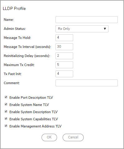
1
                          Configuring VLAN Trunking
      NOTE: This section describes advanced switching in GMS, which is different from managing a Dell X-Series
      switch or N-Series switch from a SonicWall Security Appliance.

      NOTE: Switching is available on all NSA 2650 and above and SuperMassive appliances.

What is Switching?
GMS provides Layer 2 (data link layer) switching functionality that supports these switching features:
   • VLAN Trunking – Provides the ability to trunk different VLANs between multiple switches.
   • Layer 2 Network Discovery – Uses IEEE 802.1AB (LLDP) and Microsoft LLTD protocols and switch
     forwarding table to discover devices visible from a port.
   • Link Aggregation – Provides the ability to aggregate ports for increased performance and redundancy.
             NOTE: Link Aggregation is supported on NSA 3600 and higher Security Appliances. On the NSA
             2600, Link Aggregation for Network Interfaces is a separate feature from Link Aggregation for
             Switching. The NSA 2600 does support Link Aggregation for Network Interfaces, but the NSA 2600
             does not support Switching and, therefore, does not support Link Aggregation for Switching.

   • Port Mirroring – Allows you to assign a mirror port to mirror ingress, egress or bidirectional packets
     coming from a group of ports.
   • Jumbo Frames – Supporting jumbo frames allows GMS to process Ethernet frames with payloads ranging
     from 1500-9000 bytes.
             NOTE: Jumbo frames are supported on NSA 3600 and higher appliances.

Benefits of Switching
GMS provides a combined security and switching solution. Layer 2 switching features enhance the deployment
and interoperability of SonicWall devices within existing Layer 2 networks.
      NOTE: Advanced switching is supported on NSA 3600 and higher appliances.

The advanced switching features on a network Security Appliance provide these benefits:
   • Increased port density – With one appliance providing up to 26 interfaces, including up to 24 switch
     ports, you can decrease the number of devices on your internal network.
   • Increased security across multiple switch ports – The PortShield architecture provides the flexibility to
     configure all LAN switch ports into separate security zones such as LANs, WLANs and DMZs, providing
     protection not only from the WAN and DMZ, but also between devices inside the LAN. Effectively, each
     security zone has its own wire-speed “mini-switch” that benefits from the protection of a dedicated deep
     packet inspection firewall.

                                                                         GMS Switching Administration Guide
                                                                                                              3
                                                                                 Configuring VLAN Trunking
• VLAN Trunking – Simplifies VLAN management and configuration by reducing the need to configure
VLAN information on every switch; provides the ability to trunk different VLANs between multiple
switches.
• Layer 2 Network Discovery – Provides Layer 2 network information for all devices attached to the
appliance; uses IEEE 802.1AB (LLDP) and Microsoft LLTD protocols and switch forwarding table to
discover devices visible from a port.
• Link Aggregation – Aggregated ports provide increased performance through load balancing when
connected to a switch that supports aggregation, and provide redundancy when connected to a switch or
server that supports aggregation.
• Port Mirroring – Allows you to easily monitor and inspect network traffic on one or more ports and to
assign a mirror port to mirror ingress, egress or bidirectional packets coming from a group of ports.
• Jumbo Frames – Allows increased throughput and reduces the number of Ethernet frames to be
processed by allowing GMS to process Ethernet frames with payloads ranging from 1500-9000 bytes.
Throughput increase may not be seen in some cases. However, there are some improvement in
throughput if the packets traversing are really jumbo size.
NOTE: Jumbo frames are supported on NSA 3600 and higher appliances.
Some switching features operate on PortShield Groups and require preliminary configuration on the Network >
PortShield Groups page. Some operate on existing Network > Interfaces configurations.
For details about the operation of each switching feature, see:
• Switching > VLAN Trunking
• Managing Layer 2 Discovery and LLDP/LLTD
• Configuring Link Aggregation
• Configuring Port Mirroring
GMS Switching Administration Guide
4
Configuring VLAN TrunkingSwitching > VLAN Trunking
VLAN Trunking simplifies VLAN management and configuration by reducing the need to configure VLAN
information on every switch. Unassigned switch ports can function as VLAN trunk ports.
About Trunking
Unassigned switch ports can function as VLAN trunk ports. You can enable or disable VLANs on the trunk ports,
allowing the existing VLANs to be bridged to respective VLANs on another switch connected through the trunk
port. 802.1Q encapsulation is supported on the trunk ports. A maximum of 25 VLANs can be enabled on each
trunk port.
The VLAN trunking feature provides the following functions:
• Change VLAN ID’s of existing PortShield groups
• Add/delete VLAN trunk ports
• Enable/disable VLANs on the trunk ports
The allowed VLAN ID range is 1-4094. Some VLAN IDs are reserved for PortShield use. The reserved range is
displayed in the management interface at Switching > VLAN Trunking.
You can mark certain PortShield groups as “Trunked.” After the PortShield group is dismantled, the associated
VLAN is automatically disabled on the trunk ports. VLANs can exist locally in the form of PortShield groups or can
GMS Switching Administration Guide
5
Configuring VLAN Trunkingbe totally remote VLANs. You can change the VLAN ID of PortShield groups on the SonicWall appliance. This
allows easy integration with existing VLAN numbering.
Unlike traditional Layer 2 switches, SonicWall appliances do not allow changing port VLAN membership in an
ad-hoc manner. VLAN membership of a port must be configured through PortShield configuration. For more
information about configuring PortShield groups, see Configuring PortShield Groups.
A virtual interface (called the VLAN Trunk Interface) is automatically created for remote VLANs. When the same
remote VLAN is enabled on another trunk port, no new interfaces are created. All packets with the same VLAN
tag ingressing on different trunk ports are handled by the same virtual interface. This is a key difference
between VLAN subinterfaces and VLAN trunk interfaces.
The Network > Interfaces page displays the VLAN Trunk Interfaces for the VLAN trunks.
You can enable any VLAN, local or remote, on a VLAN trunk to allow bridging to respective VLANs on another
switch on the Edit VLAN Interface dialog.
GMS Switching Administration Guide
6
Configuring VLAN TrunkingThe VLAN Table on the Switching > VLAN Trunking page displays the trunk port after the VLAN is enabled on
the VLAN trunk.
VLAN Trunk with Two Trunk Ports illustrates a VLAN trunk with two trunk ports, bridging the Sales, Engineering,
QA, and Finance VLANs through an NSA 2400MX. Each remote VLAN was enabled on VLAN trunk port X20
initially, causing the creation of four virtual VLAN trunk interfaces. When these VLANs were also enabled on
trunk port X21, no new virtual interfaces were created.
GMS Switching Administration Guide
7
Configuring VLAN TrunkingVLAN Trunk with Two Trunk Ports
VLAN trunking interoperates with Rapid Spanning Tree Protocol (RSTP), Link Aggregation and Port Mirroring
features. A VLAN trunk port can be mirrored, but cannot act as a mirror port itself. You cannot enable Static port
security on the VLAN trunk port.
Ports configured as VLAN trunks cannot be used for any other function and are reserved for use in Layer 2 only.
For example, you cannot configure an IP Address for the trunk ports.
When a Trunk VLAN interface has been configured on a particular trunk port, that trunk port cannot be deleted
until the VLAN interface is removed, even though the VLAN is enabled on multiple trunk ports.
Topics:
• Viewing Reserved VLAN IDs
• Editing VLANs
• Adding VLAN Trunk Ports
• Deleting VLAN Trunk Ports
• Enabling VLANs on a Trunk Port
• Viewing Enabled VLANs
• Deleting Enabled VLANs
Viewing Reserved VLAN IDs
The Reserved VLAN Information table lists the range of reserved VLAN IDs:
• Starting VLAN ID
• Ending VLAN ID
GMS Switching Administration Guide
8
Configuring VLAN TrunkingEditing VLANs
To edit a VLAN:
1 On the Switching > VLAN Trunking page, click the Configure icon in the VLAN Table row for the VLAN ID
you want to edit. The Edit VLAN for PortShield dialog displays.
2 Do one of the following:
• Type a different VLAN ID into the VLAN ID field. You can enter any VLAN ID except the original
system-specified VLAN ID or any others in the Reserved VLAN Information section.
• Use the VLAN ID number in the VLAN ID field that matches the one for which you clicked the
Configure icon.
3 To enable trunking for this VLAN, select Trunked. This option is not selected by default. To disable
trunking for this VLAN, clear the option.
4 Click OK.
Adding VLAN Trunk Ports
To add a VLAN trunk port:
1 On the Switching > VLAN Trunking page, scroll to the VLAN Trunks section.
2 Click Add. The Add VLAN Truck Port dialog displays.
3 Select the port to add from Trunk Port.
NOTE: This port cannot be a mirror port.
4 Click OK.
GMS Switching Administration Guide
9
Configuring VLAN TrunkingDeleting VLAN Trunk Ports
Topics:
• Deleting a VLAN Trunk Port
• Deleting Multiple VLAN Trunk Ports
Deleting a VLAN Trunk Port
To delete a VLAN trunk port:
1 On the Switching > VLAN Trunking page, scroll to the VLAN Trunks section.
2 Select the checkbox next to the VLAN Trunk you would like to remove.
3 Click the Trash icon in the Configure column.
Deleting Multiple VLAN Trunk Ports
To delete multiple VLAN trunk ports:
1 On the Switching > VLAN Trunking page scroll to the VLAN Trunks section.
2 Select the VLAN trunk ports you want to delete, or to delete ALL VLAN trunk ports, select the checkbox at
the top of the VLAN Trunks table. All VLAN ports are selected.
3 Click Delete. A confirmation message displays.
4 Click OK.
Enabling VLANs on a Trunk Port
To enable a custom VLAN ID on a specific trunk port:
1 Navigate to the Switching > VLAN Trunking page.
2 Scroll to the VLAN Trunks section.
3 Click Enable VLAN. The Enable VLAN dialog displays.
4 Select a trunked port from Trunked Port. This is the port that you want to use to trunk the VLAN ID
indicated in the next field.
5 In the VLAN ID field, type in the VLAN ID to be trunked. Usually, it is a VLAN ID configured on another
switch.
6 Click OK. The Modify Task Description and Schedule dialog displays.
GMS Switching Administration Guide
10
Configuring VLAN Trunking7 Optionally, enter a description of the task in the Description field.
8 Choose a schedule:
• Default (default)
• Immediate
• At:
9 Click Accept. The VLAN is added to the trunk port in the VLAN Trunks table.
Viewing Enabled VLANs
To view enabled VLANs:
1 Navigate to the Switching > VLAN Trunking page.
2 Scroll to the VLAN Trunks section.
3 Click the small triangle of the trunk port that has VLAN entries. The display expands.
Deleting Enabled VLANs
To delete an enabled VLAN:
1 Navigate to the Switching > VLAN Trunking page.
2 Scroll to the VLAN Trunks section.
3 Click the small triangle of the trunk port that has VLAN entries. The display expands.
4 Click the Trash icon of the VLAN to delete.
GMS Switching Administration Guide
11
Configuring VLAN Trunking2
Configuring Link Aggregation
Aggregated ports provide increased performance through load balancing when connected to a switch that
supports aggregation, and provide redundancy when connected to a switch or server that supports aggregation.
Link Aggregation allows port redundancy and load balancing in Layer 2 networks. Load balancing is controlled by
the hardware, based on source and destination MAC address pairs. The Switching > Link Aggregation page
provides information and statistics, and allows configuration of interfaces for aggregation.
Static and Dynamic Link Aggregation are supported. Dynamic Link Aggregation is supported with the use of LACP
(IEEE 802.1AX). Ports that are in the same VLAN (same PortShield Group) or are VLAN trunk ports are eligible for
link aggregation. Up to four ports can be aggregated in a logical group and there can be four Logical Links (LAGs)
configured.
Two main types of usage are enabled by this feature:
• Firewall to Server – This is implemented by enabling Link Aggregation on ports within the same VLAN
(same PortShield Group). This configuration allows port redundancy, but does not support load balancing
in the Firewall-to-Server direction because of a hardware limitation.
• Firewall to Switch – This is allowed by enabling Link Aggregation on VLAN trunk ports. Load balancing is
automatically done by the hardware. The Firewall supports one load balancing algorithm based on
source and destination MAC address pairs.
Link Aggregation Configuration shows LAGs to a server and to a switch.
GMS Switching Administration Guide
12
Configuring Link AggregationLink Aggregation Configuration
Similarly to PortShield configuration, you select an interface that represents the aggregated group. This port is
called an aggregator. The aggregator port must be assigned a unique key. By default, the aggregator port key is
the same as its interface number. Non-aggregator ports can be optionally configured with a key that can help
prevent an erroneous LAG if the switch connections are wired incorrectly.
Ports bond together if connected to the same link partner and their keys match. If there is no key configured for
a port (if the port is in auto mode), it bonds with an aggregator that is connected to the same link partner. The
link partner is discovered through LACP messages. A link partner cannot be discovered for Static link
aggregation. In this case, ports aggregate based on keys alone.
Like a PortShield host, the aggregator port cannot be removed from the LAG because it represents the LAG in
the system.
NOTE: After link aggregation has been enabled on VLAN trunk ports, additional VLANs cannot be added or
deleted on the LAG.
NOTE: If you need to enable RSTP on the LAG, first enable RSTP on the individual members and then
enable link aggregation.
Topics:
• Creating a Logical Link (LAG)
• Editing LAG Ports
• Deleting LAG Ports
• Searching the Link Aggregation Table
GMS Switching Administration Guide
13
Configuring Link AggregationCreating a Logical Link (LAG)
To create a Logical Link (LAG):
1 Navigate to the Switching > Link Aggregation page.
2 Under the Link Aggregation table, click Add. The Add LAG Port dialog displays.
3 Select the aggregator interface from Aggregate Port. Only one interface can be an aggregator for a LAG.
4 To manually define port membership to an LAG group, enter the membership key in the Key field. The
range is 1 to 255.
5 Select one or more member ports to be aggregated from Member Ports.
6 To enable LACP, select LACP Enable. Dynamic Link Aggregation is supported with the use of LACP. The link
partner is discovered through LACP messages. This option is not selected by default.
7 Select the type of load balancing from Load Balance Type:
• SRC_MAC, ETH_TYPE, VLAN, INTF (default)
• DST_MAC, ETH_TYPE, VLAN, INTF
• SRC_MAC, DST_MAC, ETH_TYPE, VLAN, INTF
• SRC_IP, SRC_PORT
• DST_IP, DST_PORT
• SRC_IP, SRC_PORT, DST_IP, DST_PORT
8 Click OK. The Link Aggregation table is updated.
GMS Switching Administration Guide
14
Configuring Link AggregationEditing LAG Ports
To edit a LAG port:
1 Navigate to the Switching > Link Aggregation page.
2 In the Link Aggregation table, click the Edit icon for the LAG port to edit. The Edit LAG Port dialog
displays.
3 All the options except Member Ports are dimmed. Add or delete ports from Member Ports.
4 Click OK.
Deleting LAG Ports
To delete a LAG port:
1 Navigate to the Switching > Link Aggregation page.
2 In the Link Aggregation table, click the Trash icon for the LAG port to delete.
To delete one or more LAG ports:
1 Navigate to the Switching > Link Aggregation page.
GMS Switching Administration Guide
15
Configuring Link Aggregation2 In the Link Aggregation table, select the LAG port(s) to delete or select the checkbox at the top of the left
column to select all LAG ports.
3 Click Delete.
Searching the Link Aggregation Table
You can restrict the display of the Link Aggregation table to only those ports of interest.
To search for a particular port:
1 Navigate to the Switching > Link Aggregation page.
2 In the Search fields of the Link Aggregation Search section,
• Select:
• Key (default)
• Aggregator
• LACP Enable
• Select the search operator:
• Equals
• Starts with
• Ends with
• Contains
• Enter the search criterion to match the operator.
3 Click Search. The Link Aggregation table displays only those ports that match the search criteria.
4 To return the Link Aggregation table to its regular display, click Clear.
GMS Switching Administration Guide
16
Configuring Link Aggregation3
Configuring Port Mirroring
Port Mirroring allows you to easily monitor and inspect network traffic on one or more ports.
You can configure Port Mirroring on the SonicWall appliance to send a copy of network packets seen on one or
more switch ports (or on a VLAN) to another switch port called the mirror port. By connecting to the mirror port,
you can monitor the traffic passing through the mirrored port(s).
A VLAN trunk port can be mirrored, but cannot act as a mirror port itself.
The Switching > Port Mirroring page allows you to assign mirror ports to mirror ingress, egress or bidirectional
packets coming from a group of ports.
Topics:
• Configuring a Port Mirroring Group
• Enabling the Mirror Group
• Searching the Port Mirroring Table
• Deleting a Port Mirroring Group
Configuring a Port Mirroring Group
To create a new port mirroring group:
1 Navigate to the Switching > Port Mirroring page.
GMS Switching Administration Guide
17
Configuring Port Mirroring2 Click New Group. The Add Mirror Group dialog displays.
3 Type a descriptive name for the group into the Interface Group Name field. The default is New Group.
4 For the Direction, choose one of the following:
• ingress (default) – Monitor traffic arriving on the mirrored port(s).
• egress – Monitor traffic being sent out on the mirrored port(s).
• both – Monitor traffic in both directions on the mirrored port(s).
5 Select Enable to enable the port mirror.
6 In the All Interfaces list:
a Select the port to mirror the traffic to.
b Click the top right-arrow to move it to the Mirror Port field. You must use an unassigned port as
the mirror port.
7 In the All Interfaces list:
a Select one or more ports to be monitored.
b Click the lower right-arrow to move it/them to the Mirrored Ports field. You are able to monitor
traffic on the mirrored port(s) by connecting to the mirror port.
8 Click OK. The Modify Task Description and Schedule dialog displays.
9 Optionally, enter a description of the task in the Description field. The default is Add New Port Mirroring
Group.
10 Choose a schedule:
• Default (default)
• Immediate
• At:
11 Click Accept. The group is added to the trunk port in the Port Mirroring table.
GMS Switching Administration Guide
18
Configuring Port MirroringEnabling the Mirror Group
To enable a mirrored group:
1 Navigate to the Switching > Port Mirroring page.
2 Scroll to the Port Mirroring section.
3 Use the Edit icon in the Configure column to edit an existing Port Mirroring Group, or click New Group.
The Edit/Add Mirror Group dialog displays.
4 Select the checkbox for Enable.
5 Click OK.
Searching the Port Mirroring Table
You can restrict the display of the Port Mirroring table to only those ports of interest.
GMS Switching Administration Guide
19
Configuring Port MirroringTo search for a particular mirror port group:
1 Navigate to the Switching > Port Mirroring page.
2 In the Search fields of the Port Mirror Search section,
• Select:
• Group Name (default)
• Direction
• Select the search operator:
• Equals
• Starts with
• Ends with
• Contains
• Enter the search criterion to match the operator.
3 Click Search. The Port Mirroring table displays only those ports that match the search criteria.
4 To return the Port Mirroring table to its regular display, click Clear.
Deleting a Port Mirroring Group
To remove a port mirroring group:
1 Navigate to the Switching > Port Mirroring page.
2 Select the checkbox next to the port mirroring group that you want to delete.
3 Click either:
• Ungroup.
• The Trash icon for the group.
A confirmation dialog displays.
4 Click OK.
GMS Switching Administration Guide
20
Configuring Port Mirroring4
Configuring Layer 2 QoS
Layer 2 Quality of Service (QoS) allows for traffic prioritization and bandwidth management to minimize
network delay using Cost of Service (CoS) classification, and DSCP marking.
From the GlobalView, navigate to Switching > Layer 2 QoS.
GMS Switching Administration Guide
21
Configuring Layer 2 QoSA SonicWall appliance can be configured to trust Class of Service (CoS) (IEEE 802.1p) and/or trust Differentiated
Services Code Point (DSCP) per port and treat the frames appropriately.
The Switching > Layer 2 QoS page allows you to configure QoS settings per interface.
NOTE: The X1 interface on the NSA 2400MX cannot be configured for switching.
Four queues with different priority levels (low, normal, high, highest) are supported; see Supported Queues with
Different Priority Levels. These are mapped to the eight levels defined in IEEE 802.1p and cannot be changed:
Supported Queues with Different Priority Levels
User Priority Traffic Type Queue Priority
0 Best Effort Normal
1 Background Low
2 Spare Low
3 Excellent Effort Normal
4 Controlled Load High
5 Video High
6 Voice Highest
7 Network Control Highest
The DSCP mapping can be configured. Frames received on ports configured to trust CoS or DSCP are queued
appropriately according to the mapping table. An option is provided to select the field to use when both the
802.1p tag field and the DSCP field are present in ingressing frames.
For QoS settings, ports can be assigned a default priority. The default priority is used when Trust CoS or Trust
DSCP is enabled, but the information is absent. When Fixed Priority is enabled, the 802.1p tag field and DSCP
field are ignored and the default priority is used.
Topics:
• Configuring the Scheduling Mechanism
• Configuring DSCP Mapping
• Resetting to Default Values
Configuring the Scheduling Mechanism
To configure Weighted Round-Robin or Strict Priority Queue as the output scheduling mechanism:
1 In GlobalView, on the Switching > Layer 2 QoS page, select one of the following from Output Scheduling
Mechanism:
• Weighted Round-Robin – The weighting factors are 8:4:2:1.
• Strict Priority Queue – The 802.1p tag field and DSCP field are ignored and the default priority is
used.
2 Click Update. The Modify Task Description and Schedule dialog displays.
3 Optionally, enter a description of the task in the Description field. The default is Edit QoS Settings :
Output Scheduling Mechanism : Strict Priority Queue or Edit QoS Settings : Output Scheduling
Mechanism : Weighted Round-Robin.
4 Choose a schedule:
GMS Switching Administration Guide
22
Configuring Layer 2 QoS• Default (default)
• Immediate
• At:
5 Click Accept.
Configuring DSCP Mapping
You can configure the DSCP mapping by setting the priority levels for DSCP values 0 through 63. The Switching >
Layer 2 QoS page also provides Reset DSCP Remap to reset the priority levels back to the default, which is
Normal.
GMS Switching Administration Guide
23
Configuring Layer 2 QoSTo configure DSCP mapping:
1 In GlobalView, navigate to Switching > Layer 2 QoS. The priority settings for all DSCP values, 0 - 63, are
displayed.
2 For each DSCP value (0 - 63) that you want to change, select one of the following from Priority:
• Low
• Normal (default)
• High
• Highest
3 Click Update. The Modify Task Description and Schedule dialog displays.
4 Optionally, enter a description of the task in the Description field. The default is Edit QoS Settings :
Output Scheduling Mechanism : Strict Priority Queue or Edit QoS Settings : Output Scheduling
Mechanism : Weighted Round-Robin.
GMS Switching Administration Guide
24
Configuring Layer 2 QoS5 Choose a schedule:
• Default (default)
• Immediate
• At:
6 Click Accept. The priorities are added to the DSCP Remap Table. The DSCP Remap Table is hidden when
updated, but if you show it again, the updated priority settings are displayed.
Resetting to Default Values
To reset all DSCP Remap values to default, Normal:
1 In GlobalView, navigate to Switching > Layer 2 QoS.
2 Click Reset DSCP Remap. A confirmation dialog displays.
3 Click OK. The Modify Task Description and Schedule dialog displays.
4 Optionally, enter a description of the task in the Description field. The default is Edit QoS Settings : reset
DSCP Remap values to Default.
5 Choose a schedule:
• Default (default)
• Immediate
• At:
6 Click Accept. The priorities are reset to Normal in the DSCP Remap Table. The DSCP Remap Table is
hidden when updated, but if you show it again, the updated priority settings are displayed.
GMS Switching Administration Guide
25
Configuring Layer 2 QoS5
Managing Layer 2 Discovery and
LLDP/LLTD
NOTE: Switching is available on all security appliances except the SM 9800, NSA 2600, TZ series, and SOHO
W security appliances.
LLDP is supported on the NSA 3600 and higher security appliances and is also supported when High
Availability is enabled.
About L2 Discovery and LLDP
To discover neighboring devices and their capabilities, the SonicWall Security Appliance uses:
• IEEE 802.1AB (LLDP: Link Layer Discovery Protocol)/Microsoft LLTD (Link Layer Topology Discovery)
• IEEE 802.3-2012 protocols
• A switch-forwarding table
LLDP operates at Layer 2 and exchanges LLDP Protocol Data Units (LLDPDUs) between the neighbors containing
a sequence of variable length information elements that include type-length-values (TLV). The information is
stored in the SNMP MIBs. These Layer 2 protocols are used by networking devices to advertise their identities
and capabilities and to identify their directly connected Layer 2 neighbors/peers on wired Ethernet networks;
they do not cross a broadcast domain.
More information about these protocols is available at:
• https://en.wikipedia.org/wiki/Link_Layer_Topology_Discovery
• https://en.wikipedia.org/wiki/Link_Layer_Discovery_Protocol
TIP: GMS supports LLDP Transmit and Transmit-Receive Modes.
• https://msdn.microsoft.com/en-us/library/windows/desktop/dn594471(v=vs.85).aspx
LLDP makes troubleshooting easier, especially in cases where peers are not detected by ping or traceroute.
Topics:
• Supported LLDP Modes
• Type-Length-Values
• Effect of Interface Link on LLDP Functions
Supported LLDP Modes
These LLDP modes are supported:
• LLDP-receive
GMS Switching Administration Guide
26
Managing Layer 2 Discovery and LLDP/LLTD• LLDP-transmit
• LLDP-transmit-receive
• LLDP-disabled
You can create custom LLDP profiles for individual interfaces.
These interface types and modes support LLDP:
L2 Interface If the physical port is configured in L2 Mode.
L3 Interface If the physical port is configured in L3 Mode.
Wire-Mode Interface Supported for secure and inspect mode for wire-mode interfaces, but not for
VLAN interfaces.
L2 Bridge Interface Supported for the physical interface, but not for VLAN interfaces.
VLAN Sub-Interface Not supported.
LAG/LACP Supported for learn only on the aggregate port and not a member, but is
supported for send on individual interfaces. An aggregate port shows
neighbor information for both itself and its members.
Type-Length-Values
Each LLDP frame starts with three mandatory type-length-values TLVs: Chassis ID, Port ID and TTL. The
mandatory TLVs are followed by any number of optional TLVs. The LLDP frame ends with a mandatory
End-of-frame TLV.
Topics:
• Mandatory TLVs
• Optional TLVs
Mandatory TLVs
The following table describes the mandatory LLDP TLVs supported for both transmit and receive.
Mandatory TLVs
TLV
TLV Name Description GMS Usage
Type
Chassis ID TLV 1 Identifies the firewall chassis. Each GMS sends the MAC address of the
firewall must have exactly one unique security appliance in the Chassis ID
Chassis ID. field. The MAC address is same as the
security appliance serial number.
Port ID TLV 2 Identifies the port from which the The Port ID subtype 5 (interface name)
LLDPDU is sent. The security appliance is used to identify the transmitting
uses the interface's ifname as the Port port.
ID. For example, Port ID can be X1, X2,
X3.
SonicWall GMS 9.3 Administration Guide
27
Managing Layer 2 Discovery and LLDP/LLTDMandatory TLVs (Continued)
TLV
TLV Name Description GMS Usage
Type
Time-to-live (TTL) TLV 3 Specifies how long (in seconds) Calculated internally.
LLDPDU information received from the
peer is retained as valid in the local
security appliance (range is 0-65535).
The value is a multiple of the LLDP Hold
Time Multiplier. When the TTL value is
0, the information associated with the
device is no longer valid and GMS
removes that entry from the database.
End of LLDPDU frame 0 Indicates the end of the TLVs in the
TLV LLDP Ethernet frame.
Optional TLVs
The following table describes the optional LLDP TLVs supported for both transmit and receive.
Optional TLVs
TLV
TLV Name Description GMS Usage
Type
Port Description 4 The port description in alpha-numeric Advertises the values/string added in
format. the comment section of the network
interface field.
System Name 5 The security appliance name in Advertises the Firewall Name.
alphanumeric format.
System Description 6 The full name and version Advertised as Firewall in this field.
identification of the system's hardware
type, software operating system, and
networking software in alpha-numeric
format.
SonicWall GMS 9.3 Administration Guide
28
Managing Layer 2 Discovery and LLDP/LLTDOptional TLVs (Continued)
TLV
TLV Name Description GMS Usage
Type
System Capabilities 7 This field contains a bit-map of the Advertises the features supported by
capabilities that define primary the security appliance and the enabled
functions of the system. Describes the features.
deployment mode of the interface:
• An L3 interface is advertised
with router (bit 6) capability
and the “other” bit (bit 1).
• An L2 interface is advertised
with MAC Bridge (bit 3)
capability and the “other” bit
(bit 1).
A virtual wire interface is advertised
with Repeater (bit 2) capability and the
“other” bit (bit 1).
Management 8 One or more IP addresses used for the Advertises the management IP address
Address management of the device: of an interface if it is configured.
• IP address of the management NOTE: IPv6 is not supported.
(MGT) interface.
• IPv4 and/or IPv6 address of the
interfaceLoopback address.
• User-defined address entered in
the management address field;
If no management IP address is
provided, the default is the
MAC address of the
transmitting interface. The
interface number of the
specified management address
is included. Also included is the
OID of the hardware interface
with the specified management
address (if applicable). If more
than one management address
is specified, they are sent in the
order they are specified,
starting at the top of the list.
One Management Address is
supported.
This is an optional parameter and can
be left disabled.
Effect of Interface Link on LLDP Functions
LLDP only functions when the interface link is up. When the mode is changed:
• From Receive to Transmit
• From Transmit-Only to Receive-Only
• To Disabled
A final LLDP shutdown LLDPDU is sent with these mandatory TLVs:
• Chassis ID TLV
• Port ID TLV
SonicWall GMS 9.3 Administration Guide
29
Managing Layer 2 Discovery and LLDP/LLTD• TTL TLV
• End of LLDPDU TLV
The statistics counters are reset after the link goes down.
Viewing L2 Discovery and LLDP/LLTD
Interfaces
Topics:
• Displaying Peer Information
• Displaying Statistics
Displaying Peer Information
To display L2 discovery information:
1 Navigate to Switching > L2 Discovery.
SonicWall GMS 9.3 Administration Guide
30
Managing Layer 2 Discovery and LLDP/LLTD2 In the L2 Discovery table, click the Expand icon for the desired interface. Information about the nodes
(entries) discovered for the interface are displayed.
Interfaces Lists the Security Appliance’s interfaces along with either the number of entries.
Protocol Uses IEEE 802.1AB (LLDP) and Microsoft LLTD protocols and a switch forwarding table
to discover devices visible from a port.
Chassis ID Identifies the security appliance’s chassis. Each security appliance must have exactly
one unique Chassis ID that is a string value consisting of mostly the MAC address of
the peer.
Port ID Identifies the port from which the LLDPDU is sent and is a string value of the port
name or number. The security appliance uses the interface's ifname as the Port ID.
For example, Port ID can be X1, X2, X3.
Mgmt. Address Lists the IP or MAC address of the peer used for the management of the device. If
multiple management addresses are returned, only the first address is shown.
System Name Name of the security appliance, in alpha-numeric format.
System Desc. Full name and version identification of the security appliance's hardware type,
software operating system, and networking software, in alpha-numeric format.
More Contains an Information icon that displays additional peer information.
Profile Name Name of the default or custom profile name.
Configure Contains the Statistics, Edit, and Refresh icons for the interfaces.
3 To display additional peer information for a peer entry, mouse over the Information icon in the More
column for that peer. A pop-up displays.
MAC Address MAC address of the peer.
Vendor Vendor name from the main menu.
Port Description String value from the Comments field for the interface on SonicWall security
appliances.
System Capabilities String value representing the list of capabilities supported by the peer device.
Displaying Statistics
For each interface, you can display the number of:
• Transmitted, received, erroneous, and discarded frames.
• Discarded and unrecognized TLVs.
• Aged or deleted neighbors.
SonicWall GMS 9.3 Administration Guide
31
Managing Layer 2 Discovery and LLDP/LLTDTo display an interface’s statistics:
1 Navigate to Switching > L2 Discovery.
2 In the L2 Discovery table, mouse over the Statistics icon for the interface. The Statistics pop-up displays.
Discovering Neighbors
You can discover neighbors for:
• A single interface.
• Multiple interfaces.
• All interfaces.
TIP: For LAG with trunk mode, all ports can discover neighbors; LAG with PortShield mode learns
neighbors only under the aggregator port.
To discover neighbors for single or multiple interfaces:
1 Navigate to Switching > L2 Discovery.
2 Select the interface or interfaces you would like to discover in the L2 Discovery table.
3 Click Discover.
4 A change notification appears. You are alerted when the latest data is available after Discovery is
complete and the interfaces are updated.
To discover neighbors for all interfaces:
1 Navigate to Switching > L2 Discovery.
2 Click Discover All.
3 A change notification appears. After the change order is approved, all interfaces are updated.
Adding an LLDP Custom Profile
IMPORTANT: Changing default values affects the duration and the number of frames transmitted during
each cycle.
To add an LLDP custom profile:
1 Navigate to Switching > L2 Discovery.
SonicWall GMS 9.3 Administration Guide
32
Managing Layer 2 Discovery and LLDP/LLTD2 Click the LLDP Profiles view for the interface.
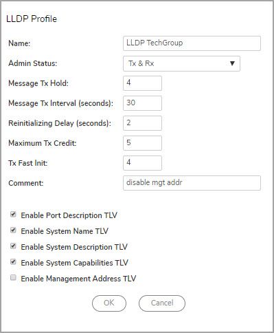
3 Click Add a new LLDP Profile. The Add LLDP Profile dialog displays.
4 In the Name field, enter a descriptive name for the LLDP profile.
5 From Admin Status, select transmission mode for the LLDP profile:
• Disabled
• Rx Only (default)
• Tx Only
• Tx & Rx
6 To change the message transmission interval to determine the value of the TTL value of the LLDP frames
transmitted by the LLDP agent, enter a multiplier in the Message Tx Hold field. The minimum value is 1,
the maximum is 100, and the default value is 4.
7 To define the time interval, in timer ticks, between transmissions during normal transmission periods,
enter the interval, in seconds, in the Message Tx Interval field. The minimum is 1 second, the maximum
is 3600 seconds, and the default is 30 seconds.
8 To specify the amount of delay from when Admin Status becomes Disabled until reinitialization can be
attempted again for the profile, enter the delay, in seconds, in the Reinitializing Delay field. The
SonicWall GMS 9.3 Administration Guide
33
Managing Layer 2 Discovery and LLDP/LLTDminimum is 1 second, the maximum is 10 seconds, and the default, and recommended delay, is 2
seconds.
9 To specify the maximum number of LLDPDUs that can be transmitted at any time for the LLDP profile,
enter the number in the Maximum Tx Credit field. The minimum is 1, the maximum is 10, and the default
is 5.
10 To specify an initial number of LLDPDUs transmitted during a fast transmission period, enter the number
in the Tx Fast Init field. The minimum is 1, the maximum is 8, and the default is 4.
11 Enter an optional comment in the Comment field. What you enter here displays when you mouse-over
the Information icon in the Comments column of the LLDP Profile table.
12 To include the port description of the Security Appliance in the optional TLV of a LLDPDU message, select
Enable Port Description TLV. This option is selected by default.
13 To include the configured Firewall Name of the Security Appliance in the optional TLV if a LLDPDU
message, select Enable System Name TLV. This option is selected by default.
14 To include Firewall as the identification of the Security Appliance in the optional TLV if a LLDPDU
message, select Enable System Description TLV. This option is selected by default.
15 To include an IPv4 or MAC address used for managing an interface of the Security Appliance in the
optional TLV if a LLDPDU message, select Enable Management Address TLV. This option is selected by
default.
16 Click OK. The name of the profile displays in the Profile Name column of the L2 Discovery table.
Editing a Custom LLDP Profile
TIP: Default LLDP Profiles cannot be edited.
To edit a custom LLDP profile:
1 Navigate to Switching > L2 Discovery.
2 Click LLDP Profile.
SonicWall GMS 9.3 Administration Guide
34
Managing Layer 2 Discovery and LLDP/LLTD3 Click the Edit icon for the profile. The Edit LLDP Profile dialog displays.
4 Make changes as necessary. For information about the options, see Adding an LLDP Custom Profile.
5 Click OK.
Deleting Custom Profiles
TIP: Default profiles cannot be deleted.
To delete a custom profile:
1 Navigate to Switching > L2 Discovery.
2 Click the LLDP Profile view.
3 Click the Delete icon for the profile. A confirmation message displays.
4 Click OK.
To delete one or more custom profiles:
1 Navigate to Switching > L2 Discovery.
2 Click the LLDP Profile view.
3 Select the profiles to be deleted.
4 Click Delete LLDP Profile(s). A confirmation message displays.
5 Click OK.
To delete all custom profiles:
1 Navigate to Switching > L2 Discovery.
SonicWall GMS 9.3 Administration Guide
35
Managing Layer 2 Discovery and LLDP/LLTD2 Click the LLDP Profile view.
3 Click the top checkbox in the left column heading. All custom profiles are selected.
4 Click Delete LLDP Profile(s). A confirmation message displays.
5 Click OK.
SonicWall GMS 9.3 Administration Guide
36
Managing Layer 2 Discovery and LLDP/LLTD6
Configuring Switch Shield
NOTE: Switching is available on all NSA 2650 and above firewalls.
To configure Switch Shield settings:
1 Navigate to Switching > Switch Shield.
2 Select the options for DDOS protection using switch capabilities. None of the options are selected by
default.
3 Click Update.
GMS Switching Administration Guide
37
Configuring Switch Shield7
SonicWall Support
Technical support is available to customers who have purchased SonicWall products with a valid maintenance
contract.
The Support Portal provides self-help tools you can use to solve problems quickly and independently, 24 hours a
day, 365 days a year. To access the Support Portal, go to https://www.sonicwall.com/support.
The Support Portal enables you to:
• View knowledge base articles and technical documentation
• View and participate in the Community forum discussions at
https://community.sonicwall.com/technology-and-support.
• View video tutorials
• Access MySonicWall
• Learn about SonicWall professional services
• Review SonicWall Support services and warranty information
• Register for training and certification
• Request technical support or customer service
To contact SonicWall Support, visit https://www.sonicwall.com/support/contact-support.
GMS Switching Administration Guide
38
SonicWall SupportAbout This Document
Legend
NOTE: A NOTE icon indicates supporting information.
IMPORTANT: An IMPORTANT icon indicates supporting information that may need a little extra attention.
TIP: A TIP indicates helpful information.
CAUTION: A CAUTION icon indicates potential damage to hardware or loss of data if instructions are not followed.
WARNING: A WARNING icon indicates a potential for property damage, personal injury, or death.
GMS Administration Guide
Updated - January 2021
Software Version - 9.3
232-005144-00 Rev B
Copyright © 2021 SonicWall Inc. All rights reserved.
The information in this document is provided in connection with SonicWall and/or its affiliates’ products. No license, express or implied, by
estoppel or otherwise, to any intellectual property right is granted by this document or in connection with the sale of products. EXCEPT AS
SET FORTH IN THE TERMS AND CONDITIONS AS SPECIFIED IN THE LICENSE AGREEMENT FOR THIS PRODUCT, SONICWALL AND/OR ITS
AFFILIATES ASSUME NO LIABILITY WHATSOEVER AND DISCLAIMS ANY EXPRESS, IMPLIED OR STATUTORY WARRANTY RELATING TO ITS
PRODUCTS INCLUDING, BUT NOT LIMITED TO, THE IMPLIED WARRANTY OF MERCHANTABILITY, FITNESS FOR A PARTICULAR PURPOSE, OR
NON-INFRINGEMENT. IN NO EVENT SHALL SONICWALL AND/OR ITS AFFILIATES BE LIABLE FOR ANY DIRECT, INDIRECT, CONSEQUENTIAL,
PUNITIVE, SPECIAL OR INCIDENTAL DAMAGES (INCLUDING, WITHOUT LIMITATION, DAMAGES FOR LOSS OF PROFITS, BUSINESS
INTERRUPTION OR LOSS OF INFORMATION) ARISING OUT OF THE USE OR INABILITY TO USE THIS DOCUMENT, EVEN IF SONICWALL AND/OR
ITS AFFILIATES HAVE BEEN ADVISED OF THE POSSIBILITY OF SUCH DAMAGES. SonicWall and/or its affiliates make no representations or
warranties with respect to the accuracy or completeness of the contents of this document and reserves the right to make changes to
specifications and product descriptions at any time without notice. and/or its affiliates do not make any commitment to update the
information contained in this document.
For more information, visit https://www.sonicwall.com/legal.
End User Product Agreement
To view the SonicWall End User Product Agreement, go to: https://www.sonicwall.com/legal/end-user-product-agreements/
Open Source Code
SonicWall is able to provide a machine-readable copy of open source code with restrictive licenses such as GPL, LGPL, AGPL when applicable
per license requirements. To obtain a complete machine-readable copy, send your written requests, along with certified check or money
order in the amount of USD 25.00 payable to “SonicWall Inc.”, to:
General Public License Source Code Request
SonicWall Inc. Attn: Jennifer Anderson
1033 McCarthy Blvd
Milpitas, CA 95035
GMS Switching Administration Guide
39
SonicWall SupportYou can also read