Technical Manual - EN - Faulhaber
←
→
Page content transcription
If your browser does not render page correctly, please read the page content below
Technical Manual

                   MC 3001 B/P

WE CREATE MOTION                      EN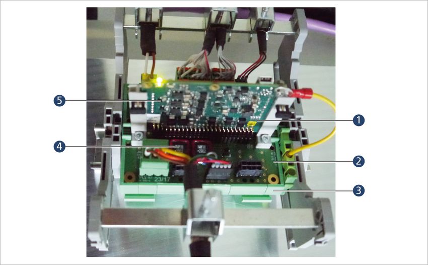
Imprint

                   Version:
                   2nd edition, 12.07.2021

                   Copyright
                   by Dr. Fritz Faulhaber GmbH & Co. KG
                   Daimlerstr. 23 / 25 · 71101 Schönaich

                   All rights reserved, including those to the translation.
                   No part of this description may be duplicated, reproduced,
                   stored in an information system or processed or
                   transferred in any other form without prior express written
                   permission of Dr. Fritz Faulhaber GmbH & Co. KG.

                   This document has been prepared with care.
                   Dr. Fritz Faulhaber GmbH & Co. KG cannot accept any
                   liability for any errors in this document or for the
                   consequences of such errors. Equally, no liability can be
                   accepted for direct or consequential damages resulting
                   from improper use of the equipment.

                   The relevant regulations regarding safety engineering
                   and interference suppression as well as the requirements
                   specified in this document are to be noted and followed
                   when using the software.

                   Subject to change without notice.

                   The respective current version of this technical manual is
                   available on FAULHABER's internet site:
                   www.faulhaber.com

2nd edition, 12.07.2021                                                   7000.05071, 2nd edition, 12.07.20217000.05071
                                                        2
Content
1 About this document ....................................................................................................... 5
1.1 Validity of this document ...................................................................................... 5
1.2 Associated documents ............................................................................................ 5
1.3 Using this document .............................................................................................. 5
1.4 List of abbreviations ............................................................................................... 6
1.5 Symbols and designations ...................................................................................... 7
2 Safety ................................................................................................................................ 8
2.1 Intended use ........................................................................................................... 8
2.2 Safety instructions .................................................................................................. 9
2.3 Environmental conditions ...................................................................................... 9
2.4 EC directives on product safety ........................................................................... 10
3 Product description ........................................................................................................ 11
3.1 General product description ................................................................................ 11
3.2 Product information ............................................................................................. 12
3.3 Product variants .................................................................................................... 13
3.3.1 Controller PCBs...................................................................................... 13
3.3.1.1 Standard PCB with micro board-to-board connectors
(MC3001 B) ............................................................................. 13
3.3.1.2 Standard PCB with plug connectors (MC 3001 P) ................ 17
3.3.2 Motherboards ....................................................................................... 20
3.3.2.1 Instructions for using other motherboards.......................... 20
3.3.2.2 Motherboard 6500.01802...................................................... 22
3.3.2.3 Motherboard 6500.01807...................................................... 29
3.3.2.4 Motherboard 6500.01808...................................................... 35
3.3.2.5 Motherboard 6500.01809...................................................... 40
3.3.2.6 Motherboard 6500.01810...................................................... 45
3.3.2.7 Motherboard 6500.01811...................................................... 50
4 Installation ...................................................................................................................... 55
4.1 Mounting .............................................................................................................. 55
4.1.1 Mounting instructions .......................................................................... 55
4.1.2 Installation of Motion Controller PCBs ................................................ 56
4.2 Electrical connection ............................................................................................ 57
4.2.1 Notes on the electrical connection ...................................................... 57
4.2.2 Drive connections.................................................................................. 58
4.2.3 Connection of the power supply ......................................................... 59
4.2.3.1 Power supply.......................................................................... 59
4.2.4 I/O circuit diagrams ............................................................................... 60
4.2.5 External circuit diagrams ...................................................................... 62
4.3 Electromagnetic compatibility (EMC) .................................................................. 65
4.3.1 Considered systems ............................................................................... 65
4.3.2 Functional earthing .............................................................................. 67
4.3.3 Cable routing ........................................................................................ 67
4.3.4 Shielding ................................................................................................ 69
4.3.4.1 Establishing the shield connection ....................................... 70
4.3.4.2 Establishing shield connection with cable lug ..................... 71
2nd edition, 12.07.2021 7000.05071, 2nd edition, 12.07.20217000.05071
3Content
4.3.5 Sensor and encoder interfaces ............................................................. 72
4.3.5.1 Analogue sensors and analogue Hall sensors ...................... 73
4.3.5.2 Incremental encoders / Digital Hall sensors /
Digital sensors ........................................................................ 73
4.3.5.3 Encoders with absolute interface ......................................... 73
4.3.6 Using filters ........................................................................................... 73
4.3.6.1 EMC-compliant mounting of the Motion Controller with
motherboard.......................................................................... 74
4.3.6.2 PWM filter (motor-side) ........................................................ 74
4.3.6.3 Emission-reducing, ferrite-based filters (motor side) .......... 74
4.3.6.4 Input-side filters..................................................................... 75
4.3.6.5 Insulation resistance .............................................................. 75
4.3.6.6 Coiling ferrite ring ................................................................. 75
4.3.7 Error avoidance and troubleshooting ................................................. 76
5 Maintenance and diagnostics ........................................................................................ 78
5.1 Maintenance tasks ................................................................................................ 78
5.2 Diagnosis ............................................................................................................... 78
5.3 Troubleshooting ................................................................................................... 78
6 Accessories ...................................................................................................................... 79
7 Warranty ......................................................................................................................... 80
8 Additional documents .................................................................................................... 81
8.1 Declaration of Conformity ................................................................................... 81
8.2 Declaration of Incorporation ............................................................................... 83
2nd edition, 12.07.2021 7000.05071, 2nd edition, 12.07.20217000.05071
4About this document
1 About this document
1.1 Validity of this document
This document describes the installation and use of the FAULHABER MC 3001 series.
This document is intended for use by trained experts authorised to perform installation and
electrical connection of the product.
All data in this document relate to the standard versions of the series listed above. Changes
relating to customer-specific versions can be found in the corresponding data sheet.
1.2 Associated documents
For certain actions during commissioning and operation of FAULHABER products additional
information from the following manuals is useful:
Manual Description
Motion Manager 6 Operating instructions for FAULHABER Motion Manager PC software
Quick start guide Description of the first steps for commissioning and operation of FAULHABER Motion
Controllers
Drive functions Description of the operating modes and functions of the drive
Accessories manual Description of the accessories
These manuals can be downloaded in pdf format from the web page
www.faulhaber.com/manuals.
1.3 Using this document
Read the document carefully before undertaking configuration, in particular chapter
“Safety”.
Retain the document throughout the entire working life of the product.
Keep the document accessible to the operating and, if necessary, maintenance person-
nel at all times.
Pass the document on to any subsequent owner or user of the product.
2nd edition, 12.07.2021 7000.05071, 2nd edition, 12.07.20217000.05071
5About this document
1.4 List of abbreviations
Abbreviation Meaning
AC Alternating Current
AES Absolute encoder
AGND Analogue Ground
AnIn Analogue input
CAN Controller Area Network
CAN_L CAN-Low
CAN_H CAN-High
CLK Clock
CS Chip Select
DigIn Digital input
DigOut Digital output
EFM Electronics Filter Motor
EFS Electronics Filter Supply
EMC Electromagnetic compatibility
ESD Electrostatic discharge
GND Ground
I/O Input/Output
MC Motion Controller
Mot Motor
n.c. not connected
PWM Pulse Width Modulation
RxD Receive Data
SGND Signal ground
TxD Transmit data
2nd edition, 12.07.2021 7000.05071, 2nd edition, 12.07.20217000.05071
6About this document
1.5 Symbols and designations
CAUTION!
Hazards due to hot surfaces. Disregard may lead to burns.
Measures for avoidance
NOTICE!
Risk of damage.
Measures for avoidance
Instructions for understanding or optimising the operational procedures
Pre-requirement for a requested action
1. First step for a requested action
Result of a step
2. Second step of a requested action
Result of an action
Request for a single-step action
2nd edition, 12.07.2021 7000.05071, 2nd edition, 12.07.20217000.05071
7Safety
2 Safety
2.1 Intended use
The Motion Controllers described here are designed for use as slaves for control and posi-
tioning tasks for the following motors:
DC-Micromotors
Linear DC-Servomotors
Brushless DC-motors
The Motion Controller is suitable in particular for tasks in the following fields of applica-
tion:
Robotics
Toolbuilding
Automation technology
Industrial equipment and special machine building
Medical technology
Laboratory technology
When using the Motion Controllers the following aspects should be observed:
The Motion Controller contains electronic components and should be handled in
accordance with the ESD regulations.
Do not use the Motion Controller in environments where it will come into contact with
water, chemicals and/or dust, nor in explosion hazard areas.
The Motion Controller is not suitable for use in combination with stepper motors.
The Motion Controller should be operated only within the limits specified in the data
sheet.
Please ask the manufacturer for information about use under individual special
environmental conditions.
2nd edition, 12.07.2021 7000.05071, 2nd edition, 12.07.20217000.05071
8Safety
2.2 Safety instructions
NOTICE!
Electrostatic discharges can damage the electronics.
Wear conductive work clothes.
Wear an earthed wristband.
NOTICE!
Foreign bodies can damage the electronics.
Keep foreign objects away from the electronics.
NOTICE!
Inserting and withdrawing connectors whilst supply voltage is applied at the device can
damage the electronics.
Do not insert or withdraw connectors whilst supply voltage is applied at the device.
2.3 Environmental conditions
Select the installation location so that clean dry air is available for cooling the Motion
Controller.
Select the installation location so that the air has unobstructed access to flow around
the drive.
When installed within housings and cabinets take particular care to ensure adequate
cooling of the Motion Controller.
Select a power supply that is within the defined tolerance range.
Protect the Motion Controller against heavy deposits of dust, in particular metal dust
and chemical pollutants.
Protect the Motion Controller against humidity and wet.
2nd edition, 12.07.2021 7000.05071, 2nd edition, 12.07.20217000.05071
9Safety
2.4 EC directives on product safety
The following EC directives on product safety must be observed.
If the Motion Controller is being used outside the EU, international, national and
regional directives must be also observed.
Machinery Directive (2006/42/EC)
The controllers with attached motor described in these installation instructions may be
drive systems according to the Machinery Directive. They are therefore to be considered
incomplete machines according to the Machinery Directive. Compliance is documented by
the Declaration of Incorporation for the product and by the EC Declaration of the Conform-
ity.
EMC Directive (2014/30/EU)
The directive concerning electromagnetic compatibility (EMC) applies to all electrical and
electronic devices, installations and systems sold to an end user. In addition, CE marking can
be undertaken for built-in components according to the EMC Directive. Conformity with
the directive is documented in the Declaration of Conformity.
Applied standards
Various harmonised standards were applied to the products described in this technical
manual; these standards are documented in the EC Declaration of Conformity. You can find
the Declaration of Incorporation for the product and the EC Declaration of Conformity in
chap. 8, p. 81.
2nd edition, 12.07.2021 7000.05071, 2nd edition, 12.07.20217000.05071
10Product description
3 Product description
3.1 General product description
The MC 3001 products are unhoused versions of the FAULHABER Motion Controllers and
control either DC, LM or BL motors. The Motion Controllers are configured here via the
FAULHABER Motion Manager software V6 (version 6.7 and higher).
The drives can be operated in the network via the CANopen fieldbus interface. The Motion
Controller operates in the network in principle as a slave; master functionality for actuating
other axes is not provided. After basic commissioning via Motion Manager, the controllers
can alternatively also be operated without communication interface.
The controllers can be plugged into a motherboard via 3 micro board-to-board connectors
(MC 3001 B) or a 28-pin plug connector (MC 3001 P).
With the integrated output stage with optimised current measurement, DC, BL and LM
motors from the FAULHABER product line from 06 to 30 mm can be controlled.
The following connections are available on the connector strip:
Communications interfaces
Common or separate power supplies between motor and controller
Various inputs and outputs
Motor phases
Feedback components such as:
Digital/analogue Hall sensors
Incremental encoders with or without line drivers.
Motion Controllers with RS232 or CANopen interface can also be operated inde-
pendently of the communication interface if a function or a suitable sequence pro-
gram was previously stored locally.
2nd edition, 12.07.2021 7000.05071, 2nd edition, 12.07.20217000.05071
11Product description
3.2 Product information
MC … … … …
RS: Serial interface RS232
CO: Interface CANopen
P: PCB version with pin terminals
B: PCB version with micro board-to-board connectors
01: Max. continuous output current 1 A
30: Max. power supply 30 V
MC: Motion Controller
Fig. 1: Designation key
2nd edition, 12.07.2021 7000.05071, 2nd edition, 12.07.20217000.05071
12Product description
3.3 Product variants
The following product variants are possible:
MC 3001 B RS/CO
MC 3001 P RS/CO
The Motion Controller PCBs can be mounted on a motherboard. The FAULHABER mother-
board offers space for a Motion Controller PCB.
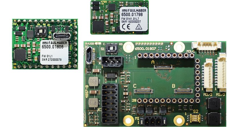
3.3.1 Controller PCBs
3.3.1.1 Standard PCB with micro board-to-board connectors (MC3001 B)
Status LED
C B
A
Fig. 2: Isometric view (left) and rear view (right) of the standard PCB with micro board-to-
board connectors
State LED
Tab. 1: LED function
LED indicator Function
Green (continuous Device active.
light)
Green (flashing) Device active. However the state machine has not yet reached the Operation Enabled
state.
Red (continuously The drive has switched to a fault state. The output stage will be switched off or has
flashing) already been switched off.
Red (error code) Boot procedure failed. Please contact FAULHABER Support.
2nd edition, 12.07.2021 7000.05071, 2nd edition, 12.07.20217000.05071
13Product description
Pin assignment of the connector
The MC 3001 B Motion Controller has 3 connectors by means of which the connection
between Motion Controller and motherboard or customer-specific peripherals is estab-
lished.
34 18 34 18
36 35 36 35
C B
1 17 1 17
34 18
A
36 35
1 17
Fig. 3: Pin overview of the micro board-to-board connectors of the MC 3001 B
For technical data, see motherboard pin assignment.
Tab. 2: Pin assignment of connector A
Pin Designation Meaning
1 GND Ground connection
2, 3 Up Power supply of the electronics
4 CAN-L CAN-Low interface
5 CAN-H CAN-High interface
6 GND Ground connection
7 Reserved Do not connect
8 GND Ground connection
9 UDD 5V supply connection for sensors
10 DigIn 1 Digital input
11 DigIn 2 Digital input
12 DigIn 3 Digital input
13 DigOut 1 Digital output
14 DigOut 2 Digital output
15 TxD RS232 interface transmit direction
16 RxD RS232 interface receive direction
17, 18 EGND Earth connection
19 USB ID USB port ID
20 USB D+ USB port D+
21 USB D– USB port D–
2nd edition, 12.07.2021 7000.05071, 2nd edition, 12.07.20217000.05071
14Product description
Pin Designation Meaning
22 USB VCC USB port VCC
23…31 Reserved Do not connect
32, 33 Up Power supply of the electronics
34, 35 GND Ground connection
36 Umot Power supply of the motor
Tab. 3: Pin assignment of connector B
Pin Designation Meaning
1 UDD 5V supply connection for sensors
2…4 GND Ground connection
5…7 Reserved Do not connect
8 n.c. –
9 AnIn 1 Analogue input
10 AGND Analogue ground connection
11 AnIn 2 Analogue input
12, 13 n.c. –
14…16 GND Ground connection
17 Reserved Do not connect
18 GND Ground connection
19 Channel A Encoder channel A (logically inverted signal)
20 Channel B Encoder channel B (logically inverted signal)
21 Index Index channel (logically inverted signal)
22 Index Index channel
23 Channel B Encoder channel B
24 Channel A Encoder channel A
25, 26 Reserved Do not connect
27 Sens A Hall sensor A
28 Sens B Hall sensor B
29 Sens C Hall sensor C
30…33 GND Ground connection
34 UDD 5V supply connection for sensors
35 GND Ground connection
36 UDD 5V supply connection for sensors
2nd edition, 12.07.2021 7000.05071, 2nd edition, 12.07.20217000.05071
15Product description
Tab. 4: Pin assignment of connector C
Pin Designation Meaning
1 n.c. –
2…5 Reserved Do not connect
6…9 GND Ground connection
10…13 Phase B Motor phase B
14…17 GND Ground connection
18…28 Phase B Motor phase B
29…34 Reserved Do not connect
35 Phase C Motor phase C
36 Phase A Motor phase A
The motor phase B signal is assigned multiple times to achieve sufficient current-carry-
ing capacity. For the motor phase A and motor phase C connections, multiple assign-
ment is not necessary since sufficient current-carrying capacity is achieved at pin 35 and
pin 36 due to the design of the connector.
2nd edition, 12.07.2021 7000.05071, 2nd edition, 12.07.20217000.05071
16Product description
3.3.1.2 Standard PCB with plug connectors (MC 3001 P)
Status LED Status LED
USB (X1)
USB (X1)
Fig. 4: Isometric view (left) and top view (right) of the standard PCB with plug connectors
State LED
Tab. 5: LED function
LED indicator Function
Green (continuous Device active.
light)
Green (flashing) Device active. However the state machine has not yet reached the Operation Enabled
state.
Red (continuously The drive has switched to a fault state. The output stage will be switched off or has
flashing) already been switched off.
Red (error code) Boot procedure failed. Please contact FAULHABER Support.
USB (X1)
Connection of the USB communication (USB micro B).
2nd edition, 12.07.2021 7000.05071, 2nd edition, 12.07.20217000.05071
17Product description
Pin assignment of the plug connector
The MC 3001 P Motion Controller has a connector strip by means of which the connection
between Motion Controller and motherboard or customer-specific peripherals is estab-
lished.
1 10
11
28 19
Fig. 5: Pin overview of the plug connector of the MC 3001 P
For technical data, see motherboard pin assignment.
Tab. 6: Pin assignment of the plug connector
Pin Designation Meaning
1 GND Ground connection
2 Umot Power supply of the motor
3 Up Power supply of the electronics
4 CAN-H CAN-High interface
TxD RS232 interface transmit direction
5 CAN-L CAN-Low interface
RxD RS232 interface receive direction
6 DigIn 1 Digital input
7 DigIn 2 Digital input
8 DigIn 3 Digital input
9 DigOut 1 Digital output
10 DigOut 2 Digital output
11 EGND Earth connection
12 GND Ground connection
13 AnIn 1 Analogue input
14 AGND Analogue ground connection
15 AnIn 2 Analogue input
16 Channel A Encoder channel A (logically inverted signal)
17 Channel B Encoder channel B (logically inverted signal)
2nd edition, 12.07.2021 7000.05071, 2nd edition, 12.07.20217000.05071
18Product description
Pin Designation Meaning
18 Index Index channel (logically inverted signal)
19 Index Index channel
20 Channel B Encoder channel B
21 Channel A Encoder channel A
22 Sens C Hall sensor C
23 Sens B Hall sensor B
24 Sens A Hall sensor A
25 UDD 5V supply connection for sensors
26 Phase C Motor phase C
27 Phase B Motor phase B
28 Phase A Motor phase A
2nd edition, 12.07.2021 7000.05071, 2nd edition, 12.07.20217000.05071
19Product description
3.3.2 Motherboards
The following motherboards are available and each support both products MC 3001 B and
MC 3001 P:
Tab. 7: Available motherboards from FAULHABER
Option Description Reference
6500.01802 MB1 MC 3001 for general combination with BL/DC-motors including Hall chap. 3.3.2.2, p. 22
sensors and/or encoders
6500.01807 MB1 MC 3001 for combination with DC-motors and encoders IE2, IEH2, chap. 3.3.2.3, p. 29
IEH3(L)
6500.01808 MB1 MC 3001 for combination with DC-motors and encoders IE3(L), chap. 3.3.2.4, p. 35
IER3(L), IERS3(L)
6500.01809 MB1 MC 3001 for combination with DC-motors and encoders PA2-100, chap. 3.3.2.5, p. 40
HEM3
6500.01810 MB1 MC 3001 for combination with BL-motors and encoders AESM, IEM3 chap. 3.3.2.6, p. 45
6500.01811 MB1 MC 3001 for combination with BL/DC-motors and encoders PA2-50, chap. 3.3.2.7, p. 50
HXM
When using other motherboards, observe the instructions in chap. 3.3.2.1, p. 20.
3.3.2.1 Instructions for using other motherboards
If motherboards other than those offered by FAULHABER are used (see Tab. 7), they
must be manufactured in accordance with the following guidelines:
PCB: IPC-A-600H Class 2
Mounting/soldering: IPC-A-600E Class 2
The following sockets are recommended as counterparts to the controller connectors:
MC 3001 P
Manufacturer:W+P
Series: Socket Strip 10 (2 pieces)
Details: 10-pin, contact spacing 2.54, gold-plated
Manufacturer 153-010-1-50-00
number:
Manufacturer:W+P
Series: Socket Strip 10 (1 piece)
Details: 8-pin, contact spacing 2.54, gold-plated
Manufacturer 153-008-1-50-00
number:
For each MC 3001 P, 2x 10-pin sockets and 1x 8-pin socket are needed.
2nd edition, 12.07.2021 7000.05071, 2nd edition, 12.07.20217000.05071
20Product description
MC 3001 B
Manufacturer:Molex
Series: Slim Stack
Details: 34-pin + 2-pin edge contact, contact spacing 0.35 mm, gold-plated
Manufacturer 505413-3410
number:
For each MC 3001 B, 3 sockets are needed.
Also observe the dimensions and tolerances shown in the following figures.
1.28 ± 0.03 B ± 0.03
0.18 ± 0.03
0.35 ± 0.03
± 0.03
0.4 ± 0.03
(PITCH)
± 0.03
0.385
0.58
± 0.03
1.5
6
6 0.3 MAX.
6
0.4 ± 0.03 (B+0.53)MIN.
1.28 mm
18 34
35 36
1.9 mm 0.965 mm
35 0.35 mm 36
17 1
Pads 35, 36: 0.4 x 0.385 mm Pads 1...34: 0.18 x 0.4 mm
Fig. 6: Dimensions and tolerances of the sockets for controller connectors A, B and C
2nd edition, 12.07.2021 7000.05071, 2nd edition, 12.07.20217000.05071
21Product description
3.3.2.2 Motherboard 6500.01802
With this motherboard, it is possible to combine FAULHABER BL/DC-motors as well as Hall
sensors and/or encoders.
65
X1
S1 1
1
1
X2 MC M3
A 2 1
40
2 1 C B
28
1
S2
X3
1 1
M1 M2
Fig. 7: Side view (top), top view (middle) and isometric view (bottom) of the
motherboard 6500.01802
2nd edition, 12.07.2021 7000.05071, 2nd edition, 12.07.20217000.05071
22Product description
Tab. 8: Connector overview of the motherboard 6500.01802
Designation Function
A, B, C (controller) MC 3001 B connection (for pin assignment, see chap. 3.3.1.1, p. 13)
MC (controller) MC 3001 P connection (for pin assignment, see chap. 3.3.1.2, p. 17)
M1 (motor) Connection of the motor phases
M2 (sensor) Connection of the Hall sensors
M3 (encoder) Connection of an incremental encoder with or without line driver
Alternatively an absolute encoder can be connected with or without line driver
X1 (USB) USB interface connection
X2 (COM) CAN/RS232 interface connection
X3 (I/O) Voltage supply of the controller and motor
Inputs or outputs for external circuits
S1 (DIP switch COM) Selection of the COM interface:
C: CAN
RS: RS232
S2 (DIP Switch Encoder Term) Encoder terminal resistance:
Encoder without line driver: S2-1, S2-2 and S2-3 in OFF position
Encoder with line driver (L version): S2-1, S2-2 and S2-3 in ON position
Motor connection (M1)
Tab. 9: Pin assignment of the BL motor connection (M1)
Pin Designation Meaning
1 Motor A Connection of motor, phase A
2 Motor B Connection of motor, phase B
3 Motor C Connection of motor, phase C
Tab. 10: Electrical data of the motor connection (M1)
Designation Value
Motor power supply 0...Umot
Max. 5 A
100 kHz
2nd edition, 12.07.2021 7000.05071, 2nd edition, 12.07.20217000.05071
23Product description
Tab. 11: Pin assignment of the DC motor connection (M1)
Pin Designation Meaning
1 Motor + Connection of motor, positive pole
2 Motor – Connection of the motor, negative pole
Tab. 12: Electrical data of the DC motor connection (M1)
Designation Value
Motor power supply 0...Umot
Max. 5 A
100 kHz
Sensor connection (M2)
Tab. 13: Pin assignment at sensor connection (M2) for 3 Hall sensor signals
Pin Designation Meaning
1 UDD Power supply for sensors
2 GND Ground connection
3 Sens A Hall sensor A
4 Sens B Hall sensor B
5 Sens C Hall sensor C
Tab. 14: Pin assignment at sensor connection (M2) for sin/cos sensor
Pin Designation Meaning
1 UDD Power supply for sensors
2 GND Ground connection
3 COS(+) Cosine signal
4 SIN(+) Sine signal
5 n.c. –
Tab. 15: Electrical data of the sensor connection (M2)
Designation Value
Sensor power supply 5VProduct description
Encoder connection (M3)
The pin assignment of the encoder connector varies depending on the encoder type.
Incremental encoder with or without line driver
Absolute encoder with or without line driver.
Tab. 16: Pin assignment for incremental encoder with line driver (M3)
Pin Designation Meaning
1 UDD Power supply for incremental encoder
2 GND Ground connection
3 Channel A Encoder channel A (logically inverted sig-
nal)
4 Channel A Encoder channel A
5 Channel B Encoder channel B (logically inverted sig-
nal)
6 Channel B Encoder channel B
7 Index Encoder index (logically inverted signal)
8 Index Encoder index
Tab. 17: Electrical data for incremental encoder with line driver (M3)
Designation Value
Power supply for incremental 5V
encoderProduct description
Tab. 19: Electrical data for incremental encoder without line driver (M3)
Designation Value
Power supply for incremental 5V
encoderProduct description
Tab. 23: Electrical data for absolute encoder without line driver (M3)
Designation Value
Absolute encoder power supply 5VProduct description
I/O connection (X3)
Tab. 27: Pin assignment of the I/O connection (X3)
Pin Designation Meaning
1 UDD Power supply for external consumer loads
1 3 5 7 9 11 13
2 GND Ground connection
3 DigOut 1 Digital output (open collector)
4 DigOut 2 Digital output (open collector)
5 DigIn 1 Digital input
6 DigIn 2 Digital input
2 4 6 8 10 12 14
7 DigIn 3 Digital input
8 AnIn 1 Analogue input
9 AnIn 2 Analogue input
10 AGND Ground connection for analogue inputs
11 Up Power supply of the electronics
12 GND Ground connection
13 Umot Power supply of the motor
14 GND Ground connection
Tab. 28: Electrical data for the I/O connection (X3)
Designation Value
Power supply for external consum- 5V
ersProduct description
3.3.2.3 Motherboard 6500.01807
With this motherboard, FAULHABER DC-motors can be combined with encoders of types
IE2, IEH2 or IEH3(L). Motor connections M+ and M– can be connected here either via con-
nector M1 or, with combined cables, via connector M3.
65
X1 M3/1
S1 1
1
1
1
X2 MC
A
40
2 1 1 1
C B
M3/2 M3/3
28
X3 1
1
M1 S2
Fig. 8: Side view (top), top view (middle) and isometric view (bottom) of the
motherboard 6500.01807
2nd edition, 12.07.2021 7000.05071, 2nd edition, 12.07.20217000.05071
29Product description
Tab. 29: Connector overview of the motherboard 6500.01807
Designation Function
A, B, C (controller) MC 3001 B connection (for pin assignment, see chap. 3.3.1.1, p. 13)
MC (controller) MC 3001 P connection (for pin assignment, see chap. 3.3.1.2, p. 17)
M1 (motor) Connection of the motor phases
M3/1 (motor and encoder) Connection of a motor with IE2 incremental encoder
M3/2 (motor and encoder) Connection of a motor with IEH3 incremental encoder
M3/3 (motor and encoder) Connection of a motor with IEH3L incremental encoder
X1 (USB) USB interface connection
X2 (COM) CAN/RS232 interface connection
X3 (I/O) Voltage supply of the controller and motor
Inputs or outputs for external circuits
S1 (DIP switch COM) Selection of the COM interface:
C: CAN
RS: RS232
S2 (DIP Switch Encoder Term) Encoder terminal resistance:
Encoder without line driver: S2-1, S2-2 and S2-3 in OFF position
Encoder with line driver (L version): S2-1, S2-2 and S2-3 in ON position
Motor connection (M1)
Tab. 30: Pin assignment of the DC motor connection (M1)
Pin Designation Meaning
1 Motor + Connection of motor, positive pole
2 Motor – Connection of the motor, negative pole
Tab. 31: Electrical data of the DC motor connection (M1)
Designation Value
Motor power supply 0...Umot
Max. 5 A
100 kHz
2nd edition, 12.07.2021 7000.05071, 2nd edition, 12.07.20217000.05071
30Product description
Motor and IE2 encoder connection (M3/1)
Tab. 32: Pin assignment of the motor and IE2 encoder connection (M3/1)
Pin Designation Meaning
1 Motor – Connection of the motor, negative pole
6 5 4 3 2 1 2 Motor + Connection of motor, positive pole
3 GND Ground connection
4 UDD Power supply for incremental encoder
5 Channel B Encoder channel B
6 Channel A Encoder channel A
Tab. 33: Electrical data of the motor and IE2 encoder connection (M3/1)
Designation Value
Motor power supply 0...Umot
Max. 1 A
100 kHz
Power supply for incremental 5V
encoderProduct description
Motor and IEH3L encoder connection (M3/3)
Tab. 36: Pin assignment of the motor and IEH3L encoder connection (M3/3)
Pin Designation Meaning
1 Motor – Connection of the motor, negative pole
9 7 5 3 1 2 UDD Power supply for incremental encoder
3 GND Ground connection
4 Motor + Connection of motor, positive pole
5 Channel A Encoder channel A (logically inverted sig-
nal)
10 8 6 4 2 6 Channel A Encoder channel A
7 Channel B Encoder channel B (logically inverted sig-
nal)
8 Channel B Encoder channel B
9 Index Encoder index (logically inverted signal)
10 Index Encoder index
Tab. 37: Electrical data of the motor and IEH3L encoder connection (M3/3)
Designation Value
Motor power supply 0...Umot
Max. 1 A
100 kHz
Power supply for incremental 5V
encoderProduct description
COM port (X2)
The pin assignment of the COM connection differs according to the type of communication.
The distinction is made between the following types of communication:
RS232
CANopen
Tab. 39: Pin assignment of the COM port (X2) for RS232
Pin Designation Meaning
1 TxD RS232 interface transmit direction
2 RxD RS232 interface receive direction
3 GND Ground connection
Tab. 40: Pin assignment of the COM port (X2) for CANopen
Pin Designation Meaning
1 CAN-H CAN-High interface
2 CAN-L CAN-Low interface
3 GND Ground connection
2nd edition, 12.07.2021 7000.05071, 2nd edition, 12.07.20217000.05071
33Product description
I/O connection (X3)
Tab. 41: Pin assignment of the I/O connection (X3)
Pin Designation Meaning
1 UDD Power supply for external consumer loads
1 3 5 7 9 11 13
2 GND Ground connection
3 DigOut 1 Digital output (open collector)
4 DigOut 2 Digital output (open collector)
5 DigIn 1 Digital input
6 DigIn 2 Digital input
2 4 6 8 10 12 14
7 DigIn 3 Digital input
8 AnIn 1 Analogue input
9 AnIn 2 Analogue input
10 AGND Ground connection for analogue inputs
11 Up Power supply of the electronics
12 GND Ground connection
13 Umot Power supply of the motor
14 GND Ground connection
Tab. 42: Electrical data for the I/O connection (X3)
Designation Value
Power supply for external consum- 5V
ersProduct description
3.3.2.4 Motherboard 6500.01808
With this motherboard, FAULHABER DC-motors can be combined with encoders of types
IE3(L), IER3(L) or IERS3(L).
65
X1 M3/1
S1 1
1
1
X2 MC
1
A
40
2 1 C B
28
1
X3 1
1
M1 S2 M3/2
Fig. 9: Side view (top), top view (middle) and isometric view (bottom) of the
motherboard 6500.01808
2nd edition, 12.07.2021 7000.05071, 2nd edition, 12.07.20217000.05071
35Product description
Tab. 43: Connector overview of the motherboard 6500.01808
Designation Function
A, B, C (controller) MC 3001 B connection (for pin assignment, see chap. 3.3.1.1, p. 13)
MC (controller) MC 3001 P connection (for pin assignment, see chap. 3.3.1.2, p. 17)
M1 (motor) Connection of the motor phases
M3/1 (encoder) Connection of an IE3 incremental encoder
M3/2 (encoder) Connection of an IE3L incremental encoder
X1 (USB) USB interface connection
X2 (COM) CAN/RS232 interface connection
X3 (I/O) Voltage supply of the controller and motor
Inputs or outputs for external circuits
S1 (DIP switch COM) Selection of the COM interface:
C: CAN
RS: RS232
S2 (DIP Switch Encoder Term) Encoder terminal resistance:
Encoder without line driver: S2-1, S2-2 and S2-3 in OFF position
Encoder with line driver (L version): S2-1, S2-2 and S2-3 in ON position
Motor connection (M1)
Tab. 44: Pin assignment of the DC motor connection (M1)
Pin Designation Meaning
1 Motor + Connection of motor, positive pole
2 Motor – Connection of the motor, negative pole
Tab. 45: Electrical data of the DC motor connection (M1)
Designation Value
Motor power supply 0...Umot
Max. 5 A
100 kHz
2nd edition, 12.07.2021 7000.05071, 2nd edition, 12.07.20217000.05071
36Product description
IE3 encoder connection (M3/1)
Tab. 46: Pin assignment of the IE3 encoder connection (M3/1)
Pin Designation Meaning
1 – n.c.
6 5 4 3 2 1 2 Index Encoder index
3 GND Ground connection
4 UDD Power supply for incremental encoder
5 Channel B Encoder channel B
6 Channel A Encoder channel A
Tab. 47: Electrical data of the IE3 encoder connection (M3/1)
Designation Value
Power supply for incremental 5V
encoderProduct description
USB (X1)
Tab. 50: USB port
Designation Meaning
USB communication (USB micro B)
COM port (X2)
The pin assignment of the COM connection differs according to the type of communication.
The distinction is made between the following types of communication:
RS232
CANopen
Tab. 51: Pin assignment of the COM port (X2) for RS232
Pin Designation Meaning
1 TxD RS232 interface transmit direction
2 RxD RS232 interface receive direction
3 GND Ground connection
Tab. 52: Pin assignment of the COM port (X2) for CANopen
Pin Designation Meaning
1 CAN-H CAN-High interface
2 CAN-L CAN-Low interface
3 GND Ground connection
2nd edition, 12.07.2021 7000.05071, 2nd edition, 12.07.20217000.05071
38Product description
I/O connection (X3)
Tab. 53: Pin assignment of the I/O connection (X3)
Pin Designation Meaning
1 UDD Power supply for external consumer loads
1 3 5 7 9 11 13
2 GND Ground connection
3 DigOut 1 Digital output (open collector)
4 DigOut 2 Digital output (open collector)
5 DigIn 1 Digital input
6 DigIn 2 Digital input
2 4 6 8 10 12 14
7 DigIn 3 Digital input
8 AnIn 1 Analogue input
9 AnIn 2 Analogue input
10 AGND Ground connection for analogue inputs
11 Up Power supply of the electronics
12 GND Ground connection
13 Umot Power supply of the motor
14 GND Ground connection
Tab. 54: Electrical data for the I/O connection (X3)
Designation Value
Power supply for external consum- 5V
ersProduct description
3.3.2.5 Motherboard 6500.01809
With this motherboard, FAULHABER DC-motors can be combined with encoders of types
PA2-100 or HEM3.
65
X1 M3/1
S1 1
1
1
X2 MC
1
A
40
2 1 C B
M3/2
28
X3
Fig. 10: Side view (top), top view (middle) and isometric view (bottom) of the
motherboard 6500.01809
2nd edition, 12.07.2021 7000.05071, 2nd edition, 12.07.20217000.05071
40Product description
Tab. 55: Connector overview of the motherboard 6500.01809
Designation Function
A, B, C (controller) MC 3001 B connection (for pin assignment, see chap. 3.3.1.1, p. 13)
MC (controller) MC 3001 P connection (for pin assignment, see chap. 3.3.1.2, p. 17)
M3/1 (motor and encoder) Connection of a motor with HEM3 incremental encoder
M3/2 (motor and encoder) Connection of a motor with PA2-100 incremental encoder
X1 (USB) USB interface connection
X2 (COM) CAN/RS232 interface connection
X3 (I/O) Voltage supply of the controller and motor
Inputs or outputs for external circuits
S1 (DIP switch COM) Selection of the COM interface:
C: CAN
RS: RS232
Motor and HEM3 encoder connection (M3/1)
Tab. 56: Pin assignment of the motor and HEM3 encoder connection (M3/1)
Pin Designation Meaning
1 Motor – Connection of the motor, negative pole
7 5 3 1 2 GND Ground connection
3 UDD Power supply for incremental encoder
4 – n.c.
5 Channel B Encoder channel B
6 Channel A Encoder channel A
8 6 4 2
7 Index Encoder index
8 Motor + Connection of motor, positive pole
Tab. 57: Electrical data of the motor and HEM3 encoder connection (M3/1)
Designation Value
Motor power supply 0...Umot
Max. 1 A
100 kHz
Power supply for incremental 5V
encoderProduct description
Motor and PA2-100 encoder connection (M3/2)
Tab. 58: Pin assignment of the motor and PA2-100 encoder connection (M3/2)
Pin Designation Meaning
1 Motor + Connection of motor, positive pole
1 3 5 7 2 Motor + Connection of motor, positive pole
3 UDD Power supply for incremental encoder
4 Channel A Encoder channel A
5 Channel B Encoder channel B
2 4 6 8
6 GND Ground connection
7 Motor – Connection of the motor, negative pole
8 Motor – Connection of the motor, negative pole
Tab. 59: Electrical data of the motor and PA2-100 encoder connection (M3/2)
Designation Value
Motor power supply 0...Umot
Max. 1 A
100 kHz
Power supply for incremental 3,3 V
encoderProduct description
COM port (X2)
The pin assignment of the COM connection differs according to the type of communication.
The distinction is made between the following types of communication:
RS232
CANopen
Tab. 61: Pin assignment of the COM port (X2) for RS232
Pin Designation Meaning
1 TxD RS232 interface transmit direction
2 RxD RS232 interface receive direction
3 GND Ground connection
Tab. 62: Pin assignment of the COM port (X2) for CANopen
Pin Designation Meaning
1 CAN-H CAN-High interface
2 CAN-L CAN-Low interface
3 GND Ground connection
2nd edition, 12.07.2021 7000.05071, 2nd edition, 12.07.20217000.05071
43Product description
I/O connection (X3)
Tab. 63: Pin assignment of the I/O connection (X3)
Pin Designation Meaning
1 UDD Power supply for external consumer loads
1 3 5 7 9 11 13
2 GND Ground connection
3 DigOut 1 Digital output (open collector)
4 DigOut 2 Digital output (open collector)
5 DigIn 1 Digital input
6 DigIn 2 Digital input
2 4 6 8 10 12 14
7 DigIn 3 Digital input
8 AnIn 1 Analogue input
9 AnIn 2 Analogue input
10 AGND Ground connection for analogue inputs
11 Up Power supply of the electronics
12 GND Ground connection
13 Umot Power supply of the motor
14 GND Ground connection
Tab. 64: Electrical data for the I/O connection (X3)
Designation Value
Power supply for external consum- 5V
ersProduct description
3.3.2.6 Motherboard 6500.01810
With this motherboard, FAULHABER 0824B- and 1028B-BL-motors can be combined with
encoders of types AESM or IEM3.
66
X1
S1 1
M3/2
1
1
X2 MC
A
40
2 1 C B
28
X3
M3/1
Fig. 11: Side view (top), top view (middle) and isometric view (bottom) of the
motherboard 6500.01810
2nd edition, 12.07.2021 7000.05071, 2nd edition, 12.07.20217000.05071
45Product description
Tab. 65: Connector overview of the motherboard 6500.01810
Designation Function
A, B, C (controller) MC 3001 B connection (for pin assignment, see chap. 3.3.1.1, p. 13)
MC (controller) MC 3001 P connection (for pin assignment, see chap. 3.3.1.2, p. 17)
M3/1 (motor and encoder) Connection of a motor with IEM3 incremental encoder
M3/2 (motor and encoder) Connection of a motor with AESM single turn absolute encoder
X1 (USB) USB interface connection
X2 (COM) CAN/RS232 interface connection
X3 (I/O) Voltage supply of the controller and motor
Inputs or outputs for external circuits
S1 (DIP switch COM) Selection of the COM interface:
C: CAN
RS: RS232
Motor and IEM3 encoder connection (M3/1)
Tab. 66: Pin assignment of the motor and IEM3 encoder connection (M3/1)
Pin Designation Meaning
1 Motor C Connection of motor, phase C
1 3 5 7 9 11 2 Motor B Connection of motor, phase B
3 Motor A Connection of motor, phase A
4 GND Ground connection
5 UDD Power supply for incremental encoder and
2 4 6 8 10 12 Hall sensors
6 Sens C Hall sensor C
7 Sens B Hall sensor B
8 Sens A Hall sensor A
9 Channel B Encoder channel B
10 Channel A Encoder channel A
11 Index Encoder index
12 – n.c.
Tab. 67: Electrical data of the motor and IEM3 encoder connection (M3/1)
Designation Value
Motor power supply 0...Umot
Max. 1 A
100 kHz
Power supply for incremental 5V
encoder and Hall sensorsProduct description
Motor and AESM encoder connection (M3/2)
Tab. 68: Pin assignment of the motor and AESM encoder connection (M3/2)
Pin Designation Meaning
1 Motor C Connection of motor, phase C
1 3 5 7 2 Motor B Connection of motor, phase B
3 Motor A Connection of motor, phase A
4 GND Ground connection
5 UDD Power supply for absolute encoder
2 4 6 8
6 CLK Clock for absolute encoder
7 – n.c.
8 Data Data for absolute encoder
Tab. 69: Electrical data of the motor and AESM encoder connection (M3/2)
Designation Value
Motor power supply 0...Umot
Max. 1 A
100 kHz
Absolute encoder power supply 5VProduct description
COM port (X2)
The pin assignment of the COM connection differs according to the type of communication.
The distinction is made between the following types of communication:
RS232
CANopen
Tab. 71: Pin assignment of the COM port (X2) for RS232
Pin Designation Meaning
1 TxD RS232 interface transmit direction
2 RxD RS232 interface receive direction
3 GND Ground connection
Tab. 72: Pin assignment of the COM port (X2) for CANopen
Pin Designation Meaning
1 CAN-H CAN-High interface
2 CAN-L CAN-Low interface
3 GND Ground connection
2nd edition, 12.07.2021 7000.05071, 2nd edition, 12.07.20217000.05071
48Product description
I/O connection (X3)
Tab. 73: Pin assignment of the I/O connection (X3)
Pin Designation Meaning
1 UDD Power supply for external consumer loads
1 3 5 7 9 11 13
2 GND Ground connection
3 DigOut 1 Digital output (open collector)
4 DigOut 2 Digital output (open collector)
5 DigIn 1 Digital input
6 DigIn 2 Digital input
2 4 6 8 10 12 14
7 DigIn 3 Digital input
8 AnIn 1 Analogue input
9 AnIn 2 Analogue input
10 AGND Ground connection for analogue inputs
11 Up Power supply of the electronics
12 GND Ground connection
13 Umot Power supply of the motor
14 GND Ground connection
Tab. 74: Electrical data for the I/O connection (X3)
Designation Value
Power supply for external consum- 5V
ersProduct description
3.3.2.7 Motherboard 6500.01811
With this motherboard, FAULHABER BL/DC-motors can be combined with encoders of types
PA2-50 or HXM.
66
X1 M3/1
S1 1
1
1
X2 MC
A M3/2
40
2 1 C B
28
M3/3
1
X3 S2
Fig. 12: Side view (top), top view (middle) and isometric view (bottom) of the
motherboard 6500.01811
2nd edition, 12.07.2021 7000.05071, 2nd edition, 12.07.20217000.05071
50Product description
Tab. 75: Connector overview of the motherboard 6500.01811
Designation Function
A, B, C (controller) MC 3001 B connection (for pin assignment, see chap. 3.3.1.1, p. 13)
MC (controller) MC 3001 P connection (for pin assignment, see chap. 3.3.1.2, p. 17)
M3/1 (motor and sensors) Connection of a BL or LM motor with Hall sensors and flexboard connec-
tion
M3/2 (motor and encoder) Connection of a motor with HXM incremental encoder
M3/3 (motor and encoder) Connection of a motor with PA2-50 incremental encoder
X1 (USB) USB interface connection
X2 (COM) CAN/RS232 interface connection
X3 (I/O) Voltage supply of the controller and motor
Inputs or outputs for external circuits
S1 (DIP switch COM) Selection of the COM interface:
C: CAN
RS: RS232
S2 (DIP Switch HXM config) HXM_CFG2 configuration:
High (16 pulse): S2-1 in ON position, S2-2 and S2-3 in OFF position
Open (32 pulse): S2-2 in ON position, S2-1 and S2-3 in OFF position
Low (64 pulse): S2-3 in ON position, S2-1 and S2-2 in OFF position
Motor and sensor connection (M3/1)
Tab. 76: Pin assignment of the motor and sensor connection (M3/1)
Pin Designation Meaning
1 Motor C Connection of motor, phase C
1 3 5 7 2 Motor B Connection of motor, phase B
3 Motor A Connection of motor, phase A
4 GND Ground connection
5 UDD Power supply for Hall sensors
2 4 6 8
6 Sens C Hall sensor C
7 Sens B Hall sensor B
8 Sens A Hall sensor A
Tab. 77: Electrical data of the motor and sensor connection (M3/1)
Designation Value
Motor power supply 0...Umot
Max. 1 A
100 kHz
Power supply for Hall sensors 5VProduct description
Motor and HXM encoder connection (M3/2)
Tab. 78: Pin assignment of the motor and HXM encoder connection (M3/2)
Pin Designation Meaning
1 Motor – Connection of the motor, negative pole
1 3 5 7 2 GND Ground connection
3 – n.c.
4 Channel B Encoder channel B
5 Channel A Encoder channel A
2 4 6 8
6 Index Encoder index
7 UDD Power supply for incremental encoder
8 Motor + Connection of motor, positive pole
Tab. 79: Electrical data of the motor and HXM encoder connection (M3/2)
Designation Value
Motor power supply 0...Umot
Max. 1 A
100 kHz
Power supply for incremental 5V
encoderProduct description
USB (X1)
Tab. 82: USB port
Designation Meaning
USB communication (USB micro B)
COM port (X2)
The pin assignment of the COM connection differs according to the type of communication.
The distinction is made between the following types of communication:
RS232
CANopen
Tab. 83: Pin assignment of the COM port (X2) for RS232
Pin Designation Meaning
1 TxD RS232 interface transmit direction
2 RxD RS232 interface receive direction
3 GND Ground connection
Tab. 84: Pin assignment of the COM port (X2) for CANopen
Pin Designation Meaning
1 CAN-H CAN-High interface
2 CAN-L CAN-Low interface
3 GND Ground connection
2nd edition, 12.07.2021 7000.05071, 2nd edition, 12.07.20217000.05071
53Product description
I/O connection (X3)
Tab. 85: Pin assignment of the I/O connection (X3)
Pin Designation Meaning
1 UDD Power supply for external consumer loads
1 3 5 7 9 11 13
2 GND Ground connection
3 DigOut 1 Digital output (open collector)
4 DigOut 2 Digital output (open collector)
5 DigIn 1 Digital input
6 DigIn 2 Digital input
2 4 6 8 10 12 14
7 DigIn 3 Digital input
8 AnIn 1 Analogue input
9 AnIn 2 Analogue input
10 AGND Ground connection for analogue inputs
11 Up Power supply of the electronics
12 GND Ground connection
13 Umot Power supply of the motor
14 GND Ground connection
Tab. 86: Electrical data for the I/O connection (X3)
Designation Value
Power supply for external consum- 5V
ersInstallation
4 Installation
Only trained experts and instructed persons with knowledge of the following fields may
install and commission the Motion Controller:
Automation technology
Standards and regulations (such as the EMC Directive)
Low Voltage Directive
Machinery Directive
VDE regulations (DIN VDE 0100)
Accident prevention regulations
This description must be carefully read and observed before commissioning.
Also comply with the supplementary instructions for installation (see chap. 2.3, p. 9).
4.1 Mounting
4.1.1 Mounting instructions
CAUTION!
The Motion Controller can become very hot during operation.
Place a guard against contact and warning notice in the immediate proximity of the
controller.
NOTICE!
Improper installation or installation using unsuitable attachment materials can damage the
Motion Controller.
Comply with the installation instructions.
NOTICE!
Installation and connection of the Motion Controller when the power supply is applied can
damage the device.
During all aspects of installation and connection work on the Motion Controller, switch
off the power supply.
2nd edition, 12.07.2021 7000.05071, 2nd edition, 12.07.20217000.05071
55Installation
4.1.2 Installation of Motion Controller PCBs
5
3
4
2
1
Fig. 13: Installation of a Motion Controller PCB (example: motherboard MB1 MC3001
6500.01802)
NOTICE!
Incorrect installation can damage the Motion Controller.
Note orientation of the Motion Controller PCB acc. to Fig. 13.
MC 3001 B: Connect the Motion Controller PCB (3) to the motherboard (1) using the 3
micro board-to-board connectors (2).
MC 3001 P: Connect the Motion Controller PCB (5) to the motherboard (1) using the
plug connections (4).
2nd edition, 12.07.2021 7000.05071, 2nd edition, 12.07.20217000.05071
56Installation
4.2 Electrical connection
4.2.1 Notes on the electrical connection
WARNING!
Threat to health through high-frequency interference.
The Motion Controller can cause high-frequency interference which can affect the function
of electronic implants.
Take appropriate interference suppression measures, particularly during use in residen-
tial environments.
NOTICE!
Electrostatic discharges to the Motion Controller connections can damage the electronic
components.
Observe the ESD protective measures.
NOTICE!
Incorrect connection of the wires can damage the electronic components.
Connect the wires as shown in the connection assignment.
NOTICE!
A short-term voltage peak during braking can damage the power supply or other con-
nected devices.
For applications with high load inertia, the FAULHABER Braking Chopper of the BC
5004 series in 28 V operation can be used to limit overvoltages and thereby protect the
power supply. For more detailed information see the data sheet for the Braking
Chopper.
The Motion Controller contains a PWM output stage for controlling the motors. Power
losses arising during operation and alternating electrical fields arising due to the pulsed
control of the motors, must be dissipated and damped by appropriate installation.
Connect the Motion Controller to a grounding system. This should be done preferably
by mounting it on an earthed baseplate, or alternatively by connecting it to an earthed
mounting rail.
Make sure that potential equalisation is present between all coupled parts of the sys-
tem. This applies even if the Motion Controller and motor are mounted separately.
If several electrical devices or controllers are networked by means of RS232 or CAN,
make sure that the potential difference between the earth potentials of the various
parts of the system is less than 2 V.
The cross-section of the required potential equalisation conductors between the various
parts of the system is specified in VDE 100 and must satisfy the following conditions:
At least 6 mm2
Larger than half the cross-section of the supply conductor
2nd edition, 12.07.2021 7000.05071, 2nd edition, 12.07.20217000.05071
57Installation
Motion
Controller Drive
Neutral point
Fig. 14: Potential equalisation between electrically connected parts of the system
4.2.2 Drive connections
The maximum length of the cable between the Motion Controller and motor depends on
the sensor system used and the electrical and magnetic fields in the environment.
Tab. 87: Guide values for the cable length
Encoder type Unshielded length Shielded length a)
Digital Hall sensors 0.5 m 2–5 m
Analogue Hall sensors 0.5 m 2–5 m
Incremental encoders without line driver 0.5 m 2–5 m
Incremental encoders with line driver 2m 2–5 m
Absolute encoders without line driver 0.3 m 0.5 m
Absolute encoders with line driver 2m 5m
a) applies to cables separately shielded from the motor phase power cables.
Encoders with line driver must be extended with twisted pair cables to improve the
robustness. In doing so, the cables with the respective complementary signals must be
twisted together.
Longer connection cables are generally permissible, but must be validated for the target
installation.
Optimisation of the behaviour in respect of transient emission and interference resistance
may require additional EMC measures (see chap. 4.3, p. 65)
2nd edition, 12.07.2021 7000.05071, 2nd edition, 12.07.20217000.05071
58Installation
4.2.3 Connection of the power supply
Discrete inputs and outputs (for instance for discrete set-point specification or for con-
nection of limit switches and reference switches)
Communication connections
Make sure that the connection cables on the connection side are not longer than 3 m.
Keep the shield connections for connection cables short and flat.
The USB port is a pure configuration connection. A cable length of < 3 m also applies
for the USB connection.
To reduce the effects on the DC power supply network, ferrite sleeves (such as WE 742 700
790) can be used on the supply cables.
L1 UP
Motor
D1 Int. Supply
GND
Fig. 15: EMC suppressor circuit
4.2.3.1 Power supply
Connect the Motion Controller to a sufficiently dimensioned power supply unit.
During acceleration procedures, current peaks with values up to the peak current limit
setting of the motor can occur for multiples of 10 ms.
During braking procedures, energy can be regenerated and fed back into the DC power
supply network. If this energy cannot be taken up by other drives, the voltage in the DC
power supply network will rise. A limit value for the voltage that can be fed back
during regenerative braking can be set in the Motion Controller. Alternatively the over-
voltage can be dissipated by an additional external brake chopper, see the data sheet
for the brake chopper.
2nd edition, 12.07.2021 7000.05071, 2nd edition, 12.07.20217000.05071
59You can also read