TEK-B AR 3800E Utilities/Non-Explosion Proof Multivariable Transmitter - PRESSURE
←
→
Page content transcription
If your browser does not render page correctly, please read the page content below
Technology Solutions
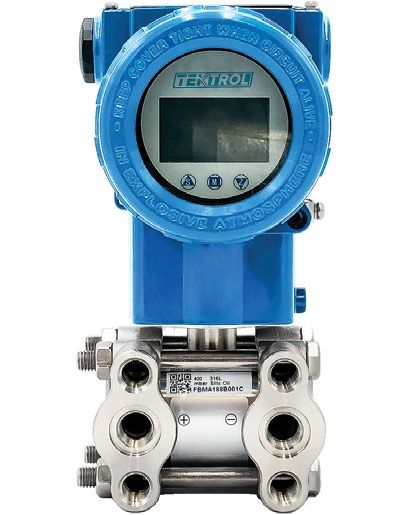
TEK-BAR 3800E
Utilities/Non-Explosion Proof Multivariable Transmitter
PRESSURE
www.tek-trol.com
Flow | Level | Temperature | Pressure | Valves | Analyzers | Accessories | TekValSysIntroduction
Tek-Bar 3800E is an advanced Utilities/Non-Explosion Proof Multivariable Transmitter designed for
simultaneous measurement of multiple independent process variables. The device is suitable in a wide range
of liquid, gas, and steam applications for measuring static pressure, differential pressure, temperature, and
mass flow. The Tek-Bar 3800E is highly stable with accurate sensors offering unprecedented performance in
terms of accuracy, repeatability, and reliability.
Tek-Bar 3800E displays output on its local indicator as well as supports HART communication protocol
for remote set-up and control. Delivering simultaneous real-time measurements, this device is capable of
instantaneous and cumulative mass flow calculations and data acquisition. Additional features include easy
set-up, quick response-time, self-diagnostics and alarm indicators.
The Tek-Bar 3800E offers precise and reliable measurements in harsh environments due to its fully welded
construction. It has the capability to measure multiple variables with one transmitter, thus minimizing pipe
penetrations, wiring costs and installation time.
Measuring Principle and Operation
Tek-Bar 3800E Utilities/Non-Explosion Proof Multivariable Transmitter consists of two functional units: - Main
Unit and Auxiliary Unit.
Filling liquid
DP sensor
AP sensor
Temp. sensor
Over load diaphragm
Isolating diaphragm
Process connection
Sensor body
The main unit is composed of sensors and process connections. The completely sealed dual-chamber sensor
module comprises of an overload diaphragm, absolute pressure sensor, differential pressure sensor and
temperature sensor.
The differential pressure sensor senses the pressure across a primary flow element such as an orifice plate,
flow nozzle, venturi etc. The absolute pressure sensor acts as a reference value to compensate for static
pressure, hence is only exposed to the higher-pressure side. The temperature is measured by a standard 100
Ω RTD. The temperature sensor also acts as a temperature compensated reference value to compensate for
the temperature drift. The auxiliary unit includes a terminal block, power supply and HART communicator.
The advanced software of the transmitter allows further complex calculations such as mass flow, density,
and level measurement of the process fluid. These calculations are compensated against drifts in discharge
coefficient, viscosity, thermal expansion factor, and gas expansion factor. Located at the top of the metal body,
away from the process fluid, the sensor module is mechanically and thermally isolated.
2 tektrol@tek-trol.com | www.tek-trol.comBenefits
• Suitable for wide range of media such as steam, liquid, general gas
• Fully sealed sensor encapsulation for harsh environment
• Protected against severe pressure and temperature spikes
• Optional LCD display with convenient push buttons for configuration
• 4-20 mA or RS485 protocol enabled
• Convenient 360° rotatable display module
• High accuracy up to ±0.075% FS
Applications
• Steam
• Medical or pharmaceutical
• Engine control, pneumatic hydraulic machines
• Chemical and petrochemical
• Air conditioning, refrigeration systems
• Water and wastewater
• Power Plants
Dimensional Drawing
Horizontal Impulse Piping Type (Side face) Horizontal Impulse Piping Type (Front side)
8”
200mm (LCD display) 2 1/8"
(53mm)
51/2”
4 3/4"
135.75mm (LCD display)
(122mm)
LCD Display(option)
Ground Terminal
Ø 83
Relief Valve (option)
(195.75mm)
(182mm)
7 3/4 "
7 1/4 "
2 1/2" 2 1/2"
(62.75mm) Relief Valve (option) (62.75mm)
2 1/8" 5 1/2"
(53mm) Mounting bracket (for pipe & well) (139.75mm)
tektrol@tek-trol.com | www.tek-trol.com 3Horizontal Impulse Wall Mounting Type Vertical Impulse Piping Type
7"
(175mm)
2" pipe (Ø60.5)
Oval-Shaped Flange (option)
2 1/2"
(62.75mm)
Specification
Physical Specification
Wetted Parts Materials
Sensor Body 316 SS
Isolating Diaphragm 316 SS or Hastelloy C
Cover Flange 316 SS
Nuts and Bolts 304 SS
Process Connector 316 SS
Fill Fluid Silicone Oil or Fluorinated Oil
Fluoroeleastomer (FKM) or Polytetrafluoroethylene
Process Connector Gasket
(PTFE)
Amplifier Housing Aluminum with epoxy resin coat
Housing Gasket NBR
Name Plate and Tag 304 SS
Protection IP67
Weight 7.27 lb (3.3 Kg)
Connections
Process Connections ¼" Female NPT, Relief valve
Electrical Connections ½" NPT conduit connections
4 tektrol@tek-trol.com | www.tek-trol.comElectrical Specification
Power Supply (Vs) 24 VDC
Load Resistance (RL) RL≤(Us-12 V) / Imax kΩ
Maximum Current (Imax) 23mA
Output 2-wire 4-20mA, Modbus RS485 or Pulse
Performance Specification
Reference Accuracy ± 0.075% FS
Long Term Stability ±0.1% FS for 3 years
Over Pressure ±0.1% FS for 10 MPa
Measuring Temperature -58 °F to 1202 °F (-50 °C to 650 °C)
Ambient Temperature -40 °F to 185 °F (-40 °C to 85 °C)
-40 °F to 185 °F (-40 °C to 85 °C)
Storage Temperature
-58 °F to 185 °F (-50 °C to 85 °C)
Maximum Working Pressure 0.25 Mpa, 2 Mpa, 10 Mpa, 40 Mpa
Response Time 0.1-1.6 sec.
Functional Specification
Span and Range Limits for DP sensor
Span Min of Span Max of Span Working Pressure
0.25/2/10/40 MPa
B 0" w.c. (0 Pa) 24" w.c. (6 kPa)
(36/290/1450/5800 psi)
2/10/40 MPa
C 0" w.c. (0 kPa) 160" w.c. (40 kPa)
(290/1450/5800 psi)
2/10/40 MPa
D 0" w.c. (0 kPa) 1000" w.c. (250 kPa)
(290/1450/5800 psi)
2/10/40 MPa
E 0 psid (0 kPa) 290 psid (2 Mpa)
(290/1450/5800 psi)
Span of Static Pressure Sensor
Span Working Pressure
1 36 psi (0.25 MPa) 36 psi (0.25 MPa)
2 290 psi (2 Mpa) 290 psi (2 Mpa)
3 1450 psi (10 MPa) 1450 psi (10 MPa)
4 5800 psi (40 MPa) 5800 psi (40 MPa)
tektrol@tek-trol.com | www.tek-trol.com 5Installation
• Ensure that the operating staff handling the pressure instrument is professionally trained
• The transmitter should be direct-mounted to an instrument manifold or secured to a pipe or wall
• Depending on application, install the transmitter vertically / horizontally, directly on the impulse lines or
on the wall using mounting brackets
• Rotate the electronic housing (360° capable) to a comfortable position
• While fitting the connections, ensure that the torque meets maximum pressure rating requirements
• Avoid sediment deposition in impulse piping
• In case of liquid applications, vent all gas from piping legs and avoid trapped air
• Ensure there are no pressure leakage points in the connection
• Maintain equal head pressure on both legs of impulse piping
Liquid Flow
Place taps on the side and mount the transmitter beside or below the taps. Ensure that the drain / vent
valves are oriented upwards.
Flow
Liquid
Gas Flow
Place taps on the top of the line and mount the transmitter above the taps.
Flow
Gas
6 tektrol@tek-trol.com | www.tek-trol.comSteam Flow
Use impulse lines to place the transmitter away from the line. Place taps on the side of the line. Mount the
transmitter beside or below the taps. Fill impulse lines with water at start-up.
Flow
Steam
Model Chart
Example Tek-Bar 3800E B C 3 A B F 1 BF Tek-Bar 3800E-B-C-3-A-B-F-1-BF
Utilities/Non-Explosion Proof
Series Tek-Bar 3800E Multivariable Transmitter
Accuracy B ± 0.075% FS
B 0 to 24" w.c. ( 0 to 6 kPa)
C 0 to 160" w.c. ( 0 to 40 kPa)
Differential Pressure Range
D 0 to 1000" w.c. ( 0 to 250 kPa)
E 0 to 290 psid (0 to 2 MPa)
1 0 to 36 psi ( 0 to 0.25 MPa)
2 0 to 290 psi (0 to 2 MPa)
Static Pressure Range
3 0 to 1450 psi (0 to 10 MPa)
4 0 to 5800 psi (0 to 40 MPa)
A 316 Stainless Steel, Silicone Oil
B 316 Stainless Steel, Fluorinated Oil
Diaphragm and Fill Fluid
C Hastelloy C, Silicone Oil
D Hastelloy C, Fluorinated Oil
Process Connection B ¼" Female NPT, Relief Valve
F Fluoroeleastomer (FKM)
Process Gasket
P PTFE
1 LCD Display
LCD Display
N No LCD Display
BF 304SS Mounting Bracket
O ½" NPT Oval Flange Process
Connection Adaptors
Options
FC Factory Configuration
TAG Custom Nameplate
CC NIST Calibration, 5 Points
tektrol@tek-trol.com | www.tek-trol.com 7Customer Service & Support
DOC # TEK/PO/210701/3800E/r00.3
TEKMATION LLC reserves the right to change the designs and/or materials of its products without notice. The contents of this publication are the property
of TEKMATION and cannot be reproduced by any other party without written permission. All rights reserved. Copyright © 2021TEKMATION LLC
TEKMATION LLC
www.tek-trol.com
Tek-Trol LLC
796 Tek Drive Crystal Lake, IL 60014,
USA
Sales: +1 847-857-6076
Tek-DPro Flow Solutions Tek-Trol Solutions BV Tek-Trol Middle East FZE
PO Box 121 Windsor, Colorado 80550, Florijnstraat 18, 4879 AH Etten-Leur, SAIF Zone, Y1-067, PO BOX No.
USA Netherlands 21125, Sharjah, UAE
Sales: +1 847-857-6076 Sales: +31 76-2031908 Sales: +971-6526-8344
Support: +1 847-857-6076 Email: tektrol@tek-trol.com www.tek-trol.com
Tek-Trol is a fully owned subsidiary of TEKMATION LLC. We offer our customers a comprehensive range of products and solutions for
process, power and oil & gas industries. Tek-Trol provides process measurement and control products for Flow, Level, Temperature
& Pressure measurement, Control valves & Analyzer systems. We are present in 15 locations globally and are known for our
knowledge, innovative solutions, reliable products and global presence.
Flow | Level | Temperature | Pressure | Valves | Analyzers | Accessories | TekValSysYou can also read