Terminator P4 533 Barebone System - User's Guide
←
→
Page content transcription
If your browser does not render page correctly, please read the page content below
®

                   Terminator P4 533
Barebone System

User’s Guide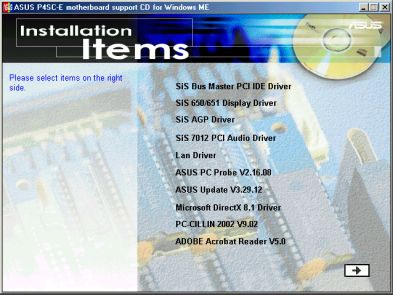
Disclaimer/Copyrights
                Copyright © 2002 ASUSTeK COMPUTER INC. All Rights Reserved.
Checklist

                No part of this manual, including the products and software described in it, may be
                reproduced, transmitted, transcribed, stored in a retrieval system, or translated into any
                language in any form or by any means, except documentation kept by the purchaser for
                backup purposes, without the express written permission of ASUSTeK COMPUTER INC.
                (“ASUS”).
                Product warranty or service will not be extended if: (1) the product is repaired, modified or
                altered, unless such repair, modification of alteration is authorized in writing by ASUS; or (2)
                the serial number of the product is defaced or missing.
                ASUS PROVIDES THIS MANUAL “AS IS” WITHOUT WARRANTY OF ANY KIND, EITHER
                EXPRESS OR IMPLIED, INCLUDING BUT NOT LIMITED TO THE IMPLIED WARRANTIES
                OR CONDITIONS OF MERCHANTABILITY OR FITNESS FOR A PARTICULAR PURPOSE.
                IN NO EVENT SHALL ASUS, ITS DIRECTORS, OFFICERS, EMPLOYEES OR AGENTS BE
                LIABLE FOR ANY INDIRECT, SPECIAL, INCIDENTAL, OR CONSEQUENTIAL DAMAGES
                (INCLUDING DAMAGES FOR LOSS OF PROFITS, LOSS OF BUSINESS, LOSS OF USE
                OR DATA, INTERRUPTION OF BUSINESS AND THE LIKE), EVEN IF ASUS HAS BEEN
                ADVISED OF THE POSSIBILITY OF SUCH DAMAGES ARISING FROM ANY DEFECT OR
                ERROR IN THIS MANUAL OR PRODUCT.
                SPECIFICATIONS AND INFORMATION CONTAINED IN THIS MANUAL ARE FURNISHED
                FOR INFORMATIONAL USE ONLY, AND ARE SUBJECT TO CHANGE AT ANY TIME
                WITHOUT NOTICE, AND SHOULD NOT BE CONSTRUED AS A COMMITMENT BY ASUS.
                ASUS ASSUMES NO RESPONSIBILITY OR LIABILITY FOR ANY ERRORS OR
                INACCURACIES THAT MAY APPEAR IN THIS MANUAL, INCLUDING THE PRODUCTS
                AND SOFTWARE DESCRIBED IN IT.
                Products and corporate names appearing in this manual may or may not be registered
                trademarks or copyrights of their respective companies, and are used only for identification or
                explanation and to the owners’ benefit, without intent to infringe.

                  Product Name:              ASUS Terminator P4 533 Barebone System
                  Manual Revision:           1.00 E1032
                  Release Date:              June 2002

            2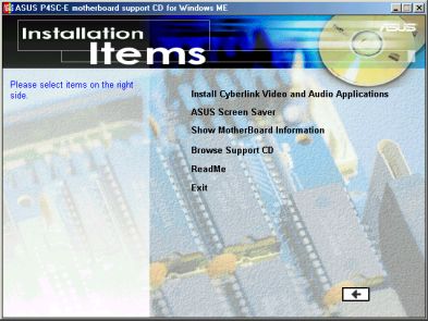
Table of contents
    Disclaimer/Copyrights .................................................................... 2

                                                                                                              Features
    FCC/CDC statements ..................................................................... 5
    Safety information .......................................................................... 6
    About this guide .............................................................................. 7
    ASUS contact information .............................................................. 9
    System package contents ............................................................ 10
Chapter 1: System Introduction ........................................... 11
    1.1      Front Panel Features ......................................................... 12
    1.2      Rear Panel Features .......................................................... 13
    1.3      Internal Features ................................................................ 14
Chapter 2: Basic Installation ................................................ 15
    2.1  Remove the cover ..............................................................             16
    2.2  Detach the drive frame .......................................................              17
    2.3  Install a CPU ......................................................................        19
    2.4  Install the CPU heatsink and fan ........................................                   21
    2.5  Install system memory .......................................................               23
    2.6  Install a hard disk drive ......................................................            24
    2.7  Install a CD-ROM drive ......................................................               26
    2.8  Install a PCI expansion card ..............................................                 28
    2.9  Re-connect cables .............................................................             29
         2.9.1 Front panel ............................................................              29
         2.9.2 UAEX and USB-CF extension modules ................                                    30
    2.10 Replace the cover ..............................................................            31
    2.11 Connect External Devices ..................................................                 33
    2.12 Power Supply Specifications ..............................................                  34
         2.12.1 Input Characteristics .............................................                  34
         2.12.2 Output Characteristics ...........................................                   34
         2.12.3 Over-Voltage Protection (OVP) .............................                          34
Chapter 3: Motherboard Information ................................... 35
    3.1      Introduction ........................................................................   36
    3.2      Motherboard components ..................................................               36
    3.3      Motherboard layout ............................................................         39
    3.4      Central Processing Unit (CPU) ..........................................                40

                                                                                                          3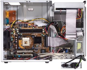
3.5    System memory .................................................................         41
               3.5.1 Memory configurations ..........................................                  41
        3.6    Expansion slots ..................................................................      42
               3.6.1 Configuring an expansion card .............................                       42
               3.6.2 Standard Interrupt Assignments ............................                       42
               3.6.3 IRQ assignments for this motherboard .................                            42
        3.7    Jumpers .............................................................................   43
        3.8    Connectors .........................................................................    45
    Chapter 4: BIOS Information ................................................ 55
        4.1    Managing and updating the BIOS ......................................                   54
               4.1.1 Using the computer system for the first time .........                            54
               4.1.2 Updating BIOS procedures ...................................                      56
        4.2    BIOS Setup program ..........................................................           58
               4.2.1 BIOS menu bar .....................................................               59
               4.2.2 Legend bar ............................................................           59
        4.3    Main Menu .........................................................................     61
               4.3.1 Primary and Secondary Master/Slave ...................                            63
               4.3.2 Keyboard Features ................................................                67
        4.4    Advanced Menu .................................................................         68
               4.4.1 Chip Configuration ................................................               70
               4.4.2 I/O Device Configuration .......................................                  72
               4.4.3 PCI Configuration ..................................................              74
        4.5    Power Menu .......................................................................      77
               4.5.1 Power Up Control ..................................................               79
               4.5.2 Hardware Monitor ..................................................               81
        4.6    Boot Menu ..........................................................................    83
        4.7    Exit Menu ...........................................................................   85
    Chapter 5: Starting up ........................................................... 89
        5.1    Install an operating system ................................................            90
        5.2    Support CD information ......................................................           90
               5.2.1 Running the support CD ........................................                   90
               5.2.2 Installation menus .................................................              91
               5.2.3 Software and drivers description ...........................                      92
        5.3    Software information ..........................................................         94
               5.3.1 ASUS Update ........................................................              94
               5.3.2 ASUS PC Probe ....................................................                96

4
FCC/CDC statements
Federal Communications Commission Statement
This device complies with FCC Rules Part 15. Operation is subject to the
following two conditions:
•     This device may not cause harmful interference, and
•     This device must accept any interference received including
      interference that may cause undesired operation.
This equipment has been tested and found to comply with the limits for a
Class B digital device, pursuant to Part 15 of the FCC Rules. These limits
are designed to provide reasonable protection against harmful interference
in a residential installation. This equipment generates, uses and can
radiate radio frequency energy and, if not installed and used in
accordance with manufacturer’s instructions, may cause harmful
interference to radio communications. However, there is no guarantee that
interference will not occur in a particular installation. If this equipment does
cause harmful interference to radio or television reception, which can be
determined by turning the equipment off and on, the user is encouraged to
try to correct the interference by one or more of the following measures:
•     Reorient or relocate the receiving antenna.
•     Increase the separation between the equipment and receiver.
•     Connect the equipment to an outlet on a circuit different from that to
      which the receiver is connected.
•     Consult the dealer or an experienced radio/TV technician for help.

     WARNING!
     The use of shielded cables for connection of the monitor to the graphics
     card is required to assure compliance with FCC regulations. Changes
     or modifications to this unit not expressly approved by the party
     responsible for compliance could void the user’s authority to operate
     this equipment.

Canadian Department of Communications Statement
This digital apparatus does not exceed the Class B limits for radio noise
emissions from digital apparatus set out in the Radio Interference
Regulations of the Canadian Department of Communications.
This class B digital apparatus complies with Canadian ICES-003.

                                                                                   5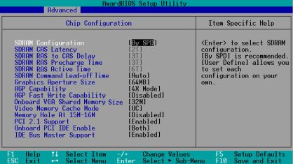
Safety information
    Electrical safety
    •   To prevent electrical shock hazard, disconnect the power cable from
        the electrical outlet before relocating the system.
    •   When adding or removing devices to or from the system, ensure
        that the power cables for the devices are unplugged before the
        signal cables are connected.
    •   Before connecting or removing cables from the motherboard,
        ensure that all power cables are unplugged.
    •   Seek professional assistance before using an adapter or extension
        cord. These devices could interrupt the grounding circuit.
    •   Make sure that your power supply is set to the correct voltage in
        your area. If you are not sure about the voltage of the electrical
        outlet you are using, contact your local power company.
    •   If the power supply is broken, do not try to fix it by yourself. Contact
        a qualified service technician or your retailer.

    Operation safety
    •   Before installing devices into the system, carefully read all the
        documentation that came with the package.
    •   Before using the product, make sure all cables are correctly
        connected and the power cables are not damaged. If you detect any
        damage, contact your dealer immediately.
    •   To avoid short circuits, keep paper clips, screws, and staples away
        from connectors, slots, sockets and circuitry.
    •   Avoid dust, humidity, and temperature extremes. Do not place the
        product in any area where it may become wet.
    •   Place the product on a stable surface.
    •   If you encounter technical problems with the product, contact a
        qualified service technician or your retailer.

6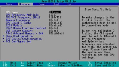
About this guide
Audience
This guide provides general information and installation instructions about
the ASUS Terminator P4 533 Barebone System. This guide is intended for
experienced users and integrators with hardware knowledge of personal
computers.

How this guide is organized
This document contains the following parts:
1.   Chapter 1: System Introduction
     This chapter gives a general description of the ASUS Terminator P4
     533 barebone system. It includes introduction on the front and rear
     panel features, and the internal features.
2.   Chapter 2: Basic Installation
     This chapter tells how to install components into the barebone system
     through illustrated step-by-step instructions.
3.   Chapter 3: Motherboard Information
     This chapter gives information about the P4SC-E motherboard that
     came with the system.This chapter includes the motherboard layout,
     jumper settings, and connector locations. It also includes information
     on the USB/audio board located on the front panel.
4.   Chapter 4: BIOS information
     This chapter tells how to change system settings through the BIOS
     Setup menus. It includes detailed descriptions of the BIOS
     parameters.
5.   Chapter 5: Starting up
     This chapter helps you power up your system and install drivers and
     utilities that came with the support CD.

                                                                              7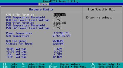
About this guide
Safeguards

                 Conventions used in this guide

                      WARNING!        Information to prevent injury to yourself when
                                      trying to complete a task.
                      CAUTION!        Information to prevent damage to the
                                      components when trying to complete a task.
                      IMPORTANT Information that you MUST follow to complete a
                                task.
                      NOTE            Tips and additional information to aid in
                                      completing a task.

                 Where to find more information
                 Refer to the following sources for additional information and for product
                 and software updates.
                 1.   ASUS Websites
                      The ASUS websites worldwide provide updated information on ASUS
                      hardware and software products. The ASUS websites are listed on
                      page 9.
                 2.   Optional Documentation
                      Your product package may include optional documentation, such as
                      warranty flyers, that may have been added by your dealer. These
                      documents are not part of the standard package.

             8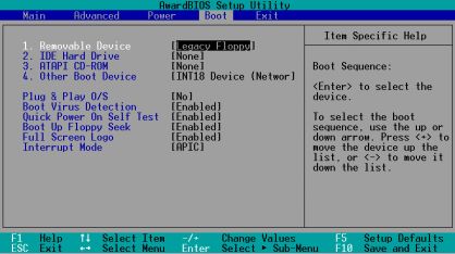
ASUS contact information
ASUSTeK COMPUTER INC. (Asia-Pacific)
Address:                150 Li-Te Road, Peitou, Taipei, Taiwan 112
General Tel:            +886-2-2894-3447
General Fax:            +886-2-2894-3449
General Email:          info@asus.com.tw

Technical Support
MB/Others (Tel):        +886-2-2890-7121 (English)
Notebook (Tel):         +886-2-2890-7122 (English)
Desktop/Server (Tel):   +886-2-2890-7123 (English)
Support Fax:            +886-2-2890-7698
Support Email:          tsd@asus.com.tw
Web Site:               www.asus.com.tw
Newsgroup:              cscnews.asus.com.tw

ASUS COMPUTER INTERNATIONAL (America)
Address:                6737 Mowry Avenue, Mowry Business Center,
                        Building 2, Newark, CA 94560, USA
General Fax:            +1-510-608-4555
General Email:          tmd1@asus.com

Technical Support
Support Fax:            +1-510-608-4555
General Support:        +1-502-995-0883
Web Site:               www.asus.com
Support Email:          tsd@asus.com

ASUS COMPUTER GmbH (Europe)
Address:                Harkortstr. 25, 40880 Ratingen, BRD, Germany
General Fax:            +49-2102-442066
General Email:          sales@asuscom.de (for marketing requests only)

Technical Support
Support Hotline:        MB/Others: +49-2102-9599-0
Notebook (Tel):         +49-2102-9599-10
Support Fax:            +49-2102-9599-11
Support (Email):        www.asuscom.de/de/support (for online support)
Web Site:               www.asuscom.de

                                                                         9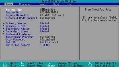
System package contents
     Check your ASUS Terminator P4 533 pacakge for the following items:
     1.   Barebone system
     2.   Motherboard
     3.   Switching power supply
     4.   1.44MB floppy disk drive
     5.   CD-ROM Drive (optional)
     6.   56K PCI modem card (optional)
     7.   Support CD
     8.   User’s guide

          NOTE
          Optional items may not be present in your package.

          If any of the above items is damaged or missing, contact your dealer
          immediately.

          IMPORTANT
          If you are assembling the system by yourself, make sure to prepare all
          the components before starting. It saves you a lot of time not having to
          hunt down components when you need them.

10
Chapter 1
System Introduction
This chapter gives a general description of
the ASUS Terminator P4 533 barebone
system. It includes introduction on the front
and rear panel features, and the internal
features.
ASUS Terminator P4 533 Barebone System 111.1 Front Panel Features
The ASUS Terminator P4 533 barebone system is composed of the ASUS
P4SC motherboard, a power supply, and a floppy disk drive in the ASUS
TriOptix form factor chassis. The chassis front bezel may vary as shown.
NOTE
The CD-ROM drive and modem card are optional items.
Chassis 1 Chassis 2
CD-ROM
Drive
(optional)
Floppy Drive
Power Button
Power LED
HDD LED
CF Card Slot Headphone Jack CF Card Slot Headphone Jack
USB Ports Microphone Jack USB Ports Microphone Jack
Front Panel
I/O Door
Front Panel I/O Door
The lower part of the front panel is a door that covers accessible I/O
features including a Compact Flash card slot, two USB ports (Ports 2&3),
a headphone jack, and a microphone jack.
Open chassis 1 I/O door by pressing the dotted area of the door.
Open chassis 2 I/O door by flipping up the door.
12 Chapter 1: System Introduction1.2 Rear Panel Features
The rear panel of the ASUS Terminator P4 533 barebone system includes
the standard PC99 I/O connectors for external devices, power supply
socket, and optional modem connectors.
The following figure shows the rear panel features.
Game/MIDI Connector
Serial Port (COM1)
PS/2 Mouse Connector
PS/2 Keyboard Connector
VGA Port
Parallel Connector
Line Out Connector
Line In Connector
Microphone Connector
LAN Connector (RJ-45)
USB Connectors (Ports 0&1)
Modem (optional) Power Socket
Voltage Selector
The switching power supply that came with
the system has a voltage selector switch
below the power socket. Use this switch to
select the appropriate voltage according to
the voltage supply in your area.
If the voltage supply in your area is 100-127V,
set the switch to 115V.
If the voltage supply in your area is 200-240V,
set the switch to 230V. 115V/230V
Voltage Selector
CAUTION!
Setting the switch to 115V in a 230V environment will seriously damage
the system!
ASUS Terminator P4 533 Barebone System 131.3 Internal Features
The figure below shows the internal view of the system when you remove
the cover and flip out the drive frame. You will see here the standard
components that come already installed in the system and the places
where you can install the other required components to get the system
running.
Game/MIDI/COM1 Two 5.25” 3.5” HDD
Extension Module Drive Bays Drive Bay 3.5” Floppy Drive
Modem Card Motherboard USB/audio Power Supply
(optional) Board
14 Chapter 1: System IntroductionChapter 2
This chapter tells how to install components
into the barebone system through illustrated
Basic Installation
step-by-step instructions.
ASUS Terminator P4 533 Barebone System 152.1 Remove the cover
The chassis cover is secured by a thumbscrew located on the rear panel.
Follow these steps to remove the
chassis cover.
1. Turn the captive thumbscrew
counter-clockwise to release
the cover. You don’t have to
remove the thumbscrew from
the chassis.
Thumbscrew
2. Place your hands on both
corners of the front panel, just
beside the CD-ROM frame.
Push on the CD-ROM area
with your thumbs until the
cover tilts forward.
TIP
Another way to release the cover is
to place your hands underneath the
front panel edge, then push the
inner chassis with your thumbs
while pulling the panel with your
other fingers.
3. While supporting the front
panel with one hand, place
your other hand on the top
rear edge of the cover and
carefully lift the cover from the
chassis.
16 Chapter 2: Basic Installation2.2 Detach the drive frame
Follow these steps to detach the
drive frame.
1. Place the chassis on a flat
surface and turn it on its side.
2. The power socket and voltage
selector switch are attached to
a metal module secured to Power socket
module screw
the rear panel by a screw.
Remove the screw to release
the power socket module.
Power socket module
IMPORTANT
You must release the power socket module from the rear panel before
detaching the drive frame to avoid breaking the power cable.
ASUS Terminator P4 533 Barebone System 173. Place your thumb on the right
edge of the power socket
module, then slide the module
to the right until it is
completely detached from the
rear panel.
4. Unlatch the drive frame by
pulling it outward.
Drive frame
Swivel edge
NOTE
The drive frame has a swivel (hinge-like) edge that is attached to the
main chassis. It is not necessary to completely detach the drive frame
from the chassis when installing components.
5. Carefully lay the drive frame
alongside the main chassis
frame.
18 Chapter 2: Basic Installation2.3 Install a CPU
The P4SC-E motherboard comes with a surface mount 478-pin Zero
Insertion Force (ZIF) socket. This socket is specifically designed for the
Intel® Pentium® 4 478/Northwood Processor.
Follow these steps to install a CPU.
1. Locate the 478-pin CPU
socket on the motherboard.
478-pin CPU socket
2. Unlock the socket by pressing
the lever sideways then lifting
it up to a 90°-100° angle.
Socket lever 90 - 100
IMPORTANT
Make sure that the socket lever is lifted up to 90°-100° angle, otherwise
the CPU does not fit in completely.
ASUS Terminator P4 533 Barebone System 193. Position the CPU above the
socket such that its marked
corner (gold mark) matches
the base of the socket lever.
4. Carefully insert the CPU into
Gold mark
the socket until it fits in place.
CAUTION
The CPU fits only in one correct orientation. DO NOT force the CPU
into the socket to prevent bending the pins and damaging the CPU!
5. When the CPU is in place,
press it firmly on the socket
while you push down the
socket lever to secure the
CPU. The lever clicks on the
side tab to indicate that it is
locked.
20 Chapter 2: Basic Installation2.4 Install the CPU heatsink and fan
The Intel® Pentium® 4 478/Northwood Processor requires a specially
designed heatsink and fan assembly to ensure optimum thermal condition
and performance.
When you buy a boxed Intel Pentium 4 478/Northwood Processor, the
package usually includes the heatsink and fan assembly.
IMPORTANT
Make sure that you use only Intel certified CPU heatsink and fan.
Follow these steps to install the
CPU heatsink and fan.
1. Position the fan heatsink
assembly on top of the
installed CPU such that the
fan cable is nearest the CPU
fan connector on the
motherboard (marked
CPU_FAN1).
2. Align one retention bracket
with the rail on the side of the
heatsink. Orient the bracket
such that the locking lever is
on the side of the PCI slots.
3. Snap the hook of the metal
retention bracket into the hole
of the retention module.
4. Follow steps 2 and 3 to attach
the second retention bracket. Locking lever
Retention bracket Hole on the retention module
ASUS Terminator P4 533 Barebone System 215. Carefully press down the
locking lever on the other side
of the bracket and hook its end
into the hole of the retention
module to secure the fan
heatsink assembly in place.
6. Follow step 5 to lock the
second bracket.
Locking lever
7. Connect the CPU fan cable
from the assembly to the fan
connector labeled CPU_FAN1.
CPU fan connector
(CPU_FAN1)
NOTE
Your boxed Intel Pentium 4 478/Northwood Processor package may
come with installation instructions for the CPU and fan heatsink
assembly. If the instructions in this section do not match the
documentation for the CPU or fan heatsink, follow the latter.
22 Chapter 2: Basic Installation2.5 Install system memory
The motherboard comes with two Double Data Rate (DDR) Dual Inline
Memory Module (DIMM) sockets. These sockets support up to 2GB
system memory using unbuffered ECC or non-ECC PC2700/1600/2100
DIMMs.
Follow these steps to install a DDR
DIMM.
1. Locate the two DIMM sockets
on the motherboard.
DDR DIMM sockets
2. Unlock a socket by pressing
the retaining clips outward.
3. Align a DIMM on the socket
such that the notch on the
DIMM matches the break on
the socket. DIMM notch
Socket break
4. Firmly insert the DIMM into the
socket until the retaining clips
snap back in place and the
DIMM is properly seated.
CAUTION
A DDR DIMM is keyed with a notch so that it fits in only one direction.
DO NOT force a DIMM into a socket to avoid damaging the DIMM.
ASUS Terminator P4 533 Barebone System 232.6 Install a hard disk drive
The chassis has one 3.5-inch hard disk drive (HDD) bay right under the
5.25-inch bay. The following figures show the internal and external views
of the HDD bay location.
Internal View External View
5.25-inch Drive Bay
3.5-inch HDD Drive Bay
Follow these steps to install an IDE
HDD.
1. Place the chassis upright.
2. With the HDD label side up,
carefully insert the drive into
the 3.5-inch bay.
HDD label side
3. Push the drive into the bay
until its screw holes align with
the holes on the bay marked
HDD.
4. Secure the drive with two
screws on each side of the
bay.
HDD screws
24 Chapter 2: Basic Installation5. Connect a power cable from
the power supply to the power
connector at the back of the
HDD. Use the cable with the
white connector labeled P3.
6. Connect one end of the IDE
hard disk ribbon cable to the
IDE interface at the back of
the HDD, matching the red
stripe on the cable with Pin 1
Red Stripe to Pin 1
on the IDE interface.
IDE Ribbon Cable Power Cable (P3)
7. Connect the other end of the
IDE ribbon cable to the
primary IDE connector (blue
connector labeled PRI_IDE1)
on the motherboard.
Primary IDE connector
(PRI_IDE1)
ASUS Terminator P4 533 Barebone System 252.7 Install a CD-ROM drive
A CD-ROM drive is an optional item in this barebone system. Refer to the
instructions in this section if you acquired a model without a CD-ROM.
Follow these steps to install a
CD-ROM drive.
1. Place the chassis upright.
2. Insert the CD-ROM drive into
the upper 5.25-inch drive bay.
5.25-inch drive bay
3. Carefully push the CD-ROM
drive into the bay until its
screw holes align with the
holes (marked 1) on the bay
as shown.
4. Secure the CD-ROM with two
screws on each side of the
bay.
CD-ROM screws
26 Chapter 2: Basic Installation5. Connect a power cable from
the power supply to the power
connector at the back of the
CD-ROM. Use the cable with
the white connector labeled
P1.
6. Connect one end of the IDE
ribbon cable to the IDE
interface at the back of the
CD-ROM, matching the red
stripe on the cable with Pin 1 CD-ROM Audio Cable
on the IDE interface.
IDE Ribbon Cable
7. Connect one end of the Red Stripe to Pin 1
CD-ROM audio cable to the
Power Cable (P1)
4-pin connector at the back of
the CD-ROM.
8. Connect the other end of the
IDE ribbon cable to the
secondary IDE connector
(black connector labeled
PRI_IDE2) on the
motherboard.
Secondary IDE connector
(PRI_IDE2)
9. Connect the other end of the
audio cable to the black 4-pin
connector labeled CD on the
motherboard.
CD-ROM Connector
(CD1)
ASUS Terminator P4 533 Barebone System 272.8 Install a PCI expansion card
The motherboard has two 32-bit PCI slots. If you wish to install a PCI card,
follow the instructions in this section.
The figure on the right shows a
sample PCI network card that you
can install on the PCI slot.
Follow these steps to install a PCI
expansion card.
1. Place the chassis on its side.
2. Remove the metal bracket
cover opposite the PCI slot
that you wish to use.
3. Align the PCI card golden
fingers to the PCI slot and its
metal bracket to the slot
opening on the chassis. Slot Opening PCI Slot 1 (PCI1)
4. Press the card firmly until it is PCI Slot 2 (PCI2)
properly seated on the slot.
5. Secure the card to the chassis
with a bracket screw.
NOTE
If your system came with the optional modem card, one PCI slot is
already occupied.
28 Chapter 2: Basic Installation2.9 Re-connect cables
You may have disconnected some cables when you were installing
components. You must re-connect these cables before you replace the
chassis cover.
2.9.1 LED cables
Power Switch
Power LED
HDD LED
PANEL1 Connector
Speaker
Power LED Connector
Speaker
Ground
Ground
+5VSB
PLED
+5V
MLED
Ground
+5 V
ExtSMI#
Ground
Ground
PWR
Reset
Reset SW
Message LED
ATX Power
SMI Lead Switch*
PANEL1 * Requires an ATX power supply.
IDE_LED1
• Connect the power switch and power LED cables to their respective
leads in the PANEL1 connector on the motherboard.
• Connect the HDD LED cable to the 2-pin lead marked IDE_LED1.
ASUS Terminator P4 533 Barebone System 292.9.2 UAEX and USB-CF extension modules
UAEX
B: Port1
T: Port0
USB
MIC
LOUT
USB2P
®
MIC2
LO2
Connect to MIC_LOUT1 connector Connect to USB_34 connector
on the motherboard
USB_CF
on the motherboard
LED3 LED2
CON1
J1
®
Connect to USB_56 connector
on the motherboard
Connector locations on the motherboard
USB_34 USB_56
MIC_LOUT1 connector
(for Microphone/Line Out Cable)
30 Chapter 2: Basic Installation2.10 Replace the cover
After you have installed all the internal components and you have
connected all the necessary cables, you are now ready to put the system
back together.
Follow these steps to re-assemble
the system.
1. With the chassis lying on its
side, hook the swivel edge of
the drive frame to the main
chassis.
2. Sway the drive frame inward
until it fits completely. The
protruding tabs on both ends
of the drive frame should snap
perfectly to the chassis edge.
Protruding Tab
3. Turn the chassis upright.
4. Place the cover over the
chassis leaving about two
inches from the rear panel.
ASUS Terminator P4 533 Barebone System 315. Fit the rail tabs on the sides
and bottom of the cover to the
edges of the chassis.
Rail Tabs
6. Push the cover towards the
rear until it fits. The locking tab
snaps into the hole on the
chassis indicating that the
cover is in place.
Locking Tab
Locking Tab Hole
IMPORTANT
Firmly push the cover to ensure that it is fully engaged to the chassis.
7. Lock the cover with the captive
thumbscrew on the rear panel.
32 Chapter 2: Basic Installation2.11 Connect External Devices
The figure below shows the specific connectors and devices that you can
connect to the rear panel ports.
Serial Game/MIDI
PS/2 KB
VGA PS/2 Mouse
Parallel
Line Out
Line In AC
Mic USB
RJ-45
ASUS Terminator P4 533 Barebone System 332.12 Power Supply Specifications
2.12.1 Input Characteristics
Input Voltage Range Min Nom Max
Range 1 90V 115V 135V
Range 2 180V 230V 265V
Input Frequency Range 47 Hz to 63 Hz
Maximum Input ac Current 4A max. at 115Vac
2A max. at 230Vac, maximum load
Inrush Current 90A max. at 115Vac,
full load cold start at 25°C
Efficiency 70% min. at nominal input,
maximum load
2.12.2 Output Characteristics
Output Load Range Regulation Ripple
Voltage Min Max Min Max Max
+5V 0.5A 4.0A -5% +5% 50mVp-p
+12V 0.45A 9.5A -5% +5% 120mVp-p
-12V 0A 0.2A -10% +10% 120mVp-p
+5VSB 0.05A 1.5A -5% +5% 50mVp-p
+3V3 1A 8.0A -5% +5% 50mVp-p
2.12.3 Over-Voltage Protection (OVP)
Output Voltage Maximum Voltage
+5V 6.5V
+12V 15.6V
+3.3V 4.3V
NOTE
The power supply will shut down and latch off for shorting +5V, +12V,
-12V, or +3.3V. By shorting +5VSB, the power supply can latch down or
automatically recover when the fault condition is removed
34 Chapter 2: Basic InstallationChapter 3
This chapter gives information about the
ASUS P4SC-E motherboard that came with
Motherboard Info
the system.This chapter includes the
motherboard layout, jumper settings, and
connector locations. It also includes
information on the USB/audio board located
on the front panel.
IMPORTANT
The ASUS Terminator P4 533 barebone
system is designed to support a motherboard
that measures 23 cm (9.06 in) x 22.4 cm (8.82
in). It is not recommended to install any
motherboard of other sizes. If you need to
replace the original motherboard that came
with the system, make sure that it fits into the
chassis and that the I/O connectors
correspond to the openings on the rear panel.
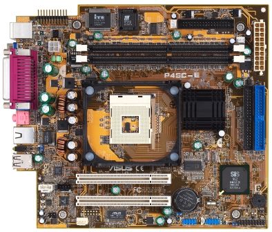
ASUS Terminator P4 533 Barebone System 353.1 Introduction
The ASUS P4SC-E motherboard comes already installed in the ASUS
Terminator P4 533 barebone system. For future upgrades or system
reconfiguration, this chapter provides technical information about the
motherboard.
3.2 Motherboard components
1 2 3 4 5 6 7
8
9
12 11 10
13 14
22 21 20 19 18 17 16 15
36 Chapter 3: Motherboard information1 ATX 12V connector. This power connector connects the 4-pin 12V
plug from the ATX 12V power supply.
2 Super I/O chipset. This Low Pin Count (LPC) interface provides
the commonly used Super I/O functionality. The chipset supports a
high-performance floppy disk controller for a 360K/720K/1.44M/
2.88M floppy disk drive, a multi-mode parallel port, two standard
compatible UARTs, a Standard Infrared (SIR), one MPU-401 UART
mode compatible MIDI/game port, and a Flash ROM interface.
3 Flash ROM. This 2Mb firmware contains the programmable BIOS
program.
4 CPU socket. A 478-pin surface mount, Zero Insertion Force (ZIF)
socket for the Intel® Pentium® 4 478/Northwood Processor with
533/400 MHz system bus that allows 4.3GB/s and 3.2GB/s data
transfer rates, respectively.
5 DDR DIMM sockets. These two 184-pin DIMM sockets support up
to 2GB using unbuffered ECC or non-ECC PC2700/2100/1600
DDR DIMMs.
6 Floppy disk connector. This connector connects the provided
ribbon cable for the floppy disk drive. One side of the connector is
slotted to prevent incorrect insertion of the floppy disk cable.
7 ATX power connector. This 20-pin connector connects to an ATX
12V power supply. The power supply must have at least 1A on the
+5V standby lead (+5VSB).
8 North bridge controller. This SiS651 controller integrates a high
performance host interface for the Intel® Pentium® 4 processor, a
memory controller, an AGP interface, and SiS MuTIOL technology.
9 IDE connectors. These dual-channel bus master IDE connectors
support up to four Ultra DMA133/100/66, PIO Modes 3 & 4 IDE
devices. Both the primary (blue) and secondary (black) connectors
are slotted to prevent incorrect insertion of the IDE ribbon cable.
10 South bridge controller. Referred to as the SiS962L MuTIOL
Media I/O, this controller integrates the audio controller with AC’97
Interface, Ethernet MAC, Dual Universal Serial Bus Host
controllers, IDE Master/Slave controllers, and the MuTIOL Connect
to PCI Bridge.
ASUS Terminator P4 533 Barebone System 3711 PCI slots. These two 32-bit PCI 2.2 expansion slots support bus
master PCI cards like SCSI or LAN cards with 133MB/s maximum
throughput.
12 Audio/Modem CODEC. This audio CODEC is AC ’97 compliant.
13 PS/2 mouse port. This green 6-pin connector is for a PS/2 mouse.
14 Parallel port. This 25-pin port connects a parallel printer, a
scanner, or other devices.
15 USB ports. These two 4-pin Universal Serial Bus (USB) ports are
available for connecting USB devices such as a mouse and PDA.
16 LAN activity LEDs. These LEDs indicate an active network
connection.
17 RJ-45 port. This port allows connection to a Local Area Network
(LAN) through a network hub.
18 Microphone jack. This Mic (pink) jack connects a microphone.
19 Line In jack. This Line In (light blue) jack connects a tape player or
other audio sources.
20 Line Out jack. This Line Out (lime) jack connects a headphone or
a speaker.
21 Video port. This port connects a VGA monitor.
22 PS/2 keyboard port. This purple 6-pin connector is for a PS/2
keyboard.
38 Chapter 3: Motherboard information3.3 Motherboard layout
23cm (9.06in)
Super Flash FLOPPY1
I/O BIOS
ATX Power Connector
PS/2 IOC_MB CHA_FAN1
T:Mouse
B:Keyboard CPU_FAN1
VGA1
DDR DIMM2 (64/72-bit, 184-pin module)
ATX12V1
DDR DIMM1 (64/72-bit, 184-pin module)
PARALLEL PORT
P4SC-E
Line
Out
SiS651
Socket 478
3C
22.4cm (8.82in)
Line
In
Integration
Mic
In Single
Chip
SEC_IDE1
RJ-45
LANLED
USB_PWR12
PRI_IDE1
USB_12
T:Port0
B:Port1 ®
SiS
AUX1 CD1
PCI Slot 1 962L
Chipset
CR2032 3V
Audio
Codec PCI Slot 2 Lithium Cell
CMOS Power BUZZER1
CLRTC1
IDE_LED1
USB_PWR34 USB_56
PANEL1
MIC_LOUT1 MODEM1 USB_34
USB_PWR56
ASUS Terminator P4 533 Barebone System 393.4 Central Processing Unit (CPU)
The motherboard comes with a surface mount 478-pin Zero Insertion
Force (ZIF) socket. This socket is specifically designed for the Intel®
Pentium® 4 478/Northwood Processor.
The Intel Pentium 4 Processor in the 478-pin package uses the Flip-Chip
Pin Grid Array 2 (FC-PGA2) package technology, and includes the Intel®
NetBurst™ micro-architecture. The Intel NetBurst micro-architecture
features the hyper-pipelined technology, rapid execution engine,
533/400MHz system bus, and execution trace cache. Together, these
attributes improve system performance by allowing higher processor
frequencies, faster execution of integer instructions, and a data transfer
rate of 4.3GB/s and 3.2GB/s.
P4SC-E
Gold Arrow
®
P4SC-E Socket 478
NOTE
Refer to sections “2.3 Install a CPU” and “2.4 Install the CPU heatsink
and fan” for instructions on installing the Intel Pentium 4 CPU and the
heatsink/fan assembly.
40 Chapter 3: Motherboard information3.5 System memory
The motherboard has two Double Data Rate (DDR) DIMM sockets that
supports up to 2GB unbuffered non-ECC PC2700/2100/1600 DDR
DIMMs.
A DDR DIMM has the same physical dimensions as an SDR DIMM, but it
has a 184-pin footprint compared to the 168-pin of the SDR DIMM. Also, a
DDR DIMM is single notched while an SDR DIMM is double notched.
Therefore, a DDR DIMM is not backward compatible with SDR, and should
be installed only in a socket specially designed for DDR DIMMs.
P4SC-E
104 Pins 80 Pins
®
P4SC-E 184-Pin DDR DIMM Sockets
3.5.1 Memory configurations
You may install any DDR DIMMs with 64MB, 128MB, 256MB, 512MB, and
1GB densities into the three DIMM sockets.
Use the following combinations to install DDR DIMMs.
DIMM Location 184-pin DDR DIMM Total Memory
Socket 1 (Rows 0&1) 64MB, 128MB, 256MB, 512MB, 1GB x1 =
Socket 2 (Rows 2&3) 64MB, 128MB, 256MB, 512MB, 1GB x1 =
Total system memory (Max. 2GB) =
NOTE
Refer to section “2.5 Install system memory” for instructions on
installing DDR DIMMs.
ASUS Terminator P4 533 Barebone System 413.6 Expansion slots
In the future, you may need to install expansion cards. The motherboard
has two PCI slots.
3.6.1 Configuring an expansion card
After physically installing the expansion card, configure the card by
adjusting the software settings.
1. Turn on the system and change the necessary BIOS settings, if any.
See Chapter 4 for information on BIOS setup.
2. Assign an IRQ to the card. Refer to the tables below.
3. Install the software drivers for the expansion card.
3.6.2 Standard Interrupt Assignments
IRQ Priority Standard Function
0 1 System Timer
1 2 Keyboard Controller
2 N/A Programmable Interrupt
3* 11 Communications Port (COM2)
4* 12 Communications Port (COM1)
5* 13 Sound Card (sometimes LPT2)
6 14 Floppy Disk Controller
7* 15 Printer Port (LPT1)
8 3 System CMOS/Real Time Clock
9* 4 ACPI Mode when used
10* 5 IRQ Holder for PCI Steering
11* 6 IRQ Holder for PCI Steering
12* 7 PS/2 Compatible Mouse Port
13 8 Numeric Data Processor
14* 9 Primary IDE Channel
15* 10 Secondary IDE Channel
*These IRQs are usually available for ISA or PCI devices.
3.6.3 IRQ assignments for this motherboard
A B C D E F G H
PCI slot 1 — used — — — — — —
PCI slot 2 — — used — — — — —
Onboard Audio — — — — — used — —
Onboard LAN — — — — — — used —
42 Chapter 3: Motherboard information3.7 Jumpers
This section describes and illustrates the jumpers on the motherboard.
1. USB device wake-up (3-pin USB_PWR12, USB_PWR34,
USB_PWR56)
Set these jumpers to +5V to wake up the computer from S1 sleep
mode (CPU stopped, DRAM refreshed, system running in low power
mode) using the connected USB devices. Set to +5VSB to wake up
from S3 sleep mode (no power to CPU, DRAM in slow refresh, power
supply in reduced power mode).
The USB_PWR12 jumper is for the rear USB ports. The
USB_PWR34 and USB_PWR56 jumpers are for the internal USB
headers that connect to the front USB ports and USB-CF slot.
NOTES
This feature requires a power supply that can provide at least 1A on the
+5VSB lead when these jumpers are set to +5VSB. Otherwise, the
system does not power up.
The total current consumed must NOT exceed the power supply
capability (+5VSB) whether under normal condition or in sleep mode.
USB_PWR12
1 2
2 3
P4SC-E
+5V +5VSB
(Default)
USB_PWR34
®
USB_PWR56
1 2 2 3
+5V +5VSB
P4SC-E USB Device Wake Up (Default)
ASUS Terminator P4 533 Barebone System 432. Clear RTC RAM (CLRTC1)
These solder points allow you to clear the Real Time Clock (RTC)
RAM in CMOS. You can clear the CMOS memory of date, time, and
system setup parameters by erasing the CMOS RTC RAM data. The
RAM data in CMOS, that include system setup information such as
system passwords, is powered by the onboard button cell battery.
To erase the RTC RAM:
1. Turn OFF the computer and unplug the power cord.
2. Remove the battery.
3. Short the solder points.
4. Re-install the battery.
5. Plug the power cord and turn ON the computer.
6. Hold down the key during the boot process and enter
BIOS setup to re-enter data.
P4SC-E
CR2032 3V
Lithium Cell
CMOS Power
®
CLRTC1
Short solder points
to Clear CMOS
P4SC-E Clear RTC RAM
44 Chapter 3: Motherboard information3.8 Connectors
This section describes and illustrates the connectors on the motherboard.
1. IDE connectors (40-1 pin PRI_IDE1, SEC_IDE1)
This connector supports the provided UltraDMA/133/100/66 IDE hard
disk ribbon cable. Connect the cable’s blue connector to the primary
(recommended) or secondary IDE connector, then connect the gray
connector to the UltraDMA/133/100/66 slave device (hard disk drive)
and the black connector to the UltraDMA/133/100/66 master device.
It is recommended that you connect non-UltraDMA/133/100/66
devices to the secondary IDE connector. If you install two hard disks,
you must configure the second drive as a slave device by setting its
jumper accordingly. Refer to the hard disk documentation for the
jumper settings. BIOS supports specific device bootup. If you have
more than two UltraDMA/133/100/66 devices, purchase another
UltraDMA/133/100/66 cable. You may configure two hard disks to be
both master devices with two ribbon cables – one for the primary IDE
connector and another for the secondary IDE connector.
NOTES
Pin 20 on each IDE connector is removed to match the covered hole on
the UltraDMA cable connector. This prevents incorrect orientation when
you connect the cables.
For UltraDMA/133/100/66 IDE devices, use an 80-conductor IDE cable.
P4SC-E
NOTE: Orient the red markings
(usually zigzag) on the IDE
ribbon cable to PIN 1.
SEC_IDE1
PRI_IDE1
®
PIN 1
P4SC-E IDE Connectors
ASUS Terminator P4 533 Barebone System 452. Floppy disk drive connector (34-1 pin FLOPPY1)
This connector supports the provided floppy drive ribbon cable. After
connecting one end to the motherboard, connect the other end to the
floppy drive. (Pin 5 is removed to prevent incorrect insertion when
using ribbon cables with pin 5 plug).
FLOPPY1
P4SC-E
PIN 1
NOTE: Orient the red markings on
®
the floppy ribbon cable to PIN 1.
P4SC-E Floppy Disk Drive Connector
3. Hard disk activity LED (2-pin IDE_LED1)
This connector supplies power to the hard disk activity LED. The read
or write activities of any device connected to the primary or
secondary IDE connector cause this LED to light up.
P4SC-E
TIP: If the case-mounted LED does not
light, try reversing the 2-pin plug.
®
IDE_LED1
P4SC-E IDE Activity LED
46 Chapter 3: Motherboard information4. ATX power connectors (20-pin ATXPWR, 4-pin ATX +12V)
These connectors connect to an ATX 12V power supply. The plugs
from the power supply are designed to fit these connectors in only one
orientation. Find the proper orientation and push down firmly until the
connectors completely fit.
In addition to the 20-pin ATXPWR connector, this motherboard
requires that you connect the 4-pin ATX +12V power plug to provide
sufficient power to the CPU.
ATXPWR1 +12.0Volts +5.0 Volts
+5V Standby +5.0 Volts
Power Good -5.0 Volts
Ground Ground
+5.0 Volts Ground
Ground Ground
+5.0 Volts Power Supply On
P4SC-E
Ground Ground
+3.3 Volts -12.0Volts
+3.3 Volts +3.3Volts
®
ATX12V1 COM +12V DC
P4SC-E ATX Power Connector COM +12V DC
IMPORTANT
If you will need to replace the power supply in the future, make sure
that your new ATX 12V power supply can provide 8A on the +12V lead
and at least 1A on the +5-volt standby lead (+5VSB). The minimum
recommended wattage is 230W, or 300W for a fully configured system.
The system may become unstable and may experience difficulty
powering up if the power supply is inadequate.
ASUS Terminator P4 533 Barebone System 475. CPU, Chassis, and Power Fan Connectors
(3-pin CPU_FAN1, CHA_FAN1)
The three fan connectors support cooling fans of 350mA (4.2 Watts)
or a total of 1A (12W) at +12V. Orient the fans so that the heat sink
fins allow air flow to go across the onboard heat sinks instead of the
expansion slots. The fan wiring and plug may vary depending on the
fan manufacturer. Connect the fan cable to the connector matching
the black wire to the ground pin.
Rotation
+12V
GND
CPU_FAN1
P4SC-E
CHA_FAN1
Rotation
+12V
®
GND
P4SC-E 12-Volt Cooling Fan Power
IMPORTANT
Do not forget to connect the fan cables to the fan connectors. Lack of
sufficient air flow within the system may damage the motherboard
components. These are not jumpers! DO NOT place jumper caps on
the fan connectors!
48 Chapter 3: Motherboard information6. USB headers (10-1 pin USB2)
The USB_34 header is connected to the USB2P connector in the
UAEX extension module on the front panel for two additional USB 2.0
ports.
The USB_56 header (pins 6 to 10) is connected to the J1 connector
on the USB_CF extenstion module on the front panel to support the
Compact Flash card reader.
P4SC-E
USB Power
USB Power
USBP2+
USBP2+
USBP2–
USBP2–
GND
GND
NC
NC
®
1 5 1 5
USB_34 USB_56
6 10 6 10
USB Power
USBP3–
USBP3+
GND
USB Power
USBP3–
USBP3+
GND
P4SC-E USB Ports
7. Internal audio connectors (4-pin AUX1, CD1, MODEM1)
These connectors allow you to receive stereo audio input from sound
sources such as a CD-ROM, TV tuner, or MPEG card. The MODEM
connector allows the onboard audio to interface with a voice modem
card with a similar connector. It also allows the sharing of mono_in
(such as a phone) and a mono_out (such as a speaker) between the
audio and a voice modem card.
Right Audio Channel
Right Audio Channel
Left Audio Channel
Left Audio Channel
P4SC-E
Ground
Ground
®
AUX1 (White) CD1 (Black)
Modem-In (to Modem)
Ground
Modem-Out (from Modem)
P4SC-E Internal Audio Connectors MODEM1
ASUS Terminator P4 533 Barebone System 498. Front panel audio connectors (5-1 pin MIC_LOUT1)
This connector connects to a front panel audio module using an audio
cable. If your chassis has this audio module, you may conveniently
connect a microphone and a speaker/headphone on the front panel.
MIC_LOUT1
P4SC-E
Head set Left channel
Head set Right channel GND
®
1
1
MIC PWR MIC Signal
P4SC-E Microphone Header
9. IO extension module connector (22-pin IOC_MB)
This connector is for the CGAEX extension module.
P4SC-E
COM1 GAME
®
CGAEX
®
IOC_DC
P4SC-E IOC_MB Connector
50 Chapter 3: Motherboard information10. System panel connector (20-pin PANEL1)
This connector accommodates several system front panel functions.
Speaker
Power LED Connector
Speaker
Ground
Ground
+5VSB
PLED
P4SC-E
+5V
MLED
Ground
+5 V
ExtSMI#
Ground
Ground
PWR
Reset
®
Reset SW
Message LED
ATX Power
SMI Lead Switch*
* Requires an ATX power supply.
P4SC-E System Panel Connectors
• System Power LED Lead (3-1 pin PLED)
This 3-1 pin connector connects to the system power LED. The LED
lights up when you turn on the system power, and blinks when the
system is in sleep mode.
• System Warning Speaker Lead (4-pin SPEAKER)
This 4-pin connector connects to the case-mounted speaker and
allows you to hear system beeps and warnings.
• System Message LED Lead (2-pin MLED)
This 2-pin connector is for the system message LED that indicates
receipt of messages from a fax/modem. The normal status for this
LED is OFF, when there is no incoming data signal. The LED blinks
when data is received. The system message LED feature requires
an ACPI OS and driver support.
• System Management Interrupt Lead (2-pin SMI)
This 2-pin connector allows you to manually place the system into a
suspend mode, or “green” mode, where system activity is instantly
decreased to save power and to expand the life of certain system
components. Attach the case-mounted suspend switch to this 2-pin
connector.
ASUS Terminator P4 533 Barebone System 51• ATX Power Switch / Soft-Off Switch Lead (2-pin PWR)
This connector connects a switch that controls the system power.
Pressing the power switch turns the system between ON and SLEEP,
or ON and SOFT OFF, depending on the BIOS or OS settings.
Pressing the power switch while in the ON mode for more than 4
seconds turns the system OFF.
• Reset Switch Lead (2-pin RESET)
This 2-pin connector connects to the case-mounted reset switch for
rebooting the system without turning off the system power.
52 Chapter 3: Motherboard informationChapter 4
This chapter tells how to change system
settings through the BIOS Setup menus. It
BIOS Information
includes detailed descriptions of the BIOS
parameters.
ASUS Terminator P4 533 Barebone System 534.1 Managing and updating the BIOS
4.1.1 Using the computer system for the first time
It is recommended that you save a copy of the original motherboard BIOS
along with a Flash Memory Writer utility (AFLASH.EXE) to a bootable
floppy disk in case you need to reinstall the BIOS later. AFLASH.EXE is a
Flash Memory Writer utility that updates the BIOS by uploading a new
BIOS file to the programmable flash ROM on the motherboard. This file
works only in DOS mode. To determine the BIOS version of your
motherboard, check the last four numbers of the code displayed on the
upper left-hand corner of your screen during bootup. Larger numbers
represent a newer BIOS file.
1. Type FORMAT A:/S at the DOS prompt to create a bootable system
disk. DO NOT copy AUTOEXEC.BAT and CONFIG.SYS to the disk.
2. Type COPY D:\AFLASH\AFLASH.EXE A:\ (assuming D is your
CD-ROM drive) to copy AFLASH.EXE to the boot disk you created.
NOTE
AFLASH works only in DOS mode. It does not work in the DOS prompt
within Windows, and does not work with certain memory drivers that
may be loaded when you boot from the hard drive. It is recommended
that you reboot using a floppy disk.
3. Reboot the computer from the floppy disk.
NOTE
BIOS setup must specify “Floppy” as the first item in the boot sequence.
54 Chapter 4: BIOS information4. In DOS mode, type A:\AFLASH to run AFLASH.
IMPORTANT
If the word “unknown” appears after Flash Memory:, the memory chip is
either not programmable or is not supported by the ACPI BIOS and
therefore, cannot be programmed by the Flash Memory Writer utility.
5. Select 1. Save Current BIOS to File from the Main menu and press
. The Save Current BIOS To File screen appears.
6. Type a filename and the path, for example, A:\XXX-XX.XXX, then
press .
ASUS Terminator P4 533 Barebone System 554.1.2 Updating BIOS procedures
CAUTION!
Update the BIOS only if you have problems with the motherboard and
you are sure that the new BIOS revision will solve your problems.
Careless updating may result to more problems with the motherboard!
1. Download an updated ASUS BIOS file from the Internet (WWW or
FTP) (see ASUS CONTACT INFORMATION on page x for details)
and save to the boot floppy disk you created earlier.
2. Boot from the floppy disk.
3. At the “A:\” prompt, type AFLASH and then press .
4. At the Main Menu, type 2 then press . The Update BIOS
Including Boot Block and ESCD screen appears.
5. Type the filename of your new BIOS and the path, for example,
A:\XXX-XX.XXX, then press .
To cancel this operation, press .
6. When prompted to confirm the BIOS update, press Y to start the
update.
56 Chapter 4: BIOS information7. The utility starts to program the new BIOS information into the Flash
ROM. The boot block is updated automatically only when necessary.
This minimizes the possibility of boot problems in case of update
failures. When the programming is done, the message “Flashed
Successfully” appears.
8. Follow the onscreen instructions to continue.
WARNING!
If you encounter problems while updating the new BIOS, DO NOT turn
off the system because this may cause boot problems. Just repeat the
process, and if the problem persists, load the original BIOS file you
saved to the boot disk. If the Flash Memory Writer utility is not able to
successfully update a complete BIOS file, the system may not boot. If
this happens, call the ASUS service center for support.
ASUS Terminator P4 533 Barebone System 574.2 BIOS Setup program
This motherboard supports a programmable EEPROM that you can
update using the provided utility described in section “4.1 Managing and
updating your BIOS.”
Use the BIOS Setup program when you are installing a motherboard,
reconfiguring your system, or prompted to “Run Setup”. This section
explains how to configure your system using this utility.
Even if you are not prompted to use the Setup program, you may want to
change the configuration of your computer in the future. For example, you
may want to enable the security password feature or make changes to the
power management settings. This requires you to reconfigure your system
using the BIOS Setup program so that the computer can recognize these
changes and record them in the CMOS RAM of the EEPROM.
The EEPROM on the motherboard stores the Setup utility. When you start
up the computer, the system provides you with the opportunity to run this
program. Press during the Power-On Self Test (POST) to enter
the Setup utility, otherwise, POST continues with its test routines.
If you wish to enter Setup after POST, restart the system by pressing
+ + , or by pressing the reset button on the system
chassis. You can also restart by turning the system off and then back on.
Do this last option only if the first two failed.
The Setup program is designed to make it as easy to use as possible. It is
a menu-driven program, which means you can scroll through the various
sub-menus and make your selections among the predetermined choices.
NOTE
Because the BIOS software is constantly being updated, the following
BIOS setup screens and descriptions are for reference purposes only,
and may not exactly match what you see on your screen.
58 Chapter 4: BIOS information4.2.1 BIOS menu bar
The top of the screen has a menu bar with the following selections:
MAIN Use this menu to make changes to the basic system
configuration.
ADVANCED Use this menu to enable and make changes to the
advanced features.
POWER Use this menu to configure and enable Power Management
features.
BOOT Use this menu to configure the default system device used
to locate and load the Operating System.
EXIT Use this menu to exit the current menu or to exit the Setup
program.
To access the menu bar items, press the right or left arrow key on the
keyboard until the desired item is highlighted.
4.2.2 Legend bar
At the bottom of the Setup screen is a legend bar. The keys in the legend
bar allow you to navigate through the various setup menus. The following
table lists the keys found in the legend bar with their corresponding
functions.
Navigation Key(s) Function Description
or Displays the General Help screen from anywhere in the
BIOS Setup
Jumps to the Exit menu or returns to the main menu from
a sub-menu
Left or Right arrow Selects the menu item to the left or right
Up or Down arrow Moves the highlight up or down between fields
- (minus key) Scrolls backward through the values for the highlighted
field
+ (plus key) or spacebar Scrolls forward through the values for the highlighted field
Brings up a selection menu for the highlighted field
or Moves the cursor to the first field
or Moves the cursor to the last field
Resets the current screen to its Setup Defaults
Saves changes and exits Setup
ASUS Terminator P4 533 Barebone System 59You can also read