The digitalisation of maritime communications - Cellnex Telecom
←
→
Page content transcription
If your browser does not render page correctly, please read the page content below
The digitalisation of
maritime communications
 Study of the evolution of maritime
 communications: from voice to e-Navigation
The digitalisation of maritime communications
 Study of the evolution of maritime communications: from voice to e-Navigation

The digitalisation of maritime communications
Study of the evolution of maritime communications: from voice to e -Navigation

1st edition. November 2019.

The total or partial reproduction of the information contained in this document is strictly prohibited.

© GRADIANT 2019
Rúa Fonte das Abelleiras, s/n. Edificio CITEXVI
36310 Vigo, Pontevedra, Spain
(+34) 986 120 430 | www.gradiant.org

In cooperation with Cellnex Telecom.
Avda. Parc Logístic 12-20 Juan Esplandiú, 11-13
08040 Barcelona, Spain 28007 Madrid, Spain
www.cellnextelecom.com

 Page 2
The digitalisation of maritime communications
 Study of the evolution of maritime communications: from voice to e-Navigation

Contents

 Contents ............................................................................................................................................ 3
1. Introduction ............................................................................................................................... 5
2. The beginnings: analogue communications ......................................................................... 9
2.1. Context ............................................................................................................................................. 9
2.2. First analogue communications systems in the maritime field ......................................................... 9
 2.2.1. LORAN-C ................................................................................................................................. 9
 2.2.2. Voice communications in MF/HF ........................................................................................... 10
 2.2.3. VHF voice communications .................................................................................................... 10
 2.2.4. Locating Beacon ..................................................................................................................... 10
 2.2.5. Voice communications in UHF ............................................................................................... 11
 2.2.6. Radar ...................................................................................................................................... 12
2.3. Other communications systems ..................................................................................................... 13
 2.3.1. NAVTEX ................................................................................................................................. 13
 2.3.2. NBDP...................................................................................................................................... 13
2.4. Need to modernise GMDSS ........................................................................................................... 16
3. Present: digital communications .......................................................................................... 18
3.1. Evolution of initial systems........................................................................................................ 18
3.2. AIS .................................................................................................................................................. 18
 3.2.1. Introduction ............................................................................................................................. 18
 3.2.2. Applications ............................................................................................................................ 18
 3.2.3. Mandatory use ........................................................................................................................ 19
 3.2.4. System overview .................................................................................................................... 19
 3.2.5. Issues ..................................................................................................................................... 30
3.3. Satellite AIS .................................................................................................................................... 31
 3.3.1. Introduction ............................................................................................................................. 31
 3.3.2. Issues ..................................................................................................................................... 32
 3.3.3. Solutions ................................................................................................................................. 34
 3.3.4. Clients and applications ......................................................................................................... 35
 3.3.5. Operation ................................................................................................................................ 35
 3.3.6. POLARYS project tests .......................................................................................................... 36
3.4. DSC ................................................................................................................................................ 37
 3.4.1. Introduction ............................................................................................................................. 37
 3.4.2. System overview .................................................................................................................... 38
 3.4.3. Commercial equipment .......................................................................................................... 45

 Page 3
The digitalisation of maritime communications
 Study of the evolution of maritime communications: from voice to e-Navigation

3.5. Other communications systems ..................................................................................................... 46
 3.5.1. Inmarsat.................................................................................................................................. 46
 3.5.2. Iridium ..................................................................................................................................... 47
 3.5.3. Thuraya .................................................................................................................................. 47
 3.5.4. LRIT ........................................................................................................................................ 47
4. Future: VDE and e-Navigation ............................................................................................... 49
4.1. AIS saturation and appearance of VDES ....................................................................................... 49
4.2. VDES .............................................................................................................................................. 50
 4.2.1. Introduction ............................................................................................................................. 50
 4.2.2. System overview .................................................................................................................... 52
 4.2.3. Technical characteristics ........................................................................................................ 59
 4.2.4. Advantages of VDES over AIS ............................................................................................... 72
 4.2.5. Merits of VDES ....................................................................................................................... 73
4.3. State of the art ................................................................................................................................ 74
 4.3.1. POLARYS project ................................................................................................................... 74
 4.3.2. VDES TESTING project ......................................................................................................... 79
 4.3.3. VDES pilot tests in Brisbane (Australia) ................................................................................. 79
4.4. e-Navigation ................................................................................................................................... 81
 4.4.1. Context ................................................................................................................................... 81
 4.4.2. Goals ...................................................................................................................................... 83
 4.4.3. Implementation ....................................................................................................................... 83
 4.4.4. State of the art ........................................................................................................................ 84
5. Future of maritime communications and conclusions ....................................................... 88
6. References .............................................................................................................................. 90
List of acronyms .................................................................................................................................. 93
List of figures ....................................................................................................................................... 96
List of tables ........................................................................................................................................ 98

 Page 4
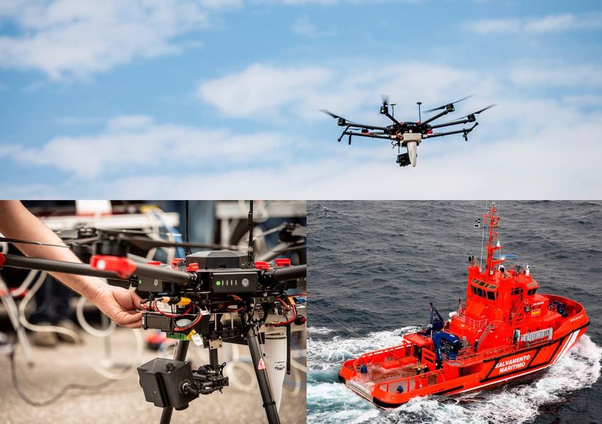
The digitalisation of maritime communications Study of the evolution of maritime communications: from voice to e-Navigation 1. Introduction This book gathers together all the information that we collected during a comprehensive study on maritime communications and the conclusions that can be drawn from that study. The emergence of new technologies in the early twentieth century caused a sharp increase in maritime trade, which led to more traffic and the consequent need to monitor such traffic. This was the backdrop to the appearance of the first communications systems for improving maritime safety, protection of the marine environment and/or the adjacent coastal area, and navigation efficiency. Whilst communications needs were initially met using beacons and other light-signalling devices, these systems were subsequently replaced by voice communication systems. Meanwhile, the passage of time and the consequent advances in technology led analogue communications to migrate to a digital scenario, which is where we can place today's systems, such as AIS, Satellite AIS, DSC and VDES. Today there is also a concern to engage in communications that are less trivial than the inconsequential or personal messages from a vessel to the members of the crew or passengers just mentioned. Such concerns mean that we must constantly review these ever-evolving communication systems. Our aim was to perform a study of communications at sea and collate all the available information related to this sector. In the chapters that follow, we aim to address all matters related to the various standards, guidelines and communications plans published to date, covering the most technical aspects to provide the reader with an overview. In addition, we will look at the different systems and technologies developed in this context, as well as the various projects concerning safety at sea, navigation and preserving the marine environment, to show clearly just how much communications have changed since digitalisation occurred. The organisations responsible for regulating the context of maritime communications include the ITU, IALA, IMO and COSPAS-SARSAT. Coordination and cooperation between these bodies is essential to ensure an effective approach to maritime communications and support their various developments. The ITU is the specialised telecommunications agency of the United Nations Organisation (UNO) tasked with regulating telecommunications internationally among the various administrations and regulators. The IALA is a non-governmental organisation that groups together the Lighthouse Services of most maritime countries worldwide, which are responsible for the supply and maintenance of lighthouses, buoys, radio-navigation systems and other aids to navigation. The IMO is the world authority responsible for setting standards for safety, protection and environmental behaviour to be observed in international maritime transport. Cospas-Sarsat is an element of the International Maritime Organization's Global Maritime Distress Safety System and is of great importance in search and rescue operations. This book has been prepared by GRADIANT with the collaboration of CELLNEX, both of which have prior experience and have made efforts in R&D in the maritime field. CELLNEX TELECOM is Europe's leading operator of wireless telecommunications and broadcasting infrastructures and classifies its activities into four areas: mobile telephony infrastructures, audiovisual broadcasting networks, security and emergency service networks and solutions for Page 5

The digitalisation of maritime communications
 Study of the evolution of maritime communications: from voice to e-Navigation

smart urban infrastructure and services management (Smart Cities and the "Internet of Things"
(IoT)).

CELLNEX has specialised in mobile, voice and data communications networks, aimed at closed
groups of users or fleets that require reliable service with a high level of availability. To achieve
this, it uses both analogue (PMR) and digital (DMR, TETRA) technologies and avails its clients of
over 9,000 sites distributed throughout Spain as well as specialised technical personnel and
capacity for around-the-clock supervision of centres for the efficient management of this type of
communications, even in crisis situations.

The company therefore has extensive experience in managing safety and emergency
communications networks and services, and its mobile radio systems serve more than 80,000
police officers, firefighters, forest rangers and healthcare personnel throughout Spain.

In September 2017, CELLNEX and the Spanish Maritime Rescue Company signed the "Provision of
services within the Global Maritime Distress and Safety System" for the Safety of Human Life at
Sea. Having won this contract through public tender, the company has continued to provide the
service, which was initially awarded in 2009.

CELLNEX provides this service through its network of shore stations to guarantee a 24/7
permanent listening service on the maritime frequency bands. The contract covers receiving
automatic alerts and distress calls, to be sent immediately to Maritime Rescue coordinators, as
well as transmitting information for maritime safety and meteorological information.

In 2009 the company installed and started up a communications network between the Maritime
Radio Communications Control Centres (CCRs), shore stations and Rescue Coordination Centres
(CCS's) of the Sociedad de Salvamento y Seguridad Marítima (Maritime Rescue and Safety
Company).

The services offered by CELLNEX TELECOM within the mobile communications framework are:
planning engineering, network design, operation and maintenance and supply and installation of
equipment.

As a Telecommunications Technology Centre, GRADIANT provides vision and knowledge in
telecommunication technologies to the processes and products that companies develop.

In the communications field, GRADIANT has extensive experience in the application of signal
processing techniques, both in analogue and digital radiofrequency subsystems. The Centre works
in research, design and implementation of satellite communication systems; developing
technologies aimed at solving the various challenges of the next generation of mobile systems; and
modelling, analysis and efficient operation of the electromagnetic spectrum.

The subsystems designed at GRADIANT make it possible to operate in different media, both
wireless and guided, terrestrial and satellite, to solve the needs linked to the communications that
arise in the different sectors. Likewise, the Centre performs activities related to implementing

 Page 6
The digitalisation of maritime communications
 Study of the evolution of maritime communications: from voice to e-Navigation

solutions for positioning and navigation systems and designs on-board systems based on
programmable devices, embedded platforms and sensors.

Another of the challenges facing GRADIANT is the increasing demand for the radio spectrum. Of
importance in this context is their work on cognitive radio and spectrum holes (white spaces) in
the UHF band, which include implementing spectrum monitoring schemes and developing geo-
referenced databases in the television band. Also of note are the technologies related to signal
analysis and monitoring and interference.

GRADIANT's work extends beyond communications and signal processing to cloud computing, data
analysis, security and privacy, IoT (Internet of Things) and biometrics. Thus, the Centre is clearly
positioned as a spearhead in terms of technological progress and R&D+I.

Both CELLNEX TELECOM and GRADIANT have several years' experience in R&D in the maritime
communications sector, participating in key projects such as ONDADA and POLARYS, which will be
mentioned in later chapters.

The ONDADA project was run by a consortium comprising the companies RETEVISIÓN (CELLNEX
group), EGATEL and SCIO, plus two research organisations: GRADIANT and the Integrated
Engineering Group from the University of A Coruña. This consortium was supported and funded by
the CDTI (Spanish Centre for Technological and Industrial Development) through the FEDER-
INNTERCONECTA-2011 programme (ITC-20113042). The main objective of the project, which ran
from January 2012 to December 2014, is to increase the coverage of the AIS network using
repeaters to allow a larger number of vessels to benefit from the system. In turn, this will facilitate
greater use of this system, making it useful not only for the safety of vessels, but also for people.

The POLARYS project was developed by a consortium led by RETEVISIÓN, with the participation of
BASTET SEGURIDAD TECNOLÓGICA, EGATEL, INSITU and SCIO, as well as the CINAE and GRADIANT
technology centres. The project ran for three years (2016-2018) and obtained the support and
financing of the CDTI through the FEDER INNTERCONECTA-2016 programme (EXP 00091271/ITC -
20161120). The aim of the project is to enhance maritime safety while increasing efficiency in
shipping and emergency management by developing a VDES (VHF Data Exchange System)
transceiver to exchange maritime safety information from one ship to another and between ships
and infrastructures. The development of this transceiver has a direct and immediate impact on the
limitations observed in the AIS platform while opening the door to the development of new
applications that previously seemed infeasible.

The contents to be covered throughout the following chapters are set out below. After this brief
introduction, Chapter 2 reviews the first communications systems and explains why there is a need
to modernise GMDSS. Chapter 3 presents the AIS, Satellite AIS and DSC systems, which are
evolutionary developments of the initial systems, and describes each one. Chapter 4 describes the
problems of AIS and the consequent appearance of VDES and sets out the characteristics of this
latter standard. Chapters 3 and 4 provide comments on some of the results of tests performed in
the POLARYS project to facilitate a better understanding of the systems described through
reference to real cases. This last section also introduces the e-Navigation concept and the state of

 Page 7
The digitalisation of maritime communications
 Study of the evolution of maritime communications: from voice to e-Navigation

the art in this field, defining how far we want to advance and the necessary starting point in order
to achieve it. Finally, Chapter 5 presents some conclusions concerning the analysis performed.

 Page 8
The digitalisation of maritime communications
 Study of the evolution of maritime communications: from voice to e-Navigation

2. The beginnings: analogue communications
2.1. Context
As we mentioned in the introduction, the emergence in the twentieth century of new technologies
such as radar (1935) and the LORAN system (1942) revolutionised maritime trade. The
considerable increase in traffic and the need for some kind of monitoring mechanism were to lead
to the first VTS (Vessel Traffic Services) in 1949. A VTS is based on a more or less extensive network
of radars, together with as much information as possible about the area concerned (electronic
chart, meteorological and oceanographic data, characteristics and conditions in which monitored
vessels are located, etc.) and a VHF-FM (Very High Frequency - Frequency Modulation) voice
communications network providing periodic reporting by each vessel on its position and the
reception of data by the info station. The main objectives of a VTS were to improve maritime
safety, protection of the marine environment and/or the adjacent coastal area, and efficiency of
navigation.

2.2. First analogue communications systems in the maritime field
The maritime domain uses multiple communications technologies across the radio spectrum to
support safe navigation, efficient operations and trade aspects. Below are listed the first
communications systems used in this context and their main characteristics.

2.2.1. LORAN-C
LORAN-C is a system of transmitting stations several hundred kilometres apart linked in chains.
One station within a chain is designated as the main (master) station and the others are secondary
stations. Each chain contains at least one master station and two secondaries to provide two
position lines. While LORAN-C is now obsolete, other systems such as e-Loran and research
projects are underway to evaluate the use of the LF spectrum.

Enhanced LORAN, also known as e-Loran, is the latest system to be developed, and makes full use
of 21st century technologies for low-frequency navigation. This system provides the modulated
data channel in the approximately 100 kHz signals. Two formats, known as Eurofix and 9th Pulse,
are currently available for this data channel. Both techniques offer data rates below 100 bps,
although higher rate concepts have been proposed.

 Figure 1: Example of LORAN-C Furuno receiver, extracted from [1]

 Page 9
The digitalisation of maritime communications
 Study of the evolution of maritime communications: from voice to e-Navigation

2.2.2. Voice communications in MF/HF
These types of communications provide a range from hundreds to thousands of kilometres. These
communications systems offer the possibility to initiate, receive, attend and maintain telephone
and radio conversations from both fixed equipment and mobile terminals.

General voice communication takes place in ship-to-ship, ship-to-shore and shore-to-ship modes
of operation across the band 1.6-26.5 MHz. Channel bandwidths are typically 3 kHz.

2.2.3. VHF voice communications
Voice communication using the VHF band (156.025-162.025 MHz) is prevalent, with ship-to-shore,
shore-to-ship and ship-to-ship communication also operating. Channel spacing is currently 25 kHz
although the use of 12.5 kHz channels on an interleaved basis is allowed. In this case the range is
of the order of tens or hundreds of kilometres.

It is used for distress, safety and general communications. Primary channels 6, 13 and 16 are used
for safety and distress communications.

 Figure 2: Example of Garmin 300i VHF fixed station, extracted from [2]

2.2.4. Locating Beacon
The principle of operation of a radio beacon is simple: When activated, the device sends
intermittent signals with the information that makes it possible to locate people or vessels in an
emergency.

 Page 10
The digitalisation of maritime communications
 Study of the evolution of maritime communications: from voice to e-Navigation

The frequency 121.5 MHz is an aeronautical emergency frequency. 121.5 MHz radiobeacons were
developed in the mid-seventies for installation on aircraft, as Emergency Locator Transmitters
(ELTs). However, they can also be used on board ship as part of Emergency Position-Indicating
Radio Beacons (EPIRBs) or in Personal Locator Beacons (PLBs).

 Figure 3: Example of automatic McMurdo
 SmartFind G8 emergency beacon, taken from [3]

2.2.5. Voice communications in UHF
Manual and fixed UHF radios are normally used in vessels for on-board communications, among
crew members, port workers or operators with related posts. These radios are usually limited to
radiating less than 2 W in the 450 470 MHz band and are used for voice and data communication.

 Page 11
The digitalisation of maritime communications
 Study of the evolution of maritime communications: from voice to e-Navigation

 Figure 4: Example of UHF radio for TechBrands
 internal communications, extracted from [4]

2.2.6. Radar
Radar systems typically operate in two bands: S-band from 2.9 to 3.1 GHz and X-band from 9.2 to
9.5 GHz. The radars are used for target detection and to support identification and for coastal and
port navigation. These bands are also used by radar transponders for search and rescue (RACON,
SART) RACONs are maritime radar signal transponders that are used to improve object detection.
SART radars are devices for locating ships in distress through the creation of a series of points on
the radar screen of a rescue ship.

 Figure 5: Example of Rescuer 2 SART Plastimo
 transponder, extracted from [5]

 Page 12
The digitalisation of maritime communications
 Study of the evolution of maritime communications: from voice to e-Navigation

2.3. Other communications systems
Although the main communication systems are discussed in Section 2.2 to contextualize and
address the various systems related to maritime safety and distress communications, others are
mentioned here to allow the reader to appreciate more clearly the advantages of the technologies
described later in chapters 3 and 4.

2.3.1. NAVTEX
NAVTEX is an automated system for instantly distributing Maritime Safety Information such as
maritime navigational warnings, weather forecasts and warnings, search and rescue notices and
similar information to ships.

The frequency of NAVTEX messages varies by language used. Messages are broadcast in English
on 518 kHz, while 490 kHz and 4209.5 kHz are used to broadcast in English and/or local language.
The messages are coded and the time of broadcasting is internationally coordinated by areas to
share the same frequency.

 Figure 6: Example of NASA Easy NAVTEX receiver, extracted from [6]

2.3.2. NBDP
NBDP (also known as radio telex) is a technique which automates radio signals to telegraphy. It is
FSK modulated onto HF channels of 0.5 kHz and supports low speed data transmissions (100 bps)
in the maritime mobile service bands within 1.6-26.5 MHz.

NBDP is an element of GMDSS and can be used as the text-based distress follow-up
communications and general communications between ship-to-ship, ship-to-shore and shore-to-
ship, especially to overcome the language difficulties. The use of NBDP for general communication
is declining and is now used for position reporting from ships and promulgation of meteorological
warnings and forecasts from shore stations. The IMO has indicated that radio telex may no longer
be considered a required system within GMDSS.

 Page 13
The digitalisation of maritime communications
 Study of the evolution of maritime communications: from voice to e-Navigation

 Figure 7: Example of NASA radio telex, extracted from [7]

 2.3.2. Summary Tables

 Tables 1, 2 and 3 show a summary of all the systems discussed in this chapter, both in this and the
 previous section, together with the most significant characteristics of each one.

 Channel Bandwidth
 System Band Service Purpose
 frequency data rate
 MF/HF voice MF/HF 2,182 kHz 3 kHz Mobile to Distress
communications 4,125 kHz mobile. Communication
 6,215 kHz Mobile to
 8,291 kHz fixed.
 12,290 kHz Fixed to
 16,420 kHz mobile.
 VHF voice VHF 156,300 MHz 25 kHz Mobile to Distress
communications 156,650 MHz mobile. Communication
 156,800 MHz Mobile to
 fixed.
 Fixed to
 mobile.
Locating Beacon VHF 121,5 MHz Mobile to Location
 mobile.
 SART 9.2 - 9.5 GHz Mobile to Location of
 mobile. objectives
 Table 1: Main systems for distress communications in the maritime field [8]

 Page 14
The digitalisation of maritime communications
 Study of the evolution of maritime communications: from voice to e-Navigation

 Channel Bandwidth
 System Band Service Purpose
 frequency data rate
 HF voice MF/HF 1.6,25.5 MHz 3 kHz Mobile to General voice
communications mobile. communications
 Mobile to
 fixed.
 Fixed to
 mobile.
 VHF voice VHF 156.025 MHz 25 kHz Mobile to General voice
communications mobile. communications
 Mobile to
 fixed.
 Fixed to
 mobile.
 NBDP MF/HF 1.6,25.5 MHz 0.5 kHz Mobile to General text
 mobile. communication
 Mobile to
 fixed.
 Fixed to
 mobile.
 On-board UHF 457.5125 – Mobile to On-board
communications 457.5875/ mobile. communications
 467.5125 MHz Internal
 communicatio
 n
 Table 2: Main systems for general communications [8]

 Page 15
The digitalisation of maritime communications
 Study of the evolution of maritime communications: from voice to e-Navigation

 Channel Bandwidth
 System Band Service Purpose
 frequency data rate
 NAVTEX MF/HF 518 kHz 0.5 kHz Fixed to Receipt of
 490 kHz mobile. maritime safety
 4,209.5 kHz information

 NBDP HF 4,210 kHz 0.5 kHz Mobile to Receipt of
 6,314 kHz mobile. maritime safety
 8,416.5 kHz Mobile to information
 12,509 kHz fixed.
 16,806.5 kHz Fixed to
 19,880.5 kHz mobile.
 22,376 kHz
 26,100.5 kHz
 LORAN LF 90 kHz Fixed to Positioning
 mobile.
 VHF voice Mobile 156.025 MHz 25 kHz Mobile to Communication
communications VHF mobile. for navigational
 Fixed to and safety
 mobile. related
 Mobile to purposes
 fixed.
 Radar S Band 2.9-3.1 GHz Mobile and Collision
 fixed avoidance,
 Navigational
 aid.
 Radar X Band 9.2-9.5 GHz Mobile and Collision
 fixed avoidance,
 Navigational
 aid.
 RACON 2.9-3.1 GHz Fixed Navigational aid
 9.2-9.5 GHz
 Table 3: Main systems for the promulgation of Maritime Safety Information [8]

 2.4. Need to modernise GMDSS
 The challenge facing radio communication in the maritime sector is the need to relay more
 information, which puts pressure on the availability of spectrum. As a finite resource, spectrum is
 under increasing demand from all users globally.

 The current GMDSS system was designed at the end of the nineteen seventies and, until just a few
 years ago, there was no intention to review it. The technology has developed significantly in that
 time, and elements within the GMDSS have also evolved, although the initial functions remain
 unchanged.

 In these circumstances, there is a need to switch from analogue to digital and from voice to data
 to allow the effective and efficient sharing of large amounts of data by a great many users.

 Page 16
The digitalisation of maritime communications
 Study of the evolution of maritime communications: from voice to e-Navigation

Therefore, to maintain all the priorities and uses for radiocommunications that are still required,
as is the case for distress alerts and warning messages or emergency and safety communications,
the modernisation of GMDSS focuses on the following aspects:

On the one hand, the idea is to simplify drafting of the documentation, to facilitate the
compression of GMDSS for seafarers, crew members and coastal authorities, and to any entity
directly or indirectly linked to the maritime sector.

On the other hand, it seeks to introduce into the system any emerging and new technologies that
may appear in the future, to integrate mobile satellite systems such as Iridium or Thuraya and lay
the foundations of the e-Navigation concept to run it.

Another issue involved in the modernisation of GMDSS is reviewing the definition of the marine
area.

 Page 17
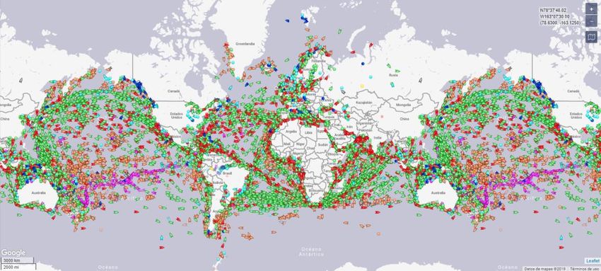
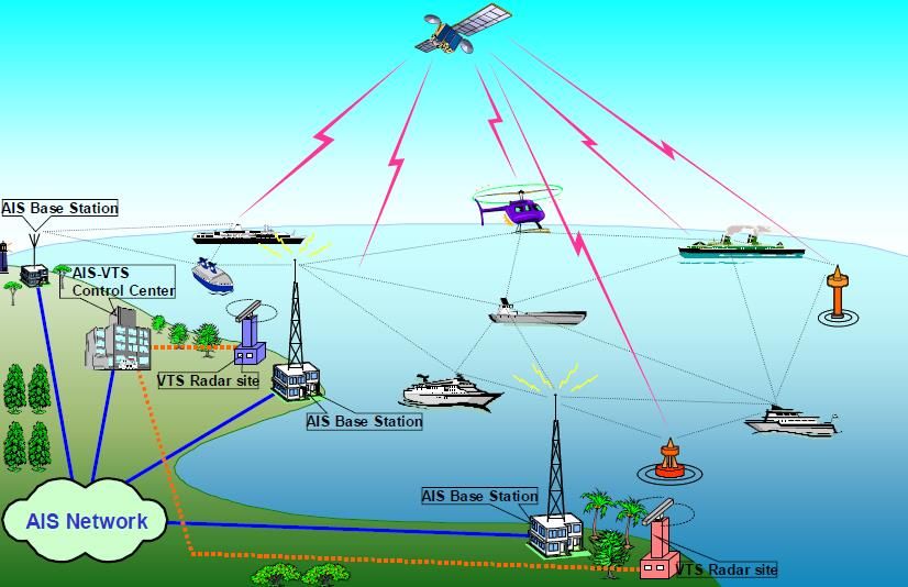
The digitalisation of maritime communications Study of the evolution of maritime communications: from voice to e-Navigation 3. Present: digital communications 3.1. Evolution of initial systems The fact that communications are made by voice has led to serious accidents over the years. Statistics estimate that between 75% and 96% of total maritime accidents are the result of human error [9]. Radars, on the other hand, also have inherent limitations that cause a small number of disasters. They become less effective in adverse conditions and they do not provide an effective response to obstacles such as an islet or a rock. These circumstances, and the intention to renew the GMDSS system, caused the IMO to study the need for a complementary autonomous system that also provides the ability to communicate between ships, in addition to the radiocommunications to the land station, leading to AIS. 3.2. AIS 3.2.1. Introduction AIS is a broadcast communications system operating in the VHF band assigned to maritime mobile services (156.025 MHz-162.025 MHz). This technology allows exchanges of navigation information both ship-to-ship and ship-to-shore control stations. AIS uses an open protocol for the exchange of navigation data in the access to the medium is provided as variants of TDMA. The information exchanged between the various entities is transmitted over 26.66 ms slots, which corresponds to 256 bits (guard intervals + flags + data) at a bit rate of 9.6 kbps. This value is more than sufficient, since the type of data transmitted corresponds to basic parameters such as speed, position, identification or direction. One of the greatest advantages of AIS over radar technology is the possibility to contact a ship with which there is no direct vision, since it can avoid obstacles. Furthermore, the data received do not give rise to false positives (rocks, waves, etc.). Despite this, AIS is always considered as a complementary, rather than a supplementary technology. The AIS system emerged as an attempt to improve maritime safety. However, its applications have been shown to help improve navigation efficiency and environmental protection. An example of an AIS network is shown illustratively in Figure 8. 3.2.2. Applications At present, the main applications of AIS are: Providing weather and navigation information. Improving port planning. Facilitating communications. Enabling efficient navigation. Providing support to assistance systems in search and rescue or accident investigation. Environmental protection. Page 18
The digitalisation of maritime communications Study of the evolution of maritime communications: from voice to e-Navigation Figure 8: Example of an AIS network [10] 3.2.3. Mandatory use Numerous international organisations such as IMO, IALA, ITU and IEC worked together to help design the AIS system, which took place in the mid-1990s. In addition, great contributions were made by entities from Sweden and Finland, which were fundamental for the development of the SOTDMA mode. In subsequent years, to improve safety in maritime transport, the IMO established requirements related to cargo type and tonnage to the effect that all vessels meeting these requirements install the AIS system on a mandatory basis. These requirements, extracted from [11], are as follows: For ships built from 1 July 2002: AIS must be fitted aboard all passenger ships, cargo ships of 300 GT and upwards engaged on international voyages and cargo ships of 500 GT and upwards not engaged on international voyages. For ships built before 1 July 2002 and engaged on international voyages: passenger ships and tankers are granted 1 year for installation (not later than 1 July 2003) and cargo ships from 2 to 5 years depending on gross tonnage (1 July 2004 for 50,000 GT and over and 1 July 2007 for those between 300 and 3,000 GT). Ships engaged on international voyages built before 1 July 2002: 1 July 2008 is the deadline for the installation of AIS. In 2012, around 70,000 ships were equipped with AIS worldwide and it was estimated that the future figure would reach 150,000 [12]. 3.2.4. System overview Next, we shall describe in detail the salient aspects of the AIS system, while providing an overview at the same time. Page 19
The digitalisation of maritime communications Study of the evolution of maritime communications: from voice to e-Navigation 3.2.4.1. Classes of AIS stations There are several classes of AIS devices or stations, which are grouped into two categories: Mobile stations: These are generally devices located on ships. Various types of stations fall within this classification: o Class A: equipment on ships meeting IMO requirements. They have minimal equipment, such as a keyboard and a screen. Transmit output power is 12.5 W. o Class B: devices compatible with those in Class A but installed on vessels that do not comply with IMO restrictions (for example, pleasure craft). Two variants have been defined depending on whether the media access mode is CSTDMA (Class B 'CS') or SOTDMA (Class B 'SO’). Their transmit output power is 2 W, and therefore they have a lower range than Class A equipment. The market price is also lower. o SAR: station used by an aircraft in a search and rescue situation. o SART: device designed to transmit only. An example of this is the emergency beacon (MOB or Man-Over-Board scenario). o AIS receiver: a cheaper option for “non SOLAS” vessels wishing to monitor AIS traffic. They have only receiver circuits, so they cannot be seen by the other AIS stations. Fixed stations: These are installed in a fixed location, such as on shore or on a buoy. There are several types: o Base station: used by the competent authorities for the efficient management of the VDL (VHF Data Link). o AtoN: a device designed to improve safety and efficiency in navigation. They range from signalling beacons to buoys that report sea conditions: meteorology, waves, etc. o Repeater: an element used to extend the range of other AIS stations. 3.2.4.2. Types of information and transmission periods AIS messages may contain the following types of information, each with its corresponding transmission rate: Static: information associated with parameters that do not change over time, such as the name of the ship, its dimensions, etc. Sent every 6 minutes or when requested by another station. Dynamic: data provided by the ship's sensors (speed, direction, turning rate, latitude and longitude, etc.). Tables 4 and 5 show the transmission slots for this type of information according to the type of station and speed. Voyage related: information on the navigation status (destination, estimated time of arrival, type of cargo, draught, etc.). Follows the same shipping period as static information. Safety-related: ASCII text to warn of any anomaly or danger. Transmitted whenever necessary. Page 20
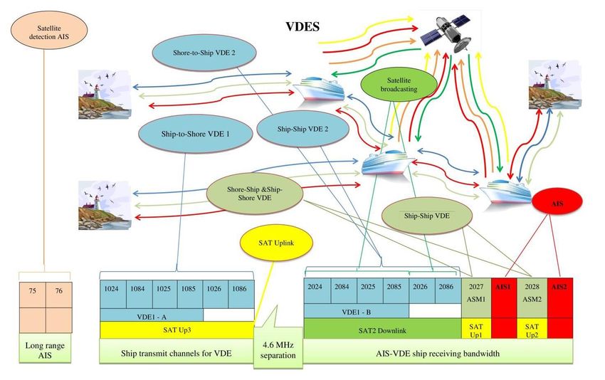
The digitalisation of maritime communications
 Study of the evolution of maritime communications: from voice to e-Navigation

 Dynamic changes in vessel Nominal transmission period
 movements
 At anchor or moored and speed 3 knots 10 s
 Speed between 0-14 knots 10 s
 Speed between 0-14 knots and changing course 3.33 s
 Speed between 14-23 knots 6s
 Speed between 14-23 knots and changing course 2s
 Speed >23 knots 2s
 Table 4: Transmission period for a Class A vessel [13]

 Station conditions Nominal transmission period
 Class B 'SO' with speed 23 knots 5s
 Class B 'CS' with speed 2 knots 30 s
 Search and Rescue aircraft 10 s
 Aids to navigation 3 min
 AIS base station 10 s
 Table 5: Transmission period for another type of station [13]

 3.2.4.3. Mode of operation
 With the exception of devices designed solely to transmit or receive, every AIS station must be
 able to receive simultaneously from two channels in parallel and transmit alternately on those
 channels. This mechanism is known as dual channel operation. This requires two receiver circuits
 and one transmitter1.

 Alternating transmissions between two channels mitigates the harmful effects of RF interference
 and balances the load between those channels.

 Because AIS is a simplex service, as TDMA techniques do not allow transmitting and receiving
 simultaneously on the same channel, transmission is prioritised over reception.

 3.2.4.4. Frequency aspects
 For the AIS service, the ITU has defined two worldwide channels within the maritime VHF band
 (156.025-162.025 MHz). These channels are AIS 1 and AIS 2, centred on 161.975 MHz and 162.025
 MHz respectively, with a bandwidth of 25 kHz.

 Simplex and duplex channels are assigned within this frequency band2. Duplex channels comprise
 two frequencies - one for transmissions from ships (reception by the shore station) and the other

1
 Some AIS stations have a third receiver, used to receive DSC (Digital Selective Calling) commands. The DSC
standard (channel 70) is the core of GMDSS and complements the services offered by AIS.

2
 A device is said to operate on a simplex channel when it uses the same frequency for transmitting and receiving
information. Whereas a device operates on a duplex channel when the frequency at which it transmits is different
from the frequency at which it receives the information.

 Page 21
The digitalisation of maritime communications Study of the evolution of maritime communications: from voice to e-Navigation for transmission from the shore station (reception by ships). For example, marine VHF channel 87 consists of frequencies 157.375 MHz and 161.975 MHz, for transmissions from ships and shore stations respectively (see Annex 4 of [14]). This explanation serves as a link to clarify the numbering method used when a duplex channel is used for a simplex service, such as AIS, where channels AIS 1 and AIS 2 correspond to the shore frequencies of channels 87 and 88. Following this approach, the procedure determines that AIS 1 can be numbered as 2087 or 87B and AIS 2 as 2088 or 88B. If the frequencies of the simplex channel were associated with transmissions from ships, the prefix '20' would be replaced by '10' and the suffix 'B' with 'A’. See Figure 9. In summary, AIS stations should be designed to operate across the entire VHF maritime mobile band, although two simplex channels have been assigned by default for the international use of AIS. Both channels have a bandwidth of 25 kHz: AIS 1 (Channel 87B, 161,975 MHz) (numbering 2087): primary channel. AIS 2 (Channel 88B, 162,025 MHz) (numbering 2088): secondary channel. Should one of these two channels be unavailable, either because the local authorities have assigned it to another service or because interferences make it impossible to use, then alternative channels must be selected using channel management techniques. One frequency-related characteristic is stability in the carrier frequency. This parameter must be lower than ± 500 Hz, both for the transmitter and the receiver. Figure 9: Excerpt from the frequency table of Rec. ITU-R M.1084-5 3.2.4.5. Physical layer blocks This section contains the essential aspects associated with the blocks of the physical layer: Data encoding: Encoding is NRZI type. An NRZI signal transits between voltage levels when the bit to be transmitted is a '1' and remains at the same level when the bit is a '0’. No additional FEC techniques are used, nor other physical layer blocks such as bit interleaver or bit scrambler. Page 22
The digitalisation of maritime communications Study of the evolution of maritime communications: from voice to e-Navigation Figure 10: NRZI coding example Modulation: GMSK/FM is used. A Gaussian low pass filter is placed before the frequency modulator to compact the MSK spectrum. The MSK modulation index: h = 0.5 is used. Figure 11: Block diagram of a GMSK-FM modulator BT (Bandwidth x Time) product: the relation between the bandwidth of the Gaussian filter at -3 dB and the bit rate. The values used in AIS are BT = 0.4 for the transmitter and BT = 0.5 for the receiver. Binary rate The binary rate for AIS is 9.6 kbps ± 50 ppm. Transmit output power 1 - 12.5 W depending on the device. Carrier power tolerance must be in the range ± 1.5 dB. Spectrum mask The characteristics of the spectrum mask are: -25 dBc @ ±10 kHz y -70 dBc @ ±25 kHz. 3.2.4.6. Format of an AIS package An AIS package consists of 256 bits (guard intervals + flags + data) and its structure is inherited from the HDLC protocol [15]. The format in Figure 12 corresponds to that used to transmit most messages. However, there are scenarios (Class B 'CS' devices, long-range transmissions, messages that need more than 1 slot, etc.) where package fields are adapted to meet the particular context. Figure 12: Default format of an AIS package Page 23
The digitalisation of maritime communications
 Study of the evolution of maritime communications: from voice to e-Navigation

 3.2.4.7. AIS messages
 27 messages have been defined in the current AIS specification [13] for the operation of the
 system. These messages carry the four possible types of existing information discussed in Section
 3.2.4.2: static, dynamic, voyage related and safety.

 Each of the 27 messages is briefly specified in Table 6. For a more detailed explanation, please see
 Annex 8 of [13].

Number Message Purpose
 1–3 Position reports Position messages to be sent periodically by Class A mobile
 stations.
 4 Base station report A message sent periodically by the base station to inform
 about its position and temporary data.
 5 Ship static and voyage A message used by Class A equipment and SAR aircraft to
 related data report static or voyage related data.
 6 Addressed binary message A message addressed to a specific station to warn of
 certain information. The length of this type of message
 varies between 1 and 5 slots, which translates into a
 maximum of between 8 and 117 bytes of binary data.
 7 Binary acknowledge A message used to agree to one or more '6’ messages. It
 must be transmitted on the same channel through which
 that message was received.
 8 Binary broadcast message Similar to message '6', but for broadcast transmissions .
 9 Standard SAR aircraft A message used by aircraft in SAR situations. By default, it
 position report is sent every 10 seconds.
 10 UTC and date inquiry A message used when one station requests temporary
 information from another.
 11 UTC and date response Response to message '10’. Shares format with message '4’.
 12 Addressed safety related A message similar to '6' for sending safety related text.
 message
 13 Safety related A message used to agree to one or more '12’ messages. It
 acknowledgement must be transmitted on the same channel through which
 that message was received.
 14 Safety related broadcast Similar to message 12, but for broadcast transmissions.
 message
 15 Interrogation A message for requesting information other than that
 requested by message '10’. The response must be
 transmitted on the same channel through which the
 request is received.
 16 Assigned mode command A base station can assign to another AIS station a
 transmission schedule different to the one it already has.
 The new schedule must have been previously reserved by
 the base station through message '20’.
 17 GNSS broadcast binary A message transmitted by that base station that is
 message connected to a DGNSS signal, allowing the rest of the
 stations to calculate their position more accurately.

 Page 24
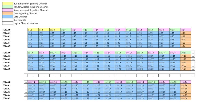
The digitalisation of maritime communications Study of the evolution of maritime communications: from voice to e-Navigation Number Message Purpose 18 Standard Class B A message similar to '1', '2' and '3', but for Class B devices. equipment position report 19 Extended Class B A backup to message '18', with a longer period. equipment position report 20 Data link management A message used by base stations to notify of slots already message occupied by stations that have a fixed transmission schedule. 21 Aids-to-navigation report A message used by an AtoN station to report its functionality. 22 Channel management A message transmitted by a base station to notify the VHF radiocommunications parameters assigned to a specific geographical area. 23 Group assignment A message allowing a base station to assign a set of command operating parameters to a specific class of AIS stations. 24 Static data report A message that allows any AIS station to associate an MMSI to its name, which is 20 6-bit characters maximum in length. 25 Single slot binary message A message similar to '6' and '8', but length is limited to 1 slot. 26 Multiple slot binary A message allowing the transmission of up to 5 slots with message with binary data to be planned. communication state 27 Long-range AIS broadcast A message similar to '1', '2' and '3', but for long-range message applications such as Satellite AIS. It is oriented to Class A equipment. Table 6: List of AIS messages 3.2.4.8. TDMA access modes As mentioned above, AIS devices operate on two channels of the VHF maritime mobile band. By default, these channels are AIS 1 (161.975 MHz) and AIS 2 (162.025 MHz). TDMA (Time Division Multiple Access) techniques are used to allow access to multiple users, with a duration for each slot of 26.66 ms. This figure means 2,250 slots per channel per minute. A group of 2,250 slots comprise a frame (see Figure 13). The access period required for each station will depend on the type of information to be transmitted, and varies from two seconds for dynamic information (messages 1 - 3) in scenarios in which the ship sails at more than 14 knots, up to six minutes when the information is static or voyage type (message 5). Synchronisation at slot and frame level is required to correctly access the medium. This is achieved thanks to two factors: A precise time reference such as GPS or another GNSS system. The 'communication state' field information present in some messages. Page 25
The digitalisation of maritime communications Study of the evolution of maritime communications: from voice to e-Navigation If it has no direct access to the time reference, the AIS device must synchronise to another device that does, or failing that, to the AIS station (which could be a base station) with the largest number of incoming connections (known as a semaphore). Because part of the AIS devices operate outside the coverage range of the base station controlling them, for example out to sea, the first TDMA technique designed was SOTDMA (Self-Organizing TDMA). Equipment uses this mode to create its slot reservation schedule The underlying premise for establishing this scheme is to prevent its transmissions from colliding with those of other devices within range. This technique is used mainly in Class A equipment. Figure 13: AIS TDMA system [16] Other access methods interoperate with SOTDMA and are used in different types of AIS devices. These methods are: RATDMA (Random Access TDMA). ITDMA (Incremental TDMA). FATDMA (Fixed Access TDMA). CSTDMA (Carrier Sense TDMA). Modified SOTDMA. Before we introduce these different schemes, we would like to refer to two related concepts that make them easier to explain later on: mode of operation and candidate slot. 3.2.4.8.1. Mode of operation An AIS device can work in three modes of operation: Autonomous or continuous: the station determines its own schedule for transmission and should therefore automatically resolve scheduling conflicts with other stations. Assigned: In certain scenarios, the competent authority, through the base station, may decide that a device should transmit under a specific transmission schedule, specified using message 16. In this mode of operation, a Class A device will report its position with message 2, rather than with message 1. Page 26
The digitalisation of maritime communications Study of the evolution of maritime communications: from voice to e-Navigation Polled: As a coastal monitoring measure, a station can be interrogated via message 15 about the type of ship and its cargo. The response should be transmitted on the channel where the interrogation message was received and should never conflict with the integrity of the other two modes. This response is made using messages 3 and 5. Not all types of AIS stations allow all three modes of operation (see the following Table). Class Class AtoN AtoN AtoN Limited Class Base Station type B B type type type Repeater SART SAR base A station 'SO’ 'CS’ 1 2 3 station Mode of operation Autonomous C C C C C C C C C C C Assigned C C C N N N N N N C C Polled C C C N N N C N N C C C = Allowed in any configuration. N = Not allowed. Table 7: Relationship between the types of stations and the modes of operation [17] 3.2.4.8.2. Candidate slot Stations that present one of the schemes mentioned at the beginning of the section require a phase for monitoring both AIS channels. The aim is to determine their activity, participating users, position, assignment of slots and the existence of shore stations. This information is used to create a dynamic memory (slot map) to store the status of slots, providing a starting point to establish the transmission scheme of each station. The slots used for transmission are chosen randomly from a set of special slots, known as candidate slots, belonging to the selection interval. This interval consists of a series of consecutive slots whose duration varies according to the TDMA method used. For example, for RATDMA the selection interval is set to 150 slots (4 seconds). While candidate slots are being selected to broadcast on one channel, the activity of the other channel is also taken into account. First, all slots free on both channels are determined as candidate slots. Next, if fewer than four slots meet this condition, the station should intentionally reuse slots. The reason for intentionally reusing slots to maintain a minimum of four candidate slots is to provide a high probability of access to the radiocommunications, while relieving congestion. In this process, the state of each slot has an influence on both channels and the limit of 120 nautical miles from the base station. Reusing slots reduces the size of the AIS cell, ensuring that the position messages from the nearest ships (those that are really relevant for safe navigation) are not affected. If slot reuse is required, the candidate slots must meet any of the five conditions or rules defined for this process (sub-section 4.4.1 of Annex 2 of [13]), to be applied in descending order of priority until four candidate slots are complete or until the slots of the selection interval have been used. 3.2.4.8.3. Self-Organizing TDMA - SOTDMA SOTDMA is the most complex access scheme of all those defined for AIS. The aim of this mode is to offer an access algorithm to resolve possible collisions without the intervention of a central Page 27
The digitalisation of maritime communications
 Study of the evolution of maritime communications: from voice to e-Navigation

 station. To do this, each SOTDMA station announces in advance which slots future transmissions
 will be made in. This allows the rest of the stations to be consistent with that reservation pattern.

 By and large, the messages transmitted under this access mode are of a periodic nature and inform
 about the position of the ship.

 These reservations are given in the
 Communication State field

 Ship A transmits on
 this time slot while
 reserving another
 for the next
 position message

 SOTDMA region
 (normally 40 NM)

 Figure 14: Access and reservation of slots for SOTDMA equipment

 3.2.4.8.4. Random Access TDMA - RATDMA
 This access mode is used when a slot that has not been previously announced needs to be
 reserved. Examples of this are reserving the first slot when entering the network of a SOTDMA
 device and transmissions of non-periodic messages (text messages or retransmissions from a
 simplex repeater).

 RATDMA is not suitable for periodic transmissions because it would produce a significant number
 of collisions, since the rest of the stations do not know what slots are reserved by RATDMA
 equipment.

 3.2.4.8.5. Incremental TDMA - ITDMA
 ITDMA is used when a station needs to report a temporary change in the dissemination rate of its
 periodic messages, notify the intention to transmit a specific (non-periodic) message, such as
 security-related messages, or in the network entry phase3. This allows the device to inform the
 rest of the stations of its slot reservations.

 3.2.4.8.6. Fixed Access TDMA - FATDMA
 AIS devices that operate according to FATDMA transmit in a series of predefined slots only. These
 slots are assigned by the competent authorities and sent to the rest of the system via the base
 stations using message 20.

3
 During this phase, the first slot must be reserved using RATDMA.

 Page 28
You can also read