The Very High Temperature Reactor: A Technical Summary - Revision 0 June 2004
←
→
Page content transcription
If your browser does not render page correctly, please read the page content below
Revision 0
                                   June 2004

The Very High Temperature Reactor:
      A Technical Summary

                Prepared for

            MPR Associates, Inc.
               320 King Street
            Alexandria, VA 22314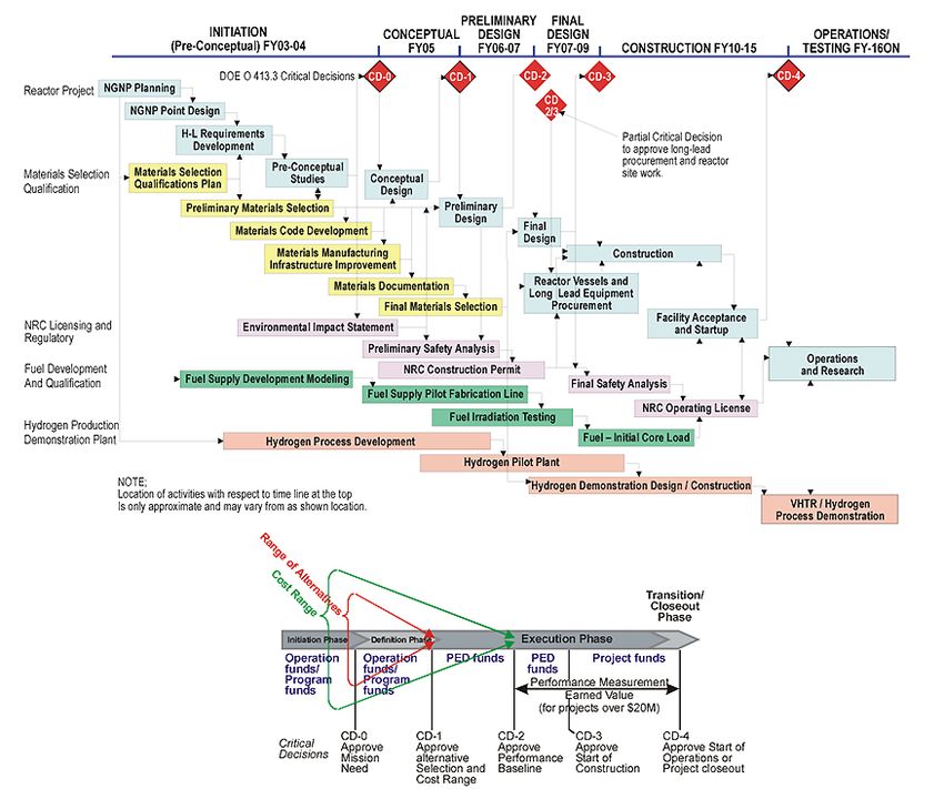
The Very High Temperature Reactor:
            A Technical Summary

Revision 0

June 2004

Principal Contributors
Doug Chapin
Scott Kiffer
Jim Nestell

Prepared for
MPR Associates, Inc
320 King Street
Alexandria, VA 22314

                                           2
Revision 0
Contents

1       Introduction........................................................................................................ 1-1

        1.1    Background............................................................................................................... 1-1
        1.2    Purpose ..................................................................................................................... 1-2
2       The Very High Temperature Reactor................................................................ 2-1

        2.1    Design Basis ............................................................................................................. 2-1
        2.2    Reactor...................................................................................................................... 2-2
        2.3    Power Cycle.............................................................................................................. 2-4
        2.4    Fuel and the Fuel Cycle ............................................................................................ 2-4
        2.5    Balance of Plant........................................................................................................ 2-6
               2.5.1 Primary Heat Transfer Loop ........................................................................... 2-6
               2.5.2 Secondary Heat Transfer Loop ....................................................................... 2-7
               2.5.3 Reactor Cavity Cooling System ...................................................................... 2-7
               2.5.4 Other BOP Equipment .................................................................................... 2-8
        2.6    Hydrogen Production Using Nuclear Process Heat.................................................. 2-9
               2.6.1 Steam Reformation.......................................................................................... 2-9
               2.6.2 Electrolysis...................................................................................................... 2-9
               2.6.3 Thermochemical Cycles................................................................................ 2-10
        2.7    Other Process Heat Applications ............................................................................ 2-11
        2.8    Safety and Proliferation Resistance ........................................................................ 2-12
3       Technical Challenges ........................................................................................ 3-1

        3.1    Fuel ........................................................................................................................... 3-1
        3.2    Materials ................................................................................................................... 3-2
               3.2.1 Material Properties Database .......................................................................... 3-3
               3.2.2 VHTR Service Conditions .............................................................................. 3-4
               3.2.3 Component Material Challenges..................................................................... 3-6
        3.3    Balance of Plant........................................................................................................ 3-7
               3.3.1 Turbomachinery .............................................................................................. 3-7

Revision 0
                                                                                                                                               iii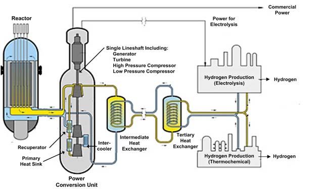
Contents (cont’d.)

               3.3.2 Intermediate Heat Exchanger.......................................................................... 3-7
               3.3.3 Helium Purification & Magnetic Bearings ..................................................... 3-8
        3.4    Process Heat Applications ........................................................................................ 3-8
               3.4.1 Hydrogen Production Issues ........................................................................... 3-8
               3.4.2 VHTR Interface Issues.................................................................................... 3-9
        3.5    Modeling, Analysis, and Licensing Issues ............................................................. 3-11
4       R&D Programs ................................................................................................... 4-1

        4.1    The GIF VHTR Roadmap ........................................................................................ 4-1
        4.2    The U.S. NGNP Roadmap........................................................................................ 4-2
5       References ......................................................................................................... 5-1

A       Acronyms and Abbreviations .......................................................................... A-1

B       Brief Survey of Gas-Cooled Reactor Designs ................................................ B-1

        1.     Early Gas-Cooled Reactors.......................................................................................B-1
        2.     Prototype HTGRs .....................................................................................................B-2
        3.     Demonstration HTGRs .............................................................................................B-2
        4.     HTGR Test Facilities................................................................................................B-3
        5.     Near-Term HTGRs ...................................................................................................B-3
               5.1. The GT-MHR..................................................................................................B-3
               5.2. The PBMR ......................................................................................................B-4
        6.     Beyond the VHTR ....................................................................................................B-5
C       Brief Description of Other Generation IV Reactors ....................................... C-1

        1.     The Gas-Cooled Fast Reactor (GFR) .......................................................................C-2
        2.     The Lead-Cooled Fast Reactor (LFR) ......................................................................C-2
        3.     The Molten Salt Reactor (MSR)...............................................................................C-2
        4.     The Sodium-Cooled Fast Reactor (SFR)..................................................................C-2
        5.     The Supercritical Water-Cooled Reactor (SCWR)...................................................C-3

                                                                                                                                    iv
Revision 0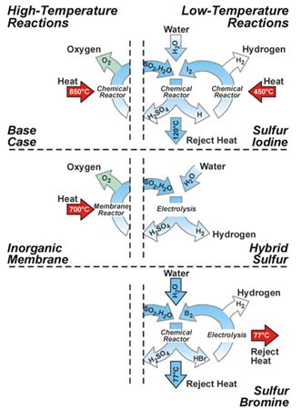
Tables
Table A-1. Acronyms and Abbreviations .................................................................................. A-1
Figures
Figure 2.1-1. The NGNP Reactor Layout (Ref. 18) .................................................................... 2-1
Figure 2.2-1. The GT-MHR Reactor Core (Prismatic VHTR Reference Core) (Ref. 15) .......... 2-2
Figure 2.4-1. TRISO (Triple Isotropic) Coated Fuel Particle (Ref. 11) ..................................... 2-4
Figure 2.5-1. NGNP Primary Heat Transfer Loop ...................................................................... 2-6
Figure 2.5-2. NGNP Secondary Heat Transfer Loop .................................................................. 2-7
Figure 2.5-3. GT-MHR Passive RCCS and Peak Accident Core Temperatures (Ref. 19).......... 2-8
Figure 2.6-1. Sulfur-Based Thermochemical Cycles (Ref. 14) ................................................ 2-10
Figure 2.7-1. Nuclear Process Heat Applications and Required Temperatures (Ref. 4) .......... 2-11
Figure 2.8-1. VHTR Peak Temperatures During Accident (Ref. 23)........................................ 2-12
Figure 3.1-1. SiC Coated Fuel Particle Temperature Capability (Ref. 19).................................. 3-2
Figure 3.2-1. Increased Reaction/Diffusion Rates for the VHTR ............................................... 3-5
Figure 4.1-1. The GIF VHTR R&D Timeline (Ref. 2)................................................................ 4-1
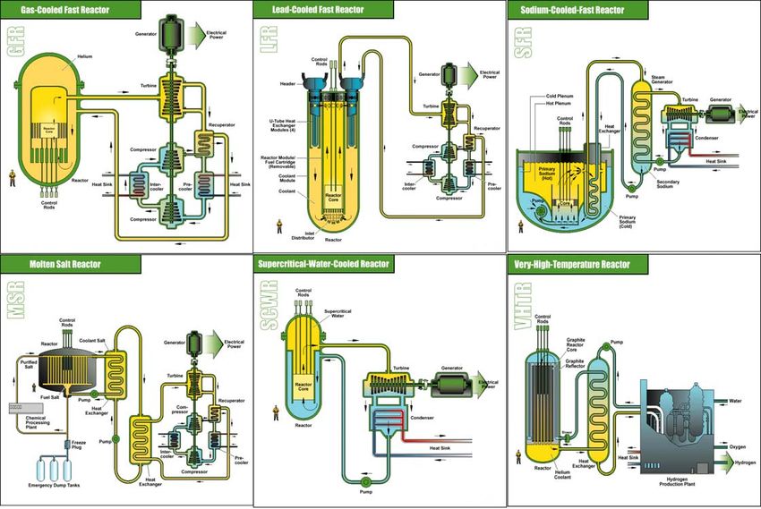
Figure 4.2-1. The U.S. NGNP Development Roadmap (Ref. 14) ............................................... 4-3
Figure 4.2-1. HTGR Coolant Outlet Temperatures .....................................................................B-1
Figure 4.2-2. The GT-MHR by General Atomics (Ref. 6) ..........................................................B-4
Figure 4.2-3. The Pebble Bed Modular Reactor (PBMR) by PBMR (Pty.), Ltd. (Ref. 6) ..........B-5
Figure 4.2-4. The High-Temperature Monolithic AHTR (Ref. 24).............................................B-6
Figure 4.2-5. Generation IV Reactor Concepts (Ref. 2) ..............................................................C-1
Revision 0
v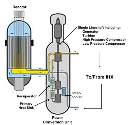
1
             Introduction

1.1 BACKGROUND
In 2000, the United States Department of Energy formed the Generation IV International Forum
(GIF) to advance nuclear energy in order to fulfill future energy needs. The GIF has categorized
the goals for future nuclear power into four areas, which are referred to throughout this report.

        −     Sustainability: Sustainability is the ability to meet the energy needs of the present
              generation while enhancing the ability to meet the energy needs of future generations
              indefinitely. Sustainability goals focus on waste management and resource
              utilization. The sustainability of GENIV systems also includes extending nuclear
              power into other energy areas, such as transportation, by using nuclear process heat
              to manufacture other energy products, such as hydrogen.

        −     Economic Competitiveness: Economic goals consider competitive costs and
              financial risks. Economic goals focus on reducing operating and capital costs
              through increased efficiency, design simplification, advances in fabrication and
              construction techniques, and possible standardization and modularization.

        −     Safety and Reliability: Safety and reliability goals include safe and reliable
              operation, improved accident management and mitigation, investment protection,
              and reduced off-site response. The focus for GENIV systems is on the use of
              inherent safety features and designs.

        −     Proliferation Resistance and Physical Protection: Proliferation resistance and
              physical protection goals consider methods for controlling and securing nuclear
              material and nuclear facilities against unintentional and intentional actions.

Through the efforts of ten countries, the GIF released a roadmap (cf. Ref. 2) outlining the
research and development necessary for six of the most promising future reactor designs. In the
upcoming years, each member state of the GIF will focus their efforts on the reactor design(s)
which best fulfills their future energy needs.

To outline their efforts, the U.S. has developed an implementation strategy for advancing the
Generation IV Roadmap (Ref. 13). This strategy consists of two priorities for the U.S.
Generation IV Program:

        −     Develop a Next Generation Nuclear Plant (NGNP) to achieve economically
              competitive energy products, including electricity and hydrogen, in the mid-term

Revision 0
                                                                                                 1-1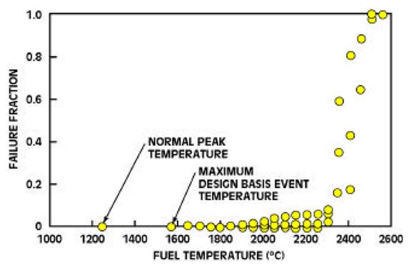
−    Develop a fast reactor to achieve significant advances in proliferation resistance and
             sustainability in the long term

This document focuses on the Next Generation Nuclear Plant (NGNP), which will be constructed
at the Idaho National Engineering and Environmental Laboratory (INEEL) by 2015. Although
still in the early conceptual phase, the NGNP is expected to be based on the Very High
Temperature Reactor (VHTR), one of the six proposed Generation IV concepts. The feasibility
of the VHTR has been demonstrated in past gas-cooled reactors (see Appendix B). The NGNP
will instead be a pilot facility for commercial deployment and licensing of future VHTR units.
The ultimate goals for commercial VHTR units are:

        −    Generate electric power at a cost of less than 1.5 cents/kW-hr
        −    Produce hydrogen at a cost of less than $1.50/gallon-gasoline equivalent
        −    Cost between $500-$1000/kW to construct

The VHTR is a suitable candidate for the NGNP due to the high efficiency electrical generation
and hydrogen production provided by its high operating temperatures. The VHTR is a helium-
cooled, graphite-moderated, thermal neutron spectrum reactor with a coolant outlet temperature
of 1000 °C or above. It will be a mid-size reactor with a thermal power of about 600 – 800
MWth. The final reactor power and core configuration will be designed to guarantee passive
decay heat removal during accidents in order to preclude radioactive release. The reactor will
utilize coated fuel particles in a once-through low-enriched uranium fuel cycle capable of very
high burnup. The motivation for basing the NGNP on the VHTR concept stems from the high
outlet temperatures. The high outlet temperature of the VHTR affords high efficiency (> 50%)
electrical generation and the use of nuclear power for potential process heat applications,
specifically carbon-free hydrogen production using nuclear heat.

1.2 PURPOSE
This report provides a technical description of the VHTR and a summary of the design and
development challenges facing the VHTR. Section 2 provides an overview of the general VHTR
design characteristics for the NGNP, planned to be built at the INEEL. Section 3 discusses the
technical issues which must be resolved for the NGNP and for commercial VHTRs. Next,
Section 4 contains the VHTR R&D timelines of the GIF and INEEL. The appendices provide
additional background and reference information. Appendix A lists the acronyms employed
throughout the report. Appendix B contains a brief survey of existing gas-cooled reactor
designs, and Appendix C briefly describes the other GENIV advanced reactor concepts chosen
by the GIF.

Revision 0
                                                                                                1-2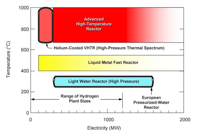
2
             The Very High Temperature Reactor

The term Very High Temperature Reactor (VHTR) loosely covers any reactor design with a
coolant outlet temperature of 1000 °C or above. The term typically refers to the next step in the
evolutionary development of high-temperature gas-cooled reactors (HTGRs). The Next
Generation Nuclear Plant (NGNP) refers specifically to the advanced reactor system which will
be constructed at the INEEL. Although a final decision has not yet been made, the NGNP is
expected to be based on the GENIV VHTR concept.

2.1 DESIGN BASIS

                      Figure 2.1-1. The NGNP Reactor Layout (Ref. 18)

Gas-cooled reactors (GCRs) have been investigated since the early days of nuclear power. The
early gas reactors were used commercially in the United Kingdom, but were overshadowed
elsewhere by LWRs and other designs. International interest in gas-cooled reactor technology
focused on development rather than deployment. This led to the construction of a number of
high temperature gas cooled reactor (HTGR) prototype and demonstration plants in Britain,
Germany, and the U.S. The focus of these plants was on evolutionary increases in coolant
temperature and plant efficiency. An overview of the development of HTGRs is provided in
Appendix B, “Brief Survey of Gas-Cooled Reactor Designs.”

Recently, interest in gas-cooled reactors has been renewed, and a number of HTGR designs have
been developed for near-term deployment (i.e., Generation III+ reactors). These include the
Pebble Bed Modular Reactor (PBMR) project, led by Eskom, and the Gas Turbine Modular
Helium Reactor (GT-MHR) project, led by General Atomics. The VHTR concept proposed by

Revision 0
                                                                                               2-1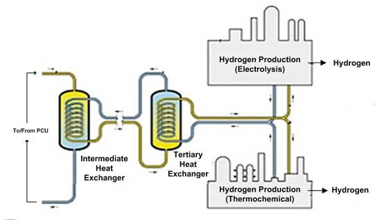
the GIF is an evolutionary extension beyond the near term HTGR designs. Consequently, a large
portion of the VHTR preliminary design is based directly on the existing near term designs.

Figure 2.1-1 depicts the reference VHTR conceptual design proposed by the INEEL for the
NGNP project. The basic features of the VHTR are similar to past HTGRs. Namely, the VHTR
is a helium-cooled, graphite-moderated reactor with a ceramic core and TRISO coated fuel
particles. The VHTR extends current HTGR technology to increase the coolant outlet
temperature to 1000 °C or above from past temperatures of about 850 °C. The increase in
temperature allows more efficient electrical generation and better thermal conditions for process
heat applications.

2.2 REACTOR
The VHTR is still in the early conceptual design phase, and a specific reactor design has not yet
been developed. As a result, the current VHTR core description is based largely on its
Generation III+ predecessors. The GT-MHR by General Atomics is the basis for the prismatic
VHTR; the PBMR by PBMR (Pty.), Ltd., is the basis for the pebble-bed VHTR. This section
will address the general structure of the two designs.

     Figure 2.2-1. The GT-MHR Reactor Core (Prismatic VHTR Reference Core) (Ref. 15)

The VHTR will use an annular core configuration. In a prismatic core (Figure 2.2-1), hexagonal
moderator and fuel blocks are arranged to form an inner graphite reflector (rings 1 – 5), a center
active fuel core (rings 6 – 8), and an outer replaceable graphite reflector (rings 9 – 10). The
active core is approximately 26 ft in height and consists of 102 fuel columns, each of which is a
stack of ten fuel blocks (1,020 fuel blocks total). In addition to the replaceable graphite
components, the prismatic core also includes a permanent side graphite reflector, vessel coolant
channels, and the core barrel. Helium enters the reactor core and flows up through the vessel
coolant channels before flowing downward through the integral coolant channels in the fuel
assemblies. This exposes the core barrel to the cooler inlet helium, rather than the hotter outlet
helium, thereby reducing the operating temperature of the barrel material.

Revision 0
                                                                                               2-2
The arrangement of the pebble bed VHTR core is similar to the prismatic core. The prismatic
fuel blocks in the active annular core region are replaced by mobile fuel pebbles, each
approximately the size of a tennis ball. These pebbles continuously circulate downward through
the core driven only by gravity. The pebbles are removed from the bottom of the core, and their
total burn-up is measured. Active pebbles are returned to the top of the core, while spent pebbles
are diverted to storage. Similar to the prismatic core, the inner and outer reflectors are
constructed from static moderator blocks. This simplifies the fuel handling process, but the
reflectors will require replacement at least once throughout the life cycle of the plant. The
pebble-bed core requires additional fuel handling systems, which increase costs, but can be
refueled while still online. In addition, the pebble-bed core requires additional analysis to predict
and verify the pebble dynamics. Both reactor designs use control rods for reactivity control and
shutdown, although the pebble-bed design also uses small absorber pebbles which are inserted
into the core for emergency shutdown.
As the VHTR design progresses, the fuel loading and core geometry will be optimized to provide
the coolant temperatures, inherent safety, and capability for high burnup that are the goals of
future Generation IV reactor systems. Examples of parameters which may be adjusted are the
dimensional parameters of the inner reflector, active core, and outer reflector and fuel parameters
such as the enrichment and packing fraction. Additional vessel cooling channels may also be
required in order to maintain the core barrel temperatures within acceptable material limits.
Despite differences between the fuel forms, the prismatic and pebble-bed VHTR reactors share
similar safety characteristics. The two designs use a mostly ceramic core which has a very high
thermal capacity and can withstand extremely high temperatures under accident conditions. This
is a major part of the inherent safety of the VHTR, as the core itself can dissipate a large amount
of decay heat before the fuel thermally degrades. On the other hand, the non-ceramic
components in the core such as the control rod sheaths and the core barrel typically suffer from
problems with high-temperatures, which are discussed further in Section 3.2. The low volume
fraction of fissile material within the fuel results in a low core power density. The moderator,
coolant, and fuel provide a strong overall negative temperature coefficient of reactivity. These
features give the VHTR reactor a large amount of thermal stability and reactivity control, which
provide inherent safety under accident conditions.
Due to the TRISO fuel (see Section 2.4), the pressure vessel is not required to be as leak-tight or
robust as traditional LWR vessels. In a departure from the near-term reactors used as a design
basis, the VHTR may use a modular pre-stressed cast iron pressure vessel (PCIV) to reduce
construction time and costs, pending further development and validation. Typical steel vessels
have size limitations for manufacture and transport, which can be overcome with a modular
approach. Cast iron materials may also have better high-temperature characteristics than typical
pressure vessel steels, although the high-temperature properties of candidate materials are mostly
unknown and require further research. The PCIV is a modular pressure vessel which will be
shipped to the site in pre-fabricated segments. The segments are assembled and pre-stressed on
site using axial and circumferential tendons and a bolted inner liner for leak tightness. This
pressure vessel design eliminates the possibility of a sudden catastrophic rupture, and the
superimposed compressive stresses limit the progression of large cracks.
Revision 0
2-32.3 POWER CYCLE
The VHTR will employ a direct Brayton cycle for the generation of electricity. For the
production of hydrogen, the VHTR will use an indirect cycle with an intermediate heat
exchanger (IHX).
First generation gas-cooled reactors included steam generators to accommodate an indirect
Rankine cycle for power generation. At the time, the closed Brayton cycle had not been
extensively developed, since the majority of gas turbine applications used an open cycle. For
nuclear applications, a closed cycle is required in order to retain the process gas for radiological
reasons. Recently, the closed Brayton cycle has undergone significant development in the
aerospace industry, which has demonstrated its high efficiency. In addition, the direct Brayton
cycle is much simpler than an indirect Rankine cycle, which leads to a number of safety and cost
benefits. Therefore, the VHTR will use a direct Brayton cycle in order to maximize the safety,
simplicity, and economy of its electrical generation.
For process heat applications like hydrogen production, the VHTR will use an indirect cycle with
an intermediate heat exchanger (IHX) to supply heat to the process application. An indirect
cycle isolates the process heat loop from the nuclear reactor, which allows the process heat
systems to be designed and built to non-nuclear standards. In addition, the thermal conditions
required for process heat applications can vary significantly from those within the reactor core.
These variations include temperature, pressure, and the frequency and/or magnitude of thermal
transients. Therefore, an indirect cycle is needed in order to provide a thermal interface between
the reactor and the chosen process heat application.
2.4 FUEL AND THE FUEL CYCLE
The VHTR will build upon the fuel developed for past HTGRs, the triple-isotropic coated fuel
particle (TRISO CFP). These particles are dispersed within a graphite matrix to form fuel
elements, the final form of which will be either prismatic or spherical (i.e., pebbles). The final
selection will be made pending completion of the conceptual designs for each. While this
arrangement results in a very flexible fuel design which can accommodate fast neutron
conditions, the fuel in the VHTR will be used in a once-through fuel cycle with a thermal
neutron spectrum.
Figure 2.4-1. TRISO (Triple Isotropic) Coated Fuel Particle (Ref. 11)
Revision 0
2-4TRISO fuel consists of a low-enriched uranium oxycarbide (about 15% UCO) fuel kernel
surrounded by three layers of pyrolytic carbon (PyC) which protect an additional ceramic layer
(see Figure 2.4-1). Fission products formed from uranium oxycarbide contain no free oxygen,
which could otherwise aggravate chemical degradation of the ceramic layer. The ceramic layer,
composed of silicon carbide (SiC), acts as a miniaturized pressure vessel that completely retains
all fission products. The layer begins to lose its integrity above approximately 1600 °C, which
represents the limiting fuel temperature under accident conditions. Two inner layers of PyC
protect the SiC layer against chemical attack from fission gases and against mechanical stress
due to irradiation swelling of the fuel kernel. An outer layer of PyC protects the SiC layer from
mechanical failure during handling and operation. These particles are mixed with graphite
powder and binders before being shaped and molded into the final fuel element.
The form of the final fuel assembly has taken two different forms in past designs. German
HTGRs, such as the AVR and THTR, used spherical fuel assemblies approximately 5 – 6 cm in
diameter. These have been traditionally referred to as “pebbles.” In HTGRs such as Peach
Bottom and FSV, U.S. designers used the “prismatic block” fuel assembly in which the CFPs are
formed into cylindrical fuel compacts before being inserted into hexagonal graphite fuel
elements. Modern pebble designs include the Chinese HTR-10 test reactor and the South
African PBMR Generation III+ reactor. Modern prismatic designs include the Japanese HTTR
test reactor and the General Atomics GT-MHR Generation III+ reactor.
Both fuel configurations have their advantages. The pebble designs typically include an
automated pneumatic fuel handling system which allows more flexible refueling options but at
greater expense. This greater expense may be offset by the potential for continuous online
refueling and decreased down time. The block design consists of integral coolant channels. In
the pebble design, the helium coolant flows between the interstices of the pebbles. The integral
coolant channels allow better core cooling, which in turn allows greater power density and total
core power with block fuel. The final choice of fuel element will be made following the point
designs of each.
The TRISO fuel design results in a very flexible fuel arrangement by essentially decoupling the
cooling geometry and neutronic optimization of the fuel. The fuel assembly shape, core
configuration, number of coolant channels, and packing fraction of fuel particles can all be
adjusted independently for different power levels, outlet temperatures, and fuel cycles. For
example, initial optimization studies have illustrated that greater packing fractions may extend
the overall cycle length due to additional self-shielding within the fuel (Ref. 15).
The fuel flexibility can also accommodate other fuel cycles, such as a closed fuel cycle with a
fast neutron spectrum. Over the next 50 years, the once-through open fuel cycle is considered
the most economical and proliferation-resistant choice for commercial reactors (Ref. 9). In
addition, the current SiC layer in TRISO fuel particles has increased susceptibility to fission
product release under the fast neutron conditions needed for a closed fuel cycle. The closed fuel
cycle also requires further development prior to commercialization and would delay other design
efforts. For these reasons, the VHTR is being designed for a once-through fuel cycle with a
thermal neutron spectrum.
Revision 0
2-52.5 BALANCE OF PLANT
2.5.1 Primary Heat Transfer Loop
Figure 2.5-1. NGNP Primary Heat Transfer Loop
The VHTR will have a primary heat transfer loop which will be used to generate electricity using
a closed Brayton cycle. Cool helium flows into the bottom of the core through the outer annulus
of the cross duct between the reactor and power conversion unit. The helium then flows upward
along the inner surface of the core barrel, through the vessel coolant channels within the core.
The coolant then is heated as it flows back down through the active core. The hot helium flows
out of the reactor through the inner pipe of the cross duct and into the power conversion unit.
After passing through the turbine, a portion of the helium will be diverted to the IHX to heat the
secondary loop, before returning back through the remainder of the power conversion unit.
The proposed configuration for the power conversion unit (PCU) is based on the configuration
used in the near-term GT-MHR design. In order to reduce onsite construction time and cost, the
power conversion unit (PCU) will be factory-fabricated in either modular units or as one
complete self-contained module. The PCU will contain all the necessary turbomachinery for
electrical generation. The turbine, generator, and compressors will be installed on a single
lineshaft in a vertical orientation. This provides a smaller footprint, which is advantageous since
both the reactor and the PCU will be situated below-grade, and also minimizes the length of the
cross duct between the reactor and PCU. The single lineshaft reduces the number of required
bearings and overall complexity of the turbomachinery, but introduces weight and alignment
issues. The near-term PBMR reactor offers an alternate configuration with the turbomachinery
on multiple horizontal shafts. The final configuration choice for the PCU requires a better
understanding of the advantages and disadvantages of each design.
Revision 0
2-62.5.2 Secondary Heat Transfer Loop
Figure 2.5-2. NGNP Secondary Heat Transfer Loop
The VHTR includes a secondary heat transfer loop to provide process heat for non-electrical
energy products, of which hydrogen is the primary candidate. The NGNP will also have a
tertiary heat transfer loop, as shown in Figure 2.5-2. This simple loop adds an additional heat
exchanger to further isolate the reactor and hydrogen loops and mitigate contamination and
thermal transients. The NGNP will evaluate the cost-benefits of this additional loop, which may
be eliminated in future VHTR generations (or the final NGNP design) for simplification and
cost-reductions.
Helium, or another suitable heat transfer medium such as molten salt, enters the IHX where it is
heated by helium from the primary loop. Due to the low thermal transfer of helium gas, the IHX
requires a very large surface area for heat transfer. This would require an extremely large and
uneconomical tube and shell heat exchanger. Instead, the VHTR will use a compact plate and fin
or a “printed circuit” heat exchanger, pending qualification of a viable design.
The remainder of the secondary loop will depend on the specific process heat application.
Although the long-term vision for the VHTR involves many potential process heat applications,
the NGNP will demonstrate nuclear hydrogen production. The NGNP will include two hydrogen
production loops in order to investigate and develop different hydrogen production systems.
Hydrogen production using nuclear process heat is discussed in Section 2.6. Other potential
process heat applications are discussed in Section 2.7.
2.5.3 Reactor Cavity Cooling System
A reactor cavity cooling system (RCCS) is needed in order to remove decay heat from the core
during accident events. A design goal of the VHTR is to use its intrinsic safety features to make
an active RCCS unnecessary. A passive heat removal system will be used to limit core and fuel
temperatures in order to prevent structural damage or radioactive release. Passive heat removal
methods do not require operator intervention or external power and therefore are more reliable.
Figure 2.5-3 illustrates the passive RCCS of the near-term GT-MHR. The primary decay heat
Revision 0
2-7removal methods are radiation and conduction to the reactor cavity structure and to the earth.
The RCCS contains cooling panels and an intake/exhaust duct to allow naturally convecting air
to remove additional heat. The VHTR will employ a similar passive system, if such a system
can be shown to maintain vessel and fuel temperatures within acceptable limits.
Figure 2.5-3. GT-MHR Passive RCCS and Peak Accident Core Temperatures (Ref. 19)
One issue in finalizing the VHTR design is to find the optimal balance between economics and
safety. That is, the cost-benefits of higher power densities and a smaller reactor size must be
balanced with the RCCS capability and vessel temperature capabilities to maintain post-accident
temperatures below acceptable limits. Therefore, the amount of decay heat which the RCCS is
capable of removing becomes a key element in the design. Similar to the vessel material
temperature limit (see Section 3.2.3), improving the capability of the RCCS will improve the
cost-safety envelope of the VHTR.
2.5.4 Other BOP Equipment
Helium gas was chosen as the coolant for the VHTR because of its chemical and radiological
inertness. The helium coolant will not corrode components or equipment. However, the high
temperatures of the VHTR aggravate chemical attack from impurities in the helium. This issue
is discussed further in Section 3.2.2, below. To prevent this, the VHTR will require systems to
monitor and purify the helium coolant. These systems will most likely not be safety-related, but
will still be important in preventing long-term structural damage and failure.
Past HTGR units, specifically Fort St. Vrain, used traditional bearings in the turbomachinery. As
a result, FSV experienced extensive downtime resulting from contamination problems due to
lubrication ingress. The VHTR will use magnetic bearings, a relatively recent development, in
order to prevent this. However, magnetic bearings are active components which require power
to create the electromagnetic field. Therefore, the VHTR will require additional catcher
bearings, which must be designed for potential drops and coast-downs.
Revision 0
2-82.6 HYDROGEN PRODUCTION USING NUCLEAR PROCESS HEAT
The major impetus in the U.S. for the VHTR is its potential for hydrogen production. Hydrogen
represents a key element in the future U.S. energy policy for reduced carbon emissions and
increased energy independence. The long-term vision of the GIF (Ref. 2) is to allow a 600
MWth VHTR dedicated to hydrogen production to produce over 2 million cubic meters of
hydrogen per day (details such as assumed efficiency, etc. were not provided). This is the energy
equivalent of over 160,000 gallons of gasoline per day.
Three categories of methods are typically considered for generating hydrogen. These are steam
reformation of methane, electrolysis, and thermochemical cycles. Of these, the U.S. will
investigate conventional electrolysis, high-temperature steam electrolysis, and a variety of
thermochemical cycles for use in the NGNP hydrogen production plant, due to their expected
roles in the future hydrogen economy.
2.6.1 Steam Reformation
Steam reforming of methane is the current process of choice for large-scale hydrogen production,
and may have a role as an early centralized production method. However, methane is already a
high quality fuel, and steam reformation is a mature process which does not require further
development. Furthermore, the process results in carbon emissions and diverts natural gas from
residential use. Therefore, steam reformation is unable to fulfill the future U.S. energy needs
since it is not sustainable in the long-term. This method may fulfill large-scale production needs
during the early periods of the hydrogen economy, but will not be considered for the NGNP
hydrogen production plant since it will be phased out in the long-term and is already well-
developed.
2.6.2 Electrolysis
Conventional water electrolysis is a well-established process and is the traditional benchmark for
other hydrogen production processes. The overall production process has low efficiency due to
the typical inefficiencies absorbed with electrical generation. However, electrical energy is
easily transported. This makes conventional electrolysis ideal for distributed hydrogen
production, which will be most profitable in the initial stages of the hydrogen economy. Before
significant demand for hydrogen exists, distributed production will avoid hydrogen
transportation costs, which can be significant with currently available storage technology (Ref.
16). Therefore, conventional electrolysis will play a key role in enabling early distributed
production in the future hydrogen economy.
Steam electrolysis uses thermal energy to produce high-temperature steam prior to electrolysis.
This displaces a portion of the required electrical energy with thermal energy, which improves
the overall efficiency. This process requires a separate high temperature heat source which is
disadvantageous for distributed production. However, steam electrolysis will play an important
role as an early, efficient, and emission-free (when coupled with nuclear power) hydrogen
production method. Both conventional electrolysis and high-temperature steam electrolysis will
employ modular scaling to allow increased production capacity. In addition, each has potential
Revision 0
2-9applications in peak-shaving by utilizing electricity from the grid during off-peak times. Both
methods are undergoing further development to increase their performance.
Both conventional electrolysis and high-temperature steam electrolysis are being considered for
application in the NGNP, since they will be key elements of the future hydrogen economy and
can benefit from the VHTR. The cost of electrolysis is highly dependent on the cost of
electricity. In this area, the VHTR will provide modest benefits to both conventional and steam
electrolysis since its high-temperatures and direct Brayton cycle result in highly efficient
(> 50%), and therefore low-cost, electrical generation. The VHTR can also be the source of
high-temperature process heat for steam electrolysis, providing emission-free thermal energy
which would otherwise have come from fossil fuels.
2.6.3 Thermochemical Cycles
The direct pyrolysis of water requires temperatures greater than 4000 °C. Thermochemical
cycles are able to decompose water into hydrogen and oxygen at significantly lower
temperatures. This is achieved by using chemical reactions to initially dissociate water and then
splitting the intermediate compounds with either heat or electricity. Thermochemical cycles
have been widely investigated in the past, and a large number of different cycles exist today.
However, most require significant development for commercial application. These processes are
expected to provide centralized, large-scale, efficient, and emission-free hydrogen production
when coupled with high-temperature nuclear reactors.
The NGNP program is currently investigating a number of thermochemical cycles which belong
to two general families. The highest priority is given to the sulfur-based family consisting of the
sulfur-iodine cycle, the hybrid sulfur cycle, and the sulfur-bromine cycle. Lower priority is
given to the calcium-bromine family of cycles, which will not be discussed here.
Figure 2.6-1. Sulfur-Based Thermochemical Cycles (Ref. 14)
The sulfur-based cycles are illustrated in Figure 2.6-1. The sulfur-iodine cycle is generally
presented as the ideal long-term goal for hydrogen production since it is the most efficient
Revision 0
2-10production method. It is an all-liquids-and-gases cycle with three thermochemical steps. The
sulfur-iodine cycle is the most efficient of the sulfur-based cycles and has been demonstrated at
the laboratory-scale at JAERI. However, the separation techniques employed in the process
require further development for commercial scale-up and system design. The hybrid sulfur cycle
is also an all-liquid-and-gases cycle, but with one thermochemical step and one electrolytic step.
With only two steps using only two sulfur compounds, it is the simplest thermochemical process.
The last sulfur-based cycle, the sulfur-bromine cycle, is being considered as a contingency since
this process is more complicated and less efficient than the hybrid sulfur cycle.
2.7 OTHER PROCESS HEAT APPLICATIONS
The impetus for higher operating temperatures consists of higher thermal efficiency and the
eventual expansion of nuclear energy beyond electrical generation. The latter motive manifests
itself in the desire to expand the potential for nuclear process heat (NPH) in industrial
applications, beyond hydrogen production in the near-term. Figure 2.7-1 shows the required
temperatures for industrial applications and the coolant temperatures of various reactor designs.
Note that the upper limit of 1500 °C is a very optimistic goal for the VHTR which will not be
realized until later generations. NPH applications range from desalination and district heating on
the low-end of the temperature scale to iron and glass manufacture on the high-end. Research
conducted during the Nuclear Steelmaking System (NSS) Project in Japan during the 1970s
showed that most of the high temperature processes could be modified to use temperatures
around 1000 °C. One of the long-term goals of the VHTR includes possible deployment at
industrial park sites. This would allow the VHTR to replace fossil fuels in the long-term as a
source of high-temperature process heat for energy-intensive industrial processes in order to
reduce carbon emissions.
Figure 2.7-1. Nuclear Process Heat Applications and Required Temperatures (Ref. 4)
Revision 0
2-112.8 SAFETY AND PROLIFERATION RESISTANCE
Past and near-term HTGRs have illustrated the high level of safety inherent to gas-cooled
reactors. The graphitic core structure, helium coolant, and coated fuel particles allow the VHTR
to withstand accident temperatures without structural damage or fission product release. This
provides a significant amount of inherent safety which eliminates the need for active, and
expensive, safety systems such as those in current LWRs. Also, HTGRs have inherently better
proliferation resistance compared to current LWRs due to their dilute fuel form and difficulty in
reprocessing. This section discusses the safety and proliferation resistance inherent to all gas-
cooled reactor designs, since the evolutionary changes to the VHTR do not provide any
additional inherent safety or proliferation resistance. To the contrary, the higher temperatures
and hydrogen production plant present unique safety challenges which must be overcome to
maintain the inherent safety of HTGRs; these are discussed further in Section 3.
The graphite core of HTGRs has a high thermal conductivity, which aids in preventing hotspots
from forming within the core. The high thermal capacity of graphite combined with the low core
power provides a relatively long delay in the thermal response during loss of coolant accidents or
reactivity insertions. The maximum fuel temperature is not expected to occur for several days
following a loss of coolant (Ref. 2), providing significant time for operators to take action.
Figure 2.8-1 shows the peak core temperatures during a loss of coolant computer analysis for
different VHTR core layouts. In each case, the peak temperatures are not reached for
approximately 2 – 3 days. In addition, the helium coolant, graphite moderator, and TRISO fuel
combine to give the core a strong negative temperature coefficient of reactivity. This provides
power and temperature attenuation during accidents, since the fission reaction rate (i.e., the rate
of heat generation) slows as the core temperature increases.
Figure 2.8-1. VHTR Peak Temperatures During Accident (Ref. 23)
Initial safety demonstration tests are being performed at the HTTR in Japan (Ref. 12). Reactivity
insertion and partial coolant flow reduction tests have already been completed, and they confirm
the core safety aspects mentioned above. During the reactivity insertion, the reactor power
slowly increased. Once insertion was completed, the increasing fuel and moderator temperatures
immediately began to slow the fission rate and reduce reactor power. During this test, the reactor
Revision 0
2-12power peaked but was attenuated within an hour to a small net increase. The test illustrated that
the reactor power during a reactivity insertion event can be regulated solely by the negative
reactivity feedback of the core, without requiring the use of active reactor power control systems.
A similar effect was seen when test personnel reduced coolant flow. The initial reduction in
coolant flow reduces the amount of heat transfer from the core. The resultant increase in core
temperature causes a reduction in the rate of heat generation due to negative reactivity feedback.
Thus, both the reactivity insertion and the partial coolant flow reduction events illustrate the
intrinsic safety and stability of HTGR reactors.
The self-attenuating reactivity coefficient of HTGRs results in eventual power stabilization
during accidents and transients. Therefore, the major goal of accident mitigation and prevention
becomes the limitation of maximum core and fuel temperatures. The ceramic and non-ceramic
core components will be designed to have sufficient high-temperature capabilities to preclude
structural damage. Thus, the limiting case becomes the degradation of the fuel coatings at high
temperatures and subsequent release of fission products. This is the motivation for limiting the
maximum fuel temperature during accidents below the degradation temperature of the fuel (i.e.,
1600 °C for SiC TRISO fuel).
The TRISO coated fuel particles represent another intrinsic safety feature of HTGRs. As
mentioned before, each fuel particle is essentially its own pressure vessel able to retain fission
products. This results in very little radioactive release and plate-out during operation, as has
been shown by past HTGR prototype and demonstration plants. For example, personnel
exposure at FSV was exceptionally low, approximately 1 person-rem/year (Ref. 8, p. 59). In
addition, the carbide pressure vessel retains fission products even after the operational lifetime of
the fuel is over. Therefore, coated fuel particles represent an ideal final waste form, if they can
be separated from the large amounts of extraneous low-level graphite waste. As a result, TRISO
fuel may require less overpacking than traditional LWR fuel, reducing the total amount of
repository space required.
Another intrinsic safety feature of HTGRs is the helium coolant. Helium is chemically and
neutronically inert. This precludes safety complications which can arise due to irradiation of the
coolant or corrosion of component materials. Contrary to water-cooled reactors, helium does not
undergo a phase change at or above reactor operating temperatures. This simplifies the
mechanical design and operation of the reactor, thereby improving the safety. On the other hand,
helium does not have the same biological shielding effect as water. This results in higher
radiation exposure in and around the core than traditional LWRs.
Gas-cooled reactors are able to retain fission products effectively and are designed to prevent
radioactive release without operator intervention or active safety systems. Therefore, no external
accident management should have to be undertaken outside the plant fence. That is, HTGRs do
not require any offsite emergency response. Also, HTGRs do not require as leak-tight a
containment building as LWRs, which could reduce capital costs. These advantages have
significant economic benefits, but raise a number of safety concerns from opponents of nuclear
power who are hesitant to rely on the inherent safety of advanced reactors. Ultimately, these
features may allow the VHTR to be built at industrial sites in areas with dense population, in
order to support process heat applications and reduce carbon emissions.
Revision 0
2-13HTGRs also have intrinsic design features for proliferation resistance. The VHTR has a
relatively low power density and overall power output compared to contemporary monolithic
water-cooled reactors. These features result in initially low fissile inventories and a highly dilute
fuel form. In addition, TRISO fuel is difficult to reprocess. Each coated fuel particle has a
diameter of approximately 650 to 850 microns. A full fuel load for the VHTR will contain
approximately 10 billion coated particles which must be separated from the graphite pebbles or
blocks in which they are dispersed. Reprocessing is further complicated since the protective
pyrolytic carbon and silicon carbide layers must also be removed in order to gain access to the
fissile material. Although these features do not completely prohibit reprocessing, they greatly
complicate the process when compared to traditional LWR fuel reprocessing.
Revision 0
2-143
Technical Challenges
The technology of the VHTR is based largely on former HTGR plants, which provide an
extensive knowledge base. The VHTR will also benefit from the similarities of other advanced
HTGR designs. Two gas-cooled reactor designs are being developed for near-term deployment
in the 2010 time frame, the Gas Turbine Modular Helium Reactor (GT-MHR) by General
Atomics and the Pebble Bed Modular Reactor (PBMR) by Eskom. These Generation III+
reactors have coolant outlet temperatures around 850 – 950 °C, and their development and
operation will help to resolve many of the issues facing the VHTR. Nevertheless, the VHTR will
require R&D to increase the operating temperature to 1000 °C and beyond, to develop the
interface and systems for nuclear process heat applications, and to qualify the system for
commercial licensing.
3.1 FUEL
TRISO coated fuel particles have been used extensively in past HTGR prototype and
demonstration reactors and already have a well-developed knowledge base. Consequently, the
majority of fuel development work is focused on the modeling and testing required to
demonstrate safe operation and to support fuel licensing for commercial operation. Although not
required in the near-term, several developmental activities are envisioned for increasing the
safety, economics, and sustainability of TRISO fuel in the long-term.
The main goal of fuel development work for the NGNP is to develop an understanding of the
fabrication process, fuel properties, irradiation performance, and the release and transport of
fission products. Research in the manufacture of TRISO fuel will focus on further developments
in the fabrication process and quality control methods. Quality control is an important issue due
to the large number of coated fuel particles necessary for the VHTR fuel assemblies. A full fuel
load will contain on the order of 10 billion coated particles, each approximately 650 to 850
microns in diameter. Activities are also necessary to identify temperature and irradiation effects
on fuel properties and to model possible failure mechanisms. Also, fission product transport and
release due to particle failure must be understood and modeled in order to support licensing.
These tasks are aimed at developing and validating the computer codes and models required for
design and licensing activities, in order to demonstrate a thorough understanding of the in-
service behavior of the fuel.
The current HTGR fuel, SiC TRISO coated fuel particles, is acceptable for use in the NGNP,
even with its higher coolant temperature. Preliminary analyses for the NGNP have shown that
the VHTR target outlet temperature (1000 °C) can be achieved through thermal-hydraulic
optimization of the core, without increasing the maximum fuel temperature during operation and
accident conditions (Ref. 14). Furthermore, the traditional 1600 °C design limit for SiC fuel
provides significant margin since noticeable failure does not occur until approximately 1900 –
Revision 0
3-12000 °C (Figure 3.1-1). However, the economics, safety, and sustainability of the TRISO fuel
can be improved in the long-term.
Figure 3.1-1. SiC Coated Fuel Particle Temperature Capability (Ref. 19)
SiC fuel does not begin to degrade until higher temperatures, but 1600 °C is traditionally used as
the limiting fuel temperature during accidents. Preliminary studies show that zirconium carbide
(ZrC) may provide a greater temperature margin than SiC, raising the fuel design temperature to
approximately 1800 °C. This would provide increased safety margins and perhaps even allow
higher temperatures, which would improve the overall efficiency of the VHTR. ZrC may also be
a viable coating for use in gas-cooled reactors with a closed fuel cycle, such as the Gas-Cooled
Fast Reactor. However, ZrC requires significantly more fabrication development and validation
testing than current SiC fuel.
An automated fabrication process may ultimately be developed to lower costs and improve the
quality of the fuel. Developmental studies are also aimed at extending the achievable fuel
burnup, which would improve the sustainability and operating costs of the VHTR. Ultimately
the VHTR will provide a maximum fuel burnup of 150 – 200 GWd/MTHM (Ref. 2), which is
approximately 3 – 4 times that of current LWR fuel (Ref. 21). Research is also needed for the
back-end of the fuel cycle, namely the disposal of spent VHTR fuel. The fuel particles
themselves, the high-level waste, represent an ideal waste form due to the SiC “pressure vessel”
which retains all fission products. This may reduce the amount of required shielding and the
overall required repository space. However, these particles are dispersed throughout a much
larger volume of low-level graphite waste. This requires the development of separation and
disposal processes for the graphite low-level waste, which may prove to be too complex or costly
to be effective. Incineration may present an effective disposal method for the graphite, but the
full ramifications have not yet been investigated.
3.2 MATERIALS
The bulk of research for the VHTR is in the area of material development and qualification for
the reactor, fuel, and components. Near-term designs have contributed significantly to the
development and analysis of gas-cooled reactors, and their operation will be a significant
Revision 0
3-2contributor to the state of the art. However, the VHTR will require materials to operate under
higher temperatures and neutron fluxes than have been experienced in prior nuclear service,
including near-term designs. This issue is further complicated by the fact that the VHTR design
is not completely finalized; therefore, the exact material requirements may change somewhat as
the design progresses. Instead, development of a material property database for candidate
materials will be initiated early in the project, in order to support an iterative process of refining
component and material requirements. This section first describes the properties database which
will be established to support VHTR design activities. Next, a brief description is given of the
differences in the VHTR service conditions and their material effects. Finally, specific
components of the VHTR are discussed for which materials issues still need to be resolved.
3.2.1 Material Properties Database
The higher temperatures and neutron fluxes of the VHTR will result in a rather complex
interaction between radiation damage, diffusion phenomena, and direct chemical reactions. The
resulting changes to the microstructure of materials affect a number of material properties, which
are listed below. Part of the material research for the VHTR will focus on developing a better
understanding of the relationship between microstructure changes and material properties
through testing and modeling. The complexity of the issue will ultimately require significant
empirical testing. The results of this testing will be used to begin development of a design
database for the material properties and high-temperature behavior under the expected VHTR
service conditions, in order to support licensing.
The VHTR service conditions are beyond the temperatures and irradiation levels of
contemporary LWRs. A number of high-temperature candidate materials have been developed
over the past 60 years for gas turbines in the aerospace industry and for past HTGR
demonstration and near-term reactors. However, a significant amount of further effort is
required to validate and qualify these materials for commercial nuclear service. After surveying
the existing data for candidate materials, researchers will perform additional testing to quantify
necessary material properties for the most promising materials. For each selected material, the
design database must contain sufficient data to demonstrate that the material will perform its
design function over the relevant temperatures, irradiation conditions, and component lifetime.
Examples of material properties which must be documented are:
− Thermal Expansion − Ductility
− Irradiation Growth − Toughness
− Grain Boundary Growth − Creep Rupture Strength
− Void Swelling − Fatigue Cracking Resistance
− Thermal Creep − Helium Embrittlement
− Irradiation Creep − Corrosion Resistance
− Irradiation Embrittlement − Oxidation Resistance
− Stress Relaxation − Contamination Effects
− Strength
Revision 0
3-3You can also read