TOWN CENTER COMMUNITY PARK WEST FIELD 1 IMPROVEMENTS CIP 2022-40
←
→
Page content transcription
If your browser does not render page correctly, please read the page content below
Department of Development Services

TOWN CENTER COMMUNITY PARK WEST
      FIELD 1 IMPROVEMENTS
            CIP 2022-40
              Design-Build Contract

         RFP Issued| September 27, 2021

Pre-Proposal Meeting | October 12, 2021 at 10:00am

   Proposals Due | October 28, 2021 at 5:00pm

           Estimated Budget | $800,000

                                                     City of Santee
                          10601 Magnolia Avenue • Santee, CA 92071
                                                    (619) 258-4100
                                          www.CityofSanteeCA.gov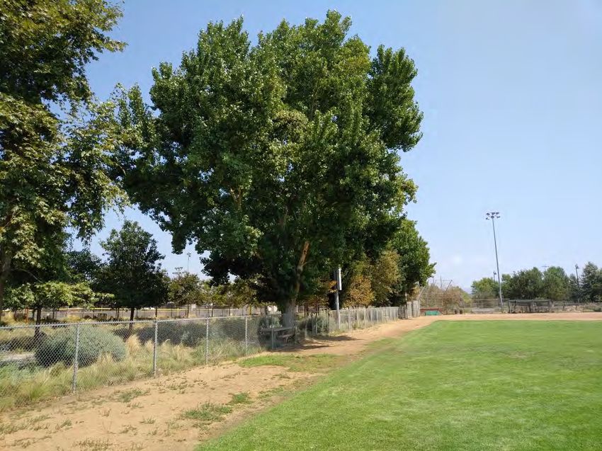
CITY OF SANTEE
                         REQUEST FOR PROPOSALS
           TOWN CENTER COMMUNITY PARK WEST, FIELD 1 IMPROVEMENTS

                                     TABLE OF CONTENTS
1   INTRODUCTION ....................................................................................................... 1
2   RFP INQUIRIES ........................................................................................................ 1
3   PROJECT SCHEDULE ............................................................................................. 2
4   PRE-PROPOSAL MEETING..................................................................................... 2
5   SCOPE OF SERVICES ............................................................................................. 2
     5.2 Project Design ................................................................................................... 11
    5.3 Project Management ......................................................................................... 12
    5.4 Use of Project Site ............................................................................................ 12
    5.5 Proof of Performance ........................................................................................ 13
    5.6 Project Submittals ............................................................................................. 13
    5.7 Contract Closeout Submittals............................................................................ 14
    5.8 Warranty ........................................................................................................... 14
6   PROPOSAL FORMAT AND CONTENT ................................................................. 15
    6.1 Transmittal Letter / Executive Summary ........................................................... 15
    6.2 Experience, Technical Competence & References ........................................... 15
    6.3 Staffing Plan and Key Personnel ...................................................................... 16
    6.4 Licensing and Professional Certifications.......................................................... 16
    6.5 Proposed Method to Accomplish the Work ....................................................... 16
    6.6 Pricing / Fee to Perform Service ....................................................................... 17
    6.7 Previous City experience and Conflict of Interest.............................................. 18
    6.8 Appendices or Exhibits...................................................................................... 18
7   PROPOSAL SUBMITTAL REQUIREMENTS ......................................................... 18
    7.1 Submittal Location ............................................................................................ 18
    7.2 Bid Guarantee ................................................................................................... 19
8   EVALUATION CRITERIA AND SELECTION PROCESS ....................................... 19
9   GENERAL REQUIREMENTS ................................................................................. 20
    9.1 Public Record.................................................................................................... 20
    9.2 Right to Cancel ................................................................................................. 20
    9.3 Additional Information ....................................................................................... 20
    9.4 Conflict of Interest ............................................................................................. 20
    9.5 Insurance Requirements ................................................................................... 20
    9.6 Bond Requirements .......................................................................................... 21
    9.7 Workers’ Compensation .................................................................................... 21
    9.8 Licenses and Permits ........................................................................................ 21
                                                           ii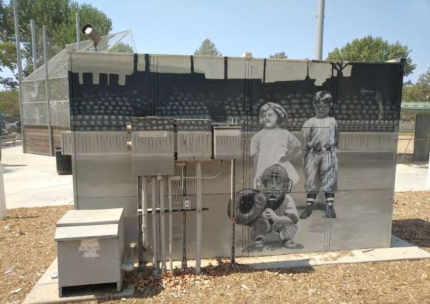
9.9 Commitment to Equal Opportunity .................................................................... 22
      9.10      Non-Collusion Affidavit ................................................................................. 22
      9.11      Time for Completion ..................................................................................... 22
      9.12      Liquidated Damages .................................................................................... 22
      9.13      Ineligible Contractors ................................................................................... 22
      9.14      Contractor Registration ................................................................................ 22
      9.15      Prevailing Wages: ........................................................................................ 23
      9.16      Employment of Apprentices ......................................................................... 23
EXHIBIT ‘A’ – SITE PLAN ............................................................................................. 24
EXHIBIT ‘B’ – SOFTBALL FIELD LAYOUT DIMENSIONS .......................................... 25
EXHIBIT ‘C’ – SPORTS LIGHTING EQUIPMENT......................................................... 26
EXHIBIT ‘D’ – ELECTRICAL EQUIPMENT ................................................................... 27
EXHIBIT ‘E’ – SCOREBOARD POWER........................................................................ 28
EXHIBIT ‘F’ – IRRIGATION CONTROLLER EQUIPMENT ........................................... 29
EXHIBIT ‘G’ – EXISTING DUGOUT AND SIDELINE NETTING ................................... 30
EXHIBIT ‘H’ - TREE REMOVAL .................................................................................... 31
EXHIBIT ‘I’ - BID BOND ................................................................................................ 32
EXHIBIT ‘J’ - NON-COLLUSION AFFIDAVIT ............................................................... 34
EXHIBIT ‘K’ - PERFORMANCE BOND ......................................................................... 36
EXHIBIT ‘L’ - MATERIAL AND LABOR BOND ............................................................ 40
EXHIBIT ‘M’ - WORKERS’ COMPENSATION CERTIFICATE ...................................... 44
EXHIBIT ‘N’ - WORKERS’ COMPENSATION CERTIFICATE FOR SOLE
PROPRIETORS ............................................................................................................. 46
ATTACHMENT ‘A’ - SAMPLE AGREEMENT
ATTACHMENT ‘B’ – GENERAL CONDITIONS
ATTACHMENT ‘C’ – APPROVED MATERIALS LIST
ATTACHMENT ‘D’ – AS BUILT DRAWINGS

                                                           iii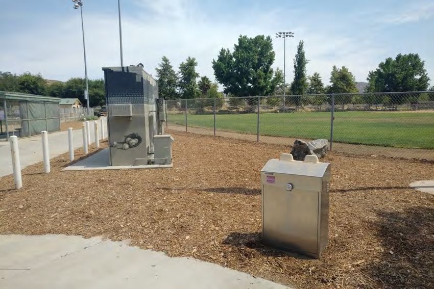
1   INTRODUCTION
    The City of Santee, hereinafter referred to as “City”, is seeking proposals from qualified firms,
    contractors or consultants, hereinafter referred to interchangeably, to modify the existing
    Field 1 at the Town Center Community Park West site located at 9409 Cuyamaca Street by
    removing the existing Field 1 baseball field improvements and installing two smaller softball
    fields in order to meet the demand of the City’s softball field user pending funds available.

    This Request for Proposals (RFP) describes the Project, the required scope of services, the
    selection process, and the minimum information that must be included in the proposal.
    Failure to submit information in accordance with the RFP requirements and procedures may
    be cause for disqualification.

    Based on this RFP, the City intends to select one firm for agreement negotiations. If the City
    is unable to reach an agreement with the selected firm, then the City has the option to
    negotiate with another. Award of the contract, if any, will be to the firm whose professional
    qualifications, experience, and proposed work plan demonstrates that it will competently
    satisfy the requirements described in this RFP within the City’s budget. Price will be a primary
    factor, but will not be the sole consideration for award. This RFP does not commit the City
    to award any contract, defray any costs incurred in the preparation of a proposal pursuant to
    this RFP, or in any resulting negotiations, or to procure contracts for work.

    The successful firm will be expected to execute the City’s standard, template contract
    agreement and will be required to meet specific insurance requirements and provide proof of
    Professional Liability insurance as specified in Attachment ‘B’ – General Conditions. All
    designers, contractors, subcontractors, journeymen and apprentices working on the Project
    must be licensed and registered with the State of California, as required. Additionally, the
    selected firm and any subcontractors must have, or will be required to obtain, a business
    license to work in the City of Santee.

    The City’s estimated budget for the Project is $800,000.00

    Any changes to this RFP are invalid, unless specifically modified by the City and issued as a
    separate addendum document. Should there be any question as to changes to the content
    of this document, the City’s copy shall prevail. All addenda and notices related to this
    solicitation will be posted by the City on the City’s website at www.cityofsanteeca.gov under
    the “Bid Opportunities” of the main page. In the event this RFP is obtained through any
    means other than the City’s website, the City will not be responsible for the completeness,
    accuracy or timeliness of the RFP document.

2   RFP INQUIRIES
    All questions concerning this RFP must be submitted in writing and received no later than
    5:00 p.m. on October 22, 2021. Questions must be directed to:
           Steven Miller, Senior Civil Engineer
           City of Santee
           10601 Magnolia Avenue
           Santee, California 92071
           (619) 258-4100 ext. 176
           Email: smiller@cityofsanteeca.gov

                                               1
Information relative to this RFP obtained from other sources may not be accurate and will not
     be considered binding. Contact with City personnel other than the staff person listed above
     regarding this RFP may be grounds for elimination from the selection process.

3    PROJECT SCHEDULE
     Following is the City's tentative schedule for selection of a qualified firm and expected
     completion of the Project:

        1. Request for Proposals Issued                           September 27, 2021
        2. Pre-Proposal Meeting                                   October 12, 2021 at 10:00am
        3. Final Date Questions Due for Consideration             October 22, 2021 at 5:00pm
        4. Proposals Due                                          October 28, 2021 at 5:00pm
        5. Staff Review of Proposals                              November 1 - 5, 2021
        6. Interviews with Selected Firms (optional)              November 8 - 12, 2021
        7. Anticipated Award of Contract                          December 8, 2021
        8. Notice to Proceed Issued                               January 3, 2022
        9. Preliminary Design Completion                          March 3, 2022
        10. Project to be Fully Complete                          July 15, 2022

4    PRE-PROPOSAL MEETING
     A pre-proposal meeting and walk-thru will be held on October 12, 2021 at 10:00am to provide
     an opportunity for firms to tour the project site, examine current site conditions and obtain
     more information on the Project. Proposers should attend this meeting to visit the site in
     order to check and verify existing conditions prior to submitting a proposal.

     This meeting will be held at Town Center Community Park West, Field 1, 9409 Cuyamaca
     Street, Santee, CA 92071. Allow approximately one (1) hour and bring a complete RFP
     packet for reference. Due to COVID-19, attendees will be required to practice social
     distancing and wear face masks during the pre-proposal meeting.

     Proposers will be responsible for verifying and inspecting the Project site prior to submitting
     a proposal and will assume full responsibility for having familiarized themselves with the
     locality and local conditions that may in any manner affect the work to be done. Submission
     of a proposal shall be prima facie evidence that the Proposer has made such examination
     and is satisfied as to the conditions to be encountered in performing the work and as to the
     requirements of this contract.

     The City of Santee complies with the Americans with Disabilities Act. If you require
     reasonable accommodations for the pre-proposal meeting, please contact the Office of the
     Director of Development Services at (619) 258-4100 extension 168, at least 48 hours prior to
     the meeting.

5    SCOPE OF SERVICES

5.1.1 General

                                               2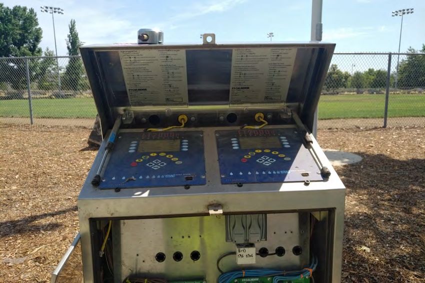
The successful firm shall provide all necessary design services, project management, and
     construction services required to remove the existing Field 1 baseball field and install 2 girls
     softball fields within the existing Field fence line area. Both fields shall be constructed as
     combination 10U/14U softball fields with a 175’ outfield as shown on the site plan.

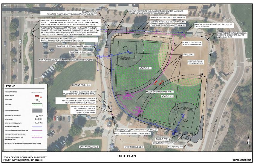
     The site plan (Exhibit ‘A’) is the preliminary layout identifying the desired field orientations,
     concrete walkways and location of major site furnishings for the site.

     All materials used on the project shall be selected from the City’s Approved Materials List
     (Attachment C) or approved equal. The City uses Calsense irrigation controllers and Musco
     Sports Lighting Controls for the existing irrigation and sports lighting systems. No alternate
     product will be permitted as they integrate into existing communication and control systems.

5.1.2 Demolition, Clearing and Grubbing

     The following items shall be removed and legally disposed of:

        •   Chain link fencing, chain link gates, poles, chain link fabric, fence rails, foundations,
            fittings and hardware.
        •   Backstop poles, chain link fabric, rails, fittings, hardware. Poles shall be cut flush with
            concrete and filled with concrete with smooth finish.
        •   Dugout Poles, chain link fabric, rails, fittings, hardware, gates, roofing, benches.
            Poles shall be cut flush with existing concrete and filled with concrete with smooth
            finish.
        •   Existing irrigation lateral piping, fittings, rotors and spray bodies. Remote control
            valves shall be removed and capped on pressure side of valve. Existing valve wires
            shall remain in place.
        •   Existing grass turf shall be removed. In areas to receive infield mix for new field
            layout, 4-inches of top soil shall be removed and disposed of to allow for infield mix.
        •   Existing Hunter Irrigation controller, scoreboard controller, load center panel, 120V
            receptacle, transformer, their supporting hardware and underlying concrete support
            flatwork.
        •   Any portion of the existing Calsense irrigation controller shown to be upgraded that
            are no longer required.

     All metal, wood, copper wire and concrete shall be recycled at applicable recycling facilities
     to prevent unnecessary material from entering landfills.

5.1.3 Site Work

     Site Soils:
     Existing site soils are composed of silty sand. During prior existing excavation at this this
     site, ground water was encountered at a depth of 5’ due to the proximity of the San Diego
     River. The contractor shall assume that steel caissons will be required to be used to support
     foundation excavations for all light pole foundations and score board foundations. In addition,
     cement slurry will be required to fill the void between the steel caissons and existing soil upon
     completion of drilling operations.

                                                3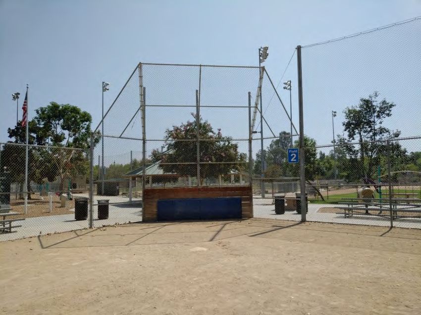
Separate pricing outlining the cost of caissons and slurry backfill for light poles and
      scoreboards poles shall be provide in the proposal pricing. If during construction, ground
      water is not encountered, the cost of this work will be deduced from the contract.

      Grading:
      The existing site shall be graded to maintain the existing relative grades on site as to not
      disturb the existing site drainage. Upon removal of existing turf grass, the existing field areas
      shall have any minor high/low areas graded to maintain neat consistent grades without
      requiring any import or export of fill from the site. The only foreseen removal of soil will be
      from the removal of turf grass or that required to place infield mix.

      Concrete Walkway, Dugout Concrete and Spectator Concrete:
      All concrete walkways shall be 4 inches thick and contain #3 reinforcing steel placed at 16”
      spacing on center both ways. Concrete shall be 560-C-3250 unless otherwise shown.
      Concrete subgrades shall be compacted to a relative compaction of 90%.

      Sports Field Infield Mix:
      All existing sports infield mix may be reused on site for the new infield areas in lieu of
      disposing and trucking new material on site. Additional infield mix shall be provided as
      necessary to ensure the entire area within sideline and outfield fencing has infield mix other
      than those area to receive field turf. Infield mix and field top soil shall not be intermixed with
      each other.

5.1.4 Chain Link Fencing, Backstops and Sideline Netting

      Chain Link Fencing:
      Provide all chain link fencing to encompass the entire field as shown on the site plan. Chain
      link fencing shall be galvanized, Class 1A, with 2-3/8” diameter minimum post size for line
      fencing and contain top and bottom rails. Outfield fencing shall be 6’ tall. Sideline fencing
      shall be 6’ tall from dugouts to outfields and 10’ tall from dugouts to backstops.

      Chain Link Gates:
      Provide one 10’ wide double swing chain link gate at each field, total of two, for equipment
      and maintenance access. Gates shall contain locking drop fork and rod type latches with
      guides and gate stop. Gate stop shall include a galvanized steep post anchored into a 10
      inch diameter by 12 inch deep footing.

      Provide four 36” wide, 7’ tall chain link gates per field, eight total, to provide field access and
      dugout access. Gates shall contain locking U-type latch. Chain link gates shall match
      existing chain link gates.

      Backstops:
      Provide one backstop per field, total of two, to match the existing backstops for the existing
      Fields No. 2, 3, & 4. Backstop shall include pressure treated 2x12 lumber and backstop
      padding to match existing field backstop padding. Lumber for backstops shall be free of open
      knots, splits, warps and shall be dried prior to installation. Lumber shall be lightly sanded to
      remove any splinters or excessive roughness. Required color is brown. Lumber shall be
      attached to dugouts with a 2x2 galvanized steel angle iron, 5’ long welded to each backstop
      pole and bolted with galvanized steel carriage bolts with bolt heads placed on the field side.

      Sideline Netting:

                                                  4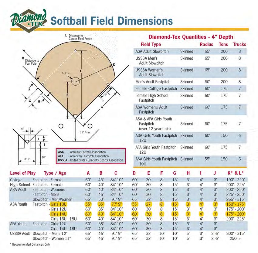
Provide 24’ tall sideline netting on both the 1st and 3rd baselines of each field from the
      backstop to the outfield end side of the dugouts to match the existing sideline netting on
      Fields 2 & 4. Netting material shall be in accordance to the City’s Approved Material List or
      approved equal.

5.1.5 Potable Water Infield System

      Backflow Preventer Enclosure.
      Provide backflow preventer enclosure with 4” thick concrete pad at existing potable water
      point of connection located at the entrance driveway and Cuyamaca Street. Anchor
      enclosure to concrete slab with vandal resistant concrete anchors. Provide expansion foam
      between existing piping and concrete foundation. Enclosure and concrete anchors shall be
      in accordance to the City’s Approved Material List or approved equal.

      Ball valves:
      Provide one ball valve for each field located outside of the sideline fencing.

      Provide one ball valve for the existing Fields 2, 3 & 4 at the field side of the sideline fencing
      at the existing mainline locations to provide isolation for existing quick coupling valves.

      Ball valves shall be installed in rectangular precast concrete boxes, with locking, hinging,
      precast cover and contain at least 6 inches of gravel bedding. Ball valves shall be 1” in size
      as shown on the City’s approved materials list for each quick coupling valve disconnect. A
      1.5” ball valve shall be provided at the point of connection and the adjacent ball valve box
      shall be replaced with precast concrete box.

      Mainline:
      Provide 1.5” and 1” mainlines as shown on the site plan (Exhibit ‘A’). Mainlines shall be
      Class 315 PVC, white in color and contain tracer wire. Tracer wires shall terminate into ball
      valve boxes and quick coupling valve boxes and include 24” of spare wire coiled with ID tag.

      Quick Coupling Valves
      Provide one potable water quick coupling valve for each field located behind the pitching
      mound as shown on the site plan. Quick coupling valve shall be 1” inlet as shown on the
      City’s approved materials list. Quick coupling valve shall be installed in 10” diameter precast
      concrete valve box with cast iron cover.

5.1.6 Landscape Irrigation

      Irrigation Layout:
      Existing landscape irrigation system is recycled water and will require the irrigation system to
      be reviewed by County DEH and the Padre Dam Municipal Water District for approval. The
      successful firm will be required to coordinate the review and approval with both agencies and
      pay for the associated plan check, inspection and cross connection testing.

      Contact: Padre Dam Municipal Water District, Development Services Department

      Irrigation work will require connecting to the existing 2” recycled water mainline, installing a
      2” ball valve and installing a 2” mainline the 3rd base line of the western U-10 softball field.
      Remote control valves for new turf grass shall be either 1” or 1.5” diameter brass valves.

                                                 5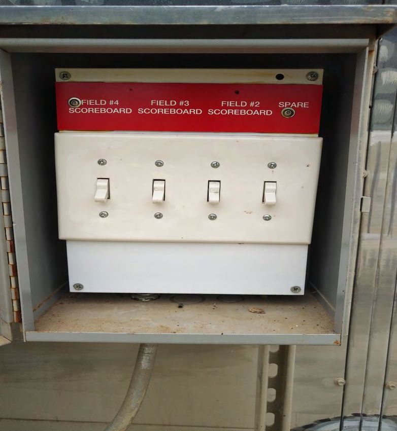
Valve banks shall be located outside of the field fence line, and the quick coupling valve shall
be located 1’ inside the fence line within a concrete valve box.

Master Valve and Flow Meter:
Install new 2” master valve and flow meter in separate boxes for ball field system just behind
the site meter. Install new master valve and flow meter wires through the existing conduit for
the adjacent master valve and flow meter that leads to the existing Calsense controller.
Provide 1” conduit between both master valves at the to provide pathway for control wires.
This eliminates the need for trenching conduit and wire to the new Calsense controller.

Wye Strainer and Pressure Reducing Valve:
Provide 2” ball valve, 2” wye strainer and 2” pressure reducing valve at existing recycled
water meter located at the entrance driveway and Cuyamaca Street.

Provide 2” ball valve and 2” pressure reducing valve at existing above ground wye strainer
located at the entrance driveway and Cuyamaca Street.

Pressuring reducing valves, wye strainers and ball valves shall be in accordance to the City’s
Approved Material List or approved equal.

Protection Enclosure:
Provide two protection cage enclosures with 4” thick concrete pad at both existing recycled
water irrigation points of connection located at the entrance driveway and Cuyamaca Street.
Anchor enclosure to concrete slab with vandal resistant concrete anchors. Provide
expansion foam between existing piping and concrete foundation. Enclosure and concrete
anchors shall be in accordance to the City’s Approved Material List or approved equal.

Controller:
Remove existing Hunter irrigation controller mounted to the eastern site of the electrical
distribution gear and extend existing control wires to new controller location. Install new
Calsense CS-3000 controller adjacent to existing dual Calsense ET-2000 controller.

New Calsense controller shall have the following features:
  • Calsense Model CS-3000 (24 Station)
  • Cellular Communication (CS3-GR)
  • Flow Sense Software (CS3-FL)
  • Weather Interface Kit (CS3-W-KIT)
  • Manufacturers stainless steel pedestal enclosure
  • Dedicated 120V electrical service run to new electrical cabinet.             See electrical
      subsection for further details.

The existing dual Calsense controller shall be upgraded to the CS-3000 type controller and
have manufacturers communication cable run underground between both controllers to
provide inter controller communication. The existing controller serial number are 34589 &
32697 which are required by Calsense to provide upgrade kits for.

Remote Control Valves:
Remote control valves shall be installed in purple plastic valve box and have “RCV”, the
controller letter and the valve number branded into the center cover with 1” high letters.
Remote control valve wire shall be installed in PVC conduit installed parallel to irrigation main
                                           6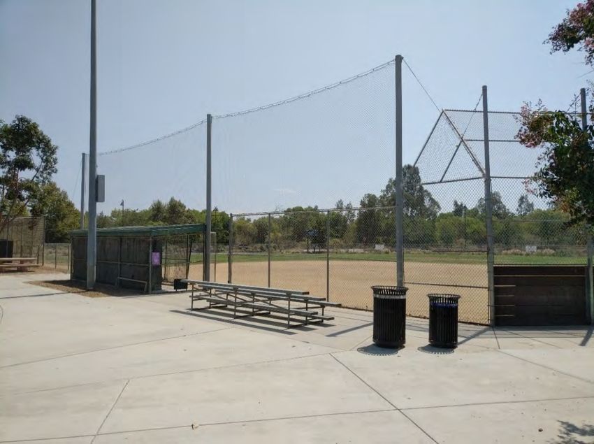
and terminate into the nearest remote control valve box. A separate 1” conduit shall be
     provided between each remote control valve box to provide a pathway to each remote control
     valve box at each valve bank. At least 24 inches of spare control wire shall be provided at
     each remote control valve box, be coiled and contain with valve ID tag and recycled water ID
     tag. ID tags shall be fastened with ¼” nylon zip ties. Valve banks shall contain a 2” ball valve
     to isolate the valve bank and quick coupling valve from the 2” mainline for maintenance
     purposes. Two spare valve wires and 1 spare common wire shall be provided at each valve
     bank.

     Mainlines:
     All irrigation mainlines shall be purple Class 315 PVC pipe for use with recycled water.
     Mainline fittings shall be schedule 80 PVC. A tracer wire shall be provided on all mainlines
     and terminate into the valve bank isolation valves and mainline valves. Tracer wire shall be
     connected to the mainline with ¼” wide nylon zip ties at least every 8 feet. Mainlines shall
     be installed to a depth of 24 inches below finish grade. Warning tape shall be installed 1’
     above all mainlines.

     Quick Coupling Valves:
     Two quick coupling valves shall be installed on each field. Locate quick coupling valves
     adjacent to the 1st and 3rd bases approximately 1-2 feet inside of the sideline fence. Quick
     coupling valves shall be installed in concrete valve boxes. A 1” supply line shall be provided
     to each quick coupling valve.

     Rotors:
     Irrigation rotors shall be installed with schedule 80 swing joints and provide full head to head
     coverage. Rotors spraying at 90°, 180° and 360° coverages shall be installed on separate
     zones to ensure matching application rates to ensure proper irrigation coverage. Mixing
     different rotor application rates will not be permitted.

     Recycled Water Signage:
     Six recycled water signs shall be provided at each field meeting the requirement of the Padre
     Dam Municipal Water District and County DEH. Recycled water signage shall be installed at
     the following locations:

        •   Two on each sideline fence
        •   Two on each outfield fence

5.1.7 Landscape Planting

     Field Turf:
     Grass turf for the sports field outfields shall be sodded grass turf. Turf shall be a warm
     season, hybrid bermuda grass, with salt tolerance and have excellent wear tolerance capable
     of handling stress from sports activities. Existing turf grass on adjacent softball fields is
     Tifway Bermuda grass. Turf shall be installed in in the entire outfield area and terminate 10’
     from sideline fencing to ensure a consistent 10 feet wide outfield and sideline warning tracks.

     Mulch:
     Any existing mulch in planters adjacent to field fencing shall be restored to their existing
     condition to provide a neat, clean appearance from existing planter areas to the new field
     fence lines.

                                                7
Mulch shall be installed between the new fields where grass currently exists and is shown to
be removed. See site plan for location.
Much shall be placed to a thickness of 3 inches. Mulch shall be free of any foreign materials
and shall be submitted for approval. Much shall conform to that shown on the City’s Approved
Materials List.
5.1.8 Sports Lighting Requirements
Sports Lighting:
Musco sports field lighting shall be provided for both of the new fields. The existing Field 1
has six 70’ tall Musco sports lighting poles and luminaires which may be salvaged and reused
for the new fields sports lighting system, however new LED light lamps shall be provided for
all existing luminaires. Sports lighting system shall be designed to match existing fields
lumen/foot candle design. A new circuit switch shall be provided for the existing control panel
which has room for spare circuits. The new circuit shall be labeled “Field 5”. Sports lighting
shall additionally be connected to the existing Musco Control Link for remote lighting
operation by league users.
Spare Conduit and Pull Box Circuit:
All new sports lighting poles shall be provided with a surface mounted 1” diameter EMT
conduit extending 16’ above ground for future use and terminate into an outdoor rated dual
gang electrical box with cover. This surface mounted conduit shall terminate into a 1-1/2”
PVC conduit that sweeps into a No. 3-1/2 concrete pull box with vandal resistant cover. A
1-1/2” conduit shall be run to each pole and terminate into a new pull box located at the
electrical distribution center for future use.
5.1.9 Site Electrical
Electrical Distribution and Load Center:
Remove existing electrical 3 phase load center panel with side mounted 50A twist lock
receptacles, transformer, scoreboard switch box, Hunter Irrigation controller enclosure and
support structure compromised of unistrut and surface mount anchors. Clean existing
electrical enclosure and equipment of any dirt/debris. Seal existing enclosure to concrete
pad with elastomeric joint sealer/caulking.
Repaint existing electrical distribution gear to match existing mural which will be blemished
with the removal of mounted equipment. Mural artist information is below:
Gorilla Team Artists
Thom Guerra
PO Box 1177
Alpine, CA 91901
619-916-6571
thomthesignpainter@yahoo.com
Place a standalone multi compartment commercial rated NEMA 3R electrical pedestal with
lever style locking doors. The intent is to provide a multi section pedestal that can be locked
independently for different users between City maintenance staff, little leagues, and
recreational event staff. The enclosure shall contain internally, a 200amp 120/240V load
center with a 200 amp main breaker, and at least 24 spaces to house the existing electrical
8circuits and provide not less than 6 spares circuits for future use. A 277/480V to 120/240V
transformer shall be housed inside the enclosure.
Either as part of electrical pedestal or mounted to the enclosure shall be a separate section
for event power. Event power shall contain two 50amp twist lock plugs and (3) 20amp
receptacles all on their own dedicated circuits.
The third section shall provide for switch control of the 5 scoreboards on site and provide 2
spare switchable sections for future use.
Pull Boxes:
Pull boxes shall have locking covers as manufactured by MR Steel with manufacturers City
of Santee specific locking bolt down cover. Bolt threads of locking covers shall receive an
application of anti-seize compound. All conductor circuits shall be labeled in each pull box
with waterproof labels.
Conduits:
All above grade conduits shall be galvanized steel or EMT, PVC is not permitted. Conduits
shall be sized to provide for 33% max full and shall be no smaller than 1”. Conduits ends in
pull boxes shall contain end bells. Upon completion of work all conduit ends shall be sealed
with conduit/duct compound, spray foam is not permitted.
Field Electrical Receptacles:
At each dugout location for both fields, a single double gang GFCI receptacle shall be
provided. Electrical receptacle shall be housed in a weather proof receptacle box with
hinging cover and be additionally housed in vandal resistant, stainless steel pad locking
enclosure. This enclosure shall be as manufactured by Vandal Stop, Model No. AA-EB-3R
or approved equal. The City will furnish the padlock at the completion of work.
5.1.10 Site Furnishings
The following site furnishings shall be furnished and installed as required below:
Dugouts:
Two dugouts shall be provided for each field, total of 4. Dugouts shall match the existing size,
shape and components of the existing fields. Dugout roofing is 22 gauge standing seam
metal roofs,16” rib spacing with custom color: Hemlock Green. Metal roofing shall be
installed over 30# asphalt roofing felt. All lumber shall be grade 1 or better and primed and
painted with two coats of exterior grade paint, color hemlock green. Dugouts shall be provided
with heavy duty black windscreen with metal grommet connections fasted with galvanized
steel wire or galvanized hog rings to provide a tight secure installation.
Base Plates, Ground Anchors and Plugs:
One home plate, 1st base double plate and base plates for 2nd and 3rd base shall be provided
for each field. Seven base anchors and seven base plugs shall be provided for each field due
to the dual U10/U14 softball use.
Home plate, base plates, ground anchors and plugs shall be as manufactured by Patterson
Williams or approved equal to the quality of the products listed below:
Home plate: Model No. 8500-00
91st Base Double Plate Model No. 8505-00
2nd & 3rd Base plates: Model No. 8504-00
Ground anchors: Model No. 8502-01
Plugs: Model No. 8502-02
Field Name Signs:
Four field signs shall be provided at each field, total of 8. Field signs shall state “Field 1” and
“Field 5” respectively. Signs shall be aluminum with blue background, white letters, and white
border matching the existing field signs on site. Signs shall be mounted to chain link fencing
with vandal resistant hardware shown of the City’s Approved Material List.
Outfield Distance Signs:
Three field distance signs shall be provided per field, total of six. Outfield distance signs shall
be located at the first base line, third base line and center field. Signs shall be 18” x 30”
aluminum sings with blue background, white letters, and white boarder. Signs shall be
mounted to outfield chain link fencing with vandal resistant hardware shown of the City’s
Approved Material List.
Dugout Signage:
Two dugout signs shall be provided at each field, total of four. Dugout signs shall state
“Visitor” and “Home” respectively. Home sign shall be placed on the 3rd baseline dugout and
Visitor sign shall be placed at the 1st base line dugout. Signs shall be 16” x 8” aluminum
sings with blue background, white letters, and white boarder. Signs shall be mounted to
outfield chain link fencing with vandal resistant screws as shown on the City’s Approved
Materials List.
Dugout Benches:
Two dugout benches shall be installed at each dugout, total of eight. Dugout benches shall
be steel, expanded mesh type metal, black in color. Dugout benches shall be as
manufactured by Anova, Victory Model No. D1065, surface mount or approved equal.
Benches shall be anchored to dugout concrete with vandal resistant concrete anchors as
shown of the City’s Approved Materials List.
Bleachers:
Two bleachers for spectator seating shall be provided at each field, total of four. Bleachers
shall be 3-tier, 15’ long, 6061 aluminum with foot boards. Bleachers shall be as manufactured
by Belson, Model No. 109 or approved equal. Bleachers shall be anchored to dugout
concrete with vandal resistant concrete anchors as shown of the City’s Approved Materials
List.
Bat Holders:
One bat holder shall be provided at each dugout, total of four. Bat holder shall hold 15 bats,
be surface mounted be anchored to dugout concrete with vandal resistant concrete anchors
as shown of the City’s Approved Materials List. Bat holders shall be as manufactured by
Steelcraft, model number LA-BR-15SMPC or approved equal.
Foul Line Poles:
Two foul line poles shall be proved for each field, total of four. Foul line poles shall be 3-1/2”
diameter OD, 12’ tall, steel with 12” wide x 6’ tall flag. Foul line poles shall be in ground
anchored per manufacturers recommendations. Foul line poles shall be as manufactured by
Patterson Williams, Model No. 1267, color yellow or approved equal.
10Scoreboards:
Provide one score board for each field, total of two. Scoreboards shall match existing
scoreboards to maintain consistent appearance and maintenance for City staff. Existing
scoreboards are manufactured by Varsity Scoreboards, Model No. 3314, Color: black.
Install scoreboards per manufacturers recommendations with 6” diameter galvanized steel
pipe supports, painted black to match existing scoreboards. Scoreboards shall be located at
the center of center outfield field with support poles centered 3’ behind the outfield fence.
Any external mounted conduit for power and control wires shall be placed in galvanized steel
EMT tubing.
Scoreboard Controller Enclosure:
Provide 1 enclosure per field, total of two to house the scoreboard controller for each field.
Scoreboard controller enclosure shall be 12x12x6, hinging door, pad locking and stainless
steel as manufactured by Wire Guard Systems, Model No. 667k or approved equal.
Enclosures shall be mounted to the outside of the backstops with stainless steel vandal
resistant screws as shown on the City’s Approved Materials List. The City will furnish the
padlock required for the enclosures.
Equipment Boxes:
Provide 1 steel equipment storage box enclosure per field, total of two. Steel equipment
boxes shall be 14-gauge steel, painted green or black, 60” wide, 24” deep and at a minimum
28” high, contain sloping lid and 2 recessed locking areas for pad locks. Enclosure shall be
painted black or green and contain integral legs that elevate the bottom of the enclosure off
of the concrete pad. Enclosures shall be installed on a single 4” thick concrete pad and
anchored with vandal resistant concrete anchors as shown of the City’s Approved Materials
List. Enclosure padlocks will be provided by the City.
Backstop Padding:
Provide 1 backstop padding for each backstop, total of two. Anchor to 2x12 pressure treated
backstop lumber with stainless steel vandal resistant screws and washer through
manufacturers perimeter grommets. Padding shall be 4’ tall, 12’ wide and 3 inches thick.
5.2 Project Design
5.2.1 General
The City will provide to the Firm, the asbuilt drawings for the existing Town Center Community
Park West site. In addition, the City will identify the existing features on site should the firm
have questions interpreting the asbuilt drawings. The Town Center Community Park West
facility was constructed in multiple phases, therefore several separate project plan sets will
be required to be reviewed to accurately determine all existing facilities on site.
The firm shall provide all plans on City title block necessary to obtain approval of the recycled
water irrigation system by the Padre Dam Municipal Water District and County of San Diego
Department of Environmental Health. Plans must be signed by a State of California licensed
landscape architect or Civil Engineer. In addition, the Firm will be required to provide a
revised site plan, electrical plan, sports lighting plan and irrigation controller charts. Existing
details from asbuilt drawings can be referenced in lieu of preparing new detail sheets.
The existing Town Center Community Park site was designed by PSOMAS in the late 2000’s.
The Firm at their sole discretion may contact PSOMAS to sub-consult for any past electronic
11files, AutoCAD files, etc. to facilitate with their design and be responsible for any sub-
consulting fees by contacting:
Sarah Curran, Vice President
PSOMAS, San Diego
(619) 961-2800.
Design will require the use of a private underground utility locator to verify the locations of
the City owned water, electrical and communication lines that are not covered under the
Underground Service Alert (USA) notification system.
5.2.2 Design Submittals
The Selected firm shall provide two design submittals at 50% and 100% design phases,
though additional submittals may be provided by the Firm to the City to prevent any
unforeseen design changes. The design shall match the existing ball field features, with
revisions to the site plans, electrical and sports lighting and irrigation designs. In order to
meet the project schedule, site demolition work may be completed during the final 50%
design phase.
5.2.3 Design Record Drawings
The record drawings below are provided for reference to demonstrate the existing conditions
on site:
• Safety Netting
Town Center Community Park West Safety Netting, CIP 2016-32
• Site Irrigation (Non-Field Areas)
Town Center Community Park Irrigation, CIP 2006-33
• Restroom Building
Town Center Community Park West Restroom Building, CIP 2004-34
• Sports Lighting
Town Center Community Park West Ball Field Lighting, CIP 2004-33
• Fencing and Backstops
Town Center Community Park West Fencing, CIP 2004-33A
• Field 1 & 2 Ball Field Irrigation
Town Center Community Park West, Field 1 & 2 Irrigation Modifications
These drawings are available for download and a link will be provided to all proposers upon
request.
5.3 Project Management
The selected Firm shall provide all project management necessary to ensure fulfillment of the
scope of work and all required items to complete the project including all required design,
permitting, implementation, installation, construction, quality control, and project close out
items within the contract and schedule. The Firm is expected to provide continuous Quality
Assurance and Quality Control during the design and installation and close out activities.
5.4 Use of Project Site
During the performance of the contract, the Firm will have full use of Field 1 to perform all
aspects necessary to complete the project. All equipment, material and other necessary
12storage shall be on the Field 1 area only to maintain the parking on the surrounding parking
lot for public use of the park facility. The City at all times shall have access to the site to
inspect and ensure the required work items completed by the Firm are being met. The Firm
shall provide any required security fencing, cover, or other means necessary to protect the
site.
5.5 Proof of Performance
Key components of the system are to be, tested and demonstrated to the end users at the
project site to ensure all systems and equipment will adequately meet the needs required for
the project. The following items will be minimum inspections by the City to ensure the project
performs as required:
• Electrical conduits installed have been verified clean by the pulling of mandrels
through conduits and blow clean of any dirt/debris or other foreign materials.
• The City’s Building Department has inspected the electrical work and copies of the
final inspection has been provided.
• The new potable and recycled water main lines have been pressure tested for a
period of 24 hours to ensure no leaks are present.
• Mainline tracer wires have been tested for continuity.
• The site has been inspected by the Padre Dam Municipal Water District and County
Department of Environmental Health and the potable and recycled water facilities
installed as part of this contract have been approved for use of recycled and potable
water.
• The Musco Sports field lighting system is fully operational and can be controlled
remotely via the Musco Control Link system. Night time test has been completed
demonstrating the design lumen/foot candle output.
• The scoreboards controllers can be turned on/off via the installed electrical switches,
the switches have been properly labeled and the new scoreboards are fully
operations when controlled by their corresponding wireless controller.
• The Calsense Irrigation controllers are fully operational, remote control valve stations
have been assigned and programmed including soil type, plant type, emitter flow
rate. The Calsense manufacturer’s representative has inspected the controllers and
provided in writing that the system has been installed to the manufacturers
requirements.
• Not less than two agronomist tests have been performed for each turf field to
determine the appropriate agricultural suitability for the sod turf soil.
• The 90-day landscape maintenance period has been completed and no damages, or
other related items are seen regarding the fields sod turf. Fertilizer has been placed
in two separate applications over the sod turf at least 45 days from each application.
5.6 Project Submittals
Product Data: Submit manufacturer's product data sheets for each item that will be provided
as part of this contract. Submit electronically as a single PDF, or of required, hard copies per
project requirements. All equipment cut sheets will be arranged per section. Provide a table
of contents and a bookmark at the start of every product sheet.
Shop Drawings: Submit project shop drawings for review and approval prior to ordering
equipment. Failure to submit shop drawings with ample time for evaluation shall not entitle
the contractor to an extension of contract time. There will be no work authorized on site
without the prior submittal and subsequent approval of a complete set of shop drawings. Any
13exceptions to this must be in writing and approved by the City. Shop drawings shall indicate
complete details and dimensions of work to be performed. Shop drawings shall be formatted
as outlined below, and should contain the items as appropriate, but are not be limited to, the
following details:
5.7 Contract Closeout Submittals
1. Submit all contract closeout documentation within 30 days after substantial completion,
unless otherwise noted.
2. Contractor shall work from approved drawings or approved shop drawings only. Note
changes made during installation on a single set of drawings in red. This set of marked up
drawings will not leave the jobsite until after the final system commissioning. Submit
electronic corrected sets of drawings showing work as installed. All “as-built” drawings to be
provided both in electronic form (AutoCAD version 2018 or later) and in Adobe PDF (same
size as project drawings).
3. Contractor to provide an Operation and Maintenance Manual prior to acceptance testing.
Provide a minimum of 1 hard copy and one electronic copy in PDF format. This manual shall
contain the following information:
a. Table of Contents.
b. Contractor’s contact information for warranty and/or service.
c. Manufacturer warranties for all equipment.
d. A complete list of equipment, both installed and loose gear. Include manufacturer,
model number, and serial number for all devices. Include settings (software or
hardware) for any devices that required modification or adjustment during the
acceptance testing.
e. Operating manuals for each device.
f. Documentation of all testing results.
g. A USB drive containing all As-Built drawings in PDF & AutoCAD (DWG) format.
h. Replacement parts lists of major items of equipment.
i. Provide a suggested schedule of routine maintenance. Schedule should include
dates of inspections, cleaning, maintenance, required cleaning/maintenance
materials, replacement of batteries (if applicable) and all other items to maintain the
work for its life expectancy.
j. Create a quick start guide to provide information specific to the system, such as
procedures for system power on/off, patching, different modes of operation etc.
i. The guide should convey information specific to the installed system.
ii. Anticipated length of the guide is less than 2 pages front and back.
4. Provide two copies of all software installed on computers or equipment in the system,
including all device configuration files on a USB disk.
5. Asbestos and PCB Certification: After completion of installation, but prior to Substantial
Completion, Contractor will certify in writing that products and materials installed, and
processes used, do not contain asbestos, lead, or polychlorinated biphenyls (PCB).
6. Provide a complete list of spares inventory to include quantity, manufacturer, model number,
and serial number.
5.8 Warranty
14The firm shall warrant all materials and workmanship for not less than two years after the
date of acceptance by the City Council. Defects occurring in labor or materials within the
warranty period shall be rectified by replacement or repair. Within the warranty period,
provide answer to service calls and requests for information within a 24-hour period, and
replace any faulty item within a 72 hours period without charge including parts, labor,
shipping, and travel times. Warranty documents shall state beginning and ending dates of
the warranty period. This information shall also be stated on the record drawings.
Contractor to provide final site visit and verification that the system is operational and all items
are functioning correctly at the end of the warranty period. The contractor shall not be
responsible for correcting items that have been changed by the City.
6 PROPOSAL FORMAT AND CONTENT
Proposals should be concise but provide sufficient detail to enable the City to conduct an
operational evaluation of the proposal. Proposals should clearly demonstrate the firm’s
qualifications and experience with similar projects and services, as well as the qualifications
and competence of the particular staff to be assigned to this project. It should also specify
the firm’s methodologies and approach to meet the RFP requirements. Figures should be
clearly explained in a narrative or in footnotes, as necessary.
Firms may provide more information as deemed appropriate, but are required to follow the
general outline and include the minimum information presented below. The substance of
proposals will carry more weight than their form or manner of presentation.
6.1 Transmittal Letter / Executive Summary
A signed letter of transmittal briefly stating the firm’s understanding of the work to be done
and why the firm believes it is the best qualified. Include an overview that highlights the firm’s
approach to the project and its commitment to meet or exceed the City’s objectives and
ensure the project is successfully completed on time and within budget. Also Include:
• The title and date of the proposal
• The firm’s legal name and address
• Legal form of business (sole proprietor, partnership, corporation, joint venture, etc.) If the
company is a joint venture or consortium, the qualifications of each firm comprising the
joint venture or consortium should be separately identified and the firm that is to serve as
the principal should be noted, if applicable
• Year firm was established
• Name, title, address and contact information (phone and e-mail) of the person to contact
regarding the proposal
• Name, title, address and contact information (phone and e-mail) of the main point-of-
contract/project manager to be assigned to the project
• Company website, if any
6.2 Experience, Technical Competence & References
Describe the firm’s qualifications, competence, capacity and resources to perform the work.
Include the firm’s experience in completing similar projects. Specifically, include specific
project experience related to the project. Also describe the firm’s experience working with
15state or local government agencies and give an indication of the firm’s understanding of local
government regulations, state and local building codes and other local guidelines and criteria.
Identify up to five (5) successfully completed projects of similar nature within the last five (5)
years. Highlight any projects where the team identified for this proposal has worked together
in the past. Include three (3) to five (5) client references, outlining:
o Company names and addresses
o Names and telephone numbers for primary contact persons
o Project amounts
Describe the firms experience with equipment and systems of the types specified, shall
maintain a fully staffed and equipped service facility, and shall be a franchised dealer and
authorized service facility for the major brands specified.
6.3 Staffing Plan and Key Personnel
Describe the staffing plan and provide an indication of the total staffing level for the project,
including project management staff, design professionals, lead engineer/architect, engineers,
contractors and use of subcontractors. Identify the roles and responsibilities of key personnel
who will perform the work and provide a brief resume for each. The information provided
should demonstrate the qualifications of the particular staff to be assigned to this project.
All terms of the contract, including qualification statements shall apply to subcontractors.
Provide a scope of work outlining what portions of the project for which a subcontractor will
be responsible.
6.4 Licensing and Professional Certifications
Provide a list of all licenses and professional certifications currently held by the firm or sub-
consultants and the staff who will perform the work. At a minimum:
• The firm shall be a State of California issued, Class A, General Engineering Contractor.
• Concrete work shall be complete by a C-8 Concrete or Class A General Engineering
Contractor.
• Electrical and sports lighting work shall be completed by a C-10 Electrical Contractor.
• Fencing and backstop work shall be completed by a C-13 Fencing Contractor.
• All landscape and irrigation work shall be completed by a C-27 Landscape Contractor.
• All landscape irrigation plans shall be prepared by a licensed Landscape Architect or
Civil Engineer.
Failure to possess the applicable licenses as specified shall render the proposal as non-
responsive.
6.5 Proposed Method to Accomplish the Work
Describe the firm’s technical and management approach to complete the project. Provide a
preliminary project schedule reflecting major activities, task-related milestones, and an
outline of deliverables and anticipated project completion. Describe any variations from the
Scope of Services that will enhance the outcome.
Describe the firm’s plan for ensuring appropriate communication and responsiveness to the
City’s needs, including the firm’s plans for written and/or verbal updates/meetings (i.e. daily,
16weekly, or bi-weekly review meetings as needed); and the firm’s representative for purposes
of being the City’s single point of contact on a day-to-day basis (i.e. project manager).
Outline any anticipated data, information or materials needed from the City to complete the
project, which was not obtained or provided during the mandatory pre-proposal meeting.
Include a sample set of shop drawings or as-builts documents that demonstrate the firm’s
capabilities to provide engineering and documentation for the project. Provide a line sheet
listing all manufacturers for with the firm is a deal and/or authorized service center. Include
a description of the firm’s abilities for in-shop assembly, fabrication and testing.
To ensure that practices and procedures are consistent with measures to help limit the spread
of COVID-19 while carrying out operations, the City continues to closely coordinate with, and
monitor information and updates from the Centers for Disease Control and Prevention (CDC),
the California Department of Public Health (CA DPH), the San Diego County Health and
Human Services Agency, and others related to COVID-19. Per the County of San Diego
Public Health orders, facial coverings are required. In addition, essential businesses, must
create and post COVID-19 protocols for appropriate guidelines, behavior, and sanitation at
each business, and facility. For the latest information and guidance, please refer to:
https://www.sandiegocounty.gov/content/sdc/hhsa/programs/phs/community_epidemiology/
dc/2019-nCoV/health-order.html
6.6 Pricing / Fee to Perform Service
Outline a comprehensive cost estimate that takes into consideration all pre-installation,
inspection or design services, materials, construction/installation, and disposal costs. The
proposed costs should contain all pricing information relative to performing the work as
described in this RFP.
• Total contract price with the following breakdown:
o Demolition & Clearing
o Site Work
o Chain Link Fencing, Backstops, and Sideline Netting
o Potable Water System
o Landscape Irrigation
o Landscape Planting
o Sports Lighting System
o Electrical System
o Site Furnishings
o Storm Water BMPs
• Itemized equipment list with quantities and unit pricing.
• Breakdown of the number of labor hours for each of the following:
o Engineering and documentation
o On site coordination meetings and supervision
o In shop fabrication and assembly.
o On site fabrication, assembly and installation.
o On site verification and testing.
17You can also read


