TROUBLESHOOTING VOICE-OVER-IP (VOIP) IMPAIRMENTS IN A DOCSIS NETWORK - EXPO APRIL 4, 2006
←
→
Page content transcription
If your browser does not render page correctly, please read the page content below
TROUBLESHOOTING VOICE-OVER-IP (VOIP)

 IMPAIRMENTS IN A DOCSIS NETWORK

                        AUTHORED BY BRADY VOLPE

                                 PRESIDENT

                              THE VOLPE FIRM

                          WWW.VOLPEFIRM.COM

                                   EXPO
                               APRIL 4, 2006

                                                                                          1

    TROUBLESHOOTING VOICE-OVER-IP (VOIP )IMPAIRMENTS IN A DOCSIS NETWORK | www.volpefirm.com
Troubleshooting VoIP in a DOCSIS Network
TABLE OF CONTENTS
Brady Volpe................................................................................................................................................ 1
President .................................................................................................................................................... 1
The Volpe Firm ........................................................................................................................................... 1
www.volpefirm.com .................................................................................................................................. 1
Table of Contents ........................................................................................................................................... 1
Section 1: Overview ........................................................................................................................................ 3
Section 2: DOCSIS Primer ............................................................................................................................... 3
Section 3: VoIP Primer .................................................................................................................................... 4
Section 4: Call Quality ..................................................................................................................................... 5
Section 5: DOCSIS Impairments ...................................................................................................................... 6
Downstream RF Impairments .................................................................................................................... 8
Upstream RF Impairments ......................................................................................................................... 9
Call Signaling and VoIP Traffic Flows ....................................................................................................... 10
Section 6: VoIP Impairment Types ............................................................................................................... 12
Packet Loss............................................................................................................................................... 12
Delay ........................................................................................................................................................ 16
Algorithmic Delay .................................................................................................................................... 17
Packetization Delay .................................................................................................................................. 17
Serialization Delay ................................................................................................................................... 17
Propagation Delay ................................................................................................................................... 18
1
TROUBLESHOOTING VOICE-OVER-IP (VOIP )IMPAIRMENTS IN A DOCSIS NETWORK | www.volpefirm.comTroubleshooting VoIP in a DOCSIS Network
Component Delay .................................................................................................................................... 18
Jitter (Delay Variation) ............................................................................................................................. 19
Section 7: Summary and Conclusions ........................................................................................................... 19
References .................................................................................................................................................... 21
2
TROUBLESHOOTING VOICE-OVER-IP (VOIP )IMPAIRMENTS IN A DOCSIS NETWORK | www.volpefirm.comTroubleshooting VoIP in a DOCSIS Network SECTION 1: OVERVIEW This paper will discuss troubleshooting Voice-over-Internet Protocol (VoIP) in a DOCSIS® (Data-over-Cable System Interface Specification) network. It will begin with the method by which cable operators provide voice services over a data network. This is will start with DOCSIS and VoIP primers in order to provide a common foundation of terminology and understanding of the subject matter. Once a foundation has been provided, the paper will focus on three (3) high level VoIP impairments, Packet Loss, Delay (also referred to as “Latency” interchangeably), and Jitter. These three components are responsible for nearly all VoIP call degradation, but the underlying manifestation of the components may be the result of a complex number of factors in the distribution network. While some of the impairments can be corrected in the transport mechanisms supporting the VoIP call, some cannot. This leads to the need for advanced techniques of minimizing the effects of packet loss, delay, and jitter. If the impairments cannot be minimized below a certain threshold, the user (hereon referred to as the “caller”) will experience poor voice call quality, analogous to many Public Switched Telephone Network (PSTN) related impairments, such as echo, noisy background, distorted voices, and talker delay. Minimizing these perceived impairments is what will ultimately win or lose the battle for voice services by cable providers. SECTION 2: DOCSIS PRIMER DOCSIS is effectively a transparent Ethernet bridge over an HFC network. There are two (2) functional components in a DOCSIS network, the cable modem (CM) on the subscriber side and the Cable Modem Termination System (CMTS) in the headend or hub site. The CMTS communicates with the CMs on a 6 MHz wide (8 MHz Euro-DOCSIS), RF amplitude modulated, 64- or 256-QAM digitally encoded signal on the downstream path of an HFC network between 88 and 860 MHz. The CMs communicate with the CMTS using a QPSK, 8-, 16-, 32-, or 64-QAM digital signal, also amplitude modulated and up converted to an upstream HFC frequency between 5 to 42 MHz (5-65 MHz Euro-DOCSIS). The digital data, transported via amplitude modulated carriers, contains Media Access Control (MAC) information which enables the CMs to coexist with other CMs by using a Time Division Multiple Access (TDMA) scheme [DOCSIS 2.0 also supports synchronous spread spectrum multiple access (S-CDMA)]. In essence, the CMTS is the system scheduler which coordinates the power level, frequency, transmit time, and pre-equalization of all CMs on the DOCSIS network. By virtue of the fact that CMs and the CMTS are capable to communicate digital data with each other over the HFC network for the purpose of “command-and-control” processes, they are also able to transmit packets containing other non-DOCSIS MAC related data. This is what fundamentally facilitates the ability to send Ethernet traffic bi-directionally over and HFC network. The CMTS-CM DOCSIS network transports IP based traffic in the same method that is used to communicate MAC protocol between the devices. Now that the IP traffic is can traverse the HFC network, end users are also able to utilize this network for 3 TROUBLESHOOTING VOICE-OVER-IP (VOIP )IMPAIRMENTS IN A DOCSIS NETWORK | www.volpefirm.com
Troubleshooting VoIP in a DOCSIS Network

the purpose of transmitting content destined for the multitude of available data network services such as
email, web browsing, IP video, and IP Telephony (VoIP).

In summary, each user is assigned a unique cable modem, which conforms to the DOCSIS specification.
The CMTS works as a system scheduler enabling many cable modems to reside on the same RF network.
TDMA and/or S-CDMA is employed in cable modem communications so that each user is allocated a
certain finite time over which they may transmit and receive IP data. IP data destined for a particular user
is sent to that user by the CMTS on a downstream RF channel. This is the way an Ethernet network is able
to be transparently bridged from a data backbone to a subscriber’s home or business location.

SECTION 3: VOIP PRIMER

Packet voice systems, those systems which enable VoIP, accept analog voice signals from telephone
handsets or PSTN networks. The analog signal is first digitized and coded, typically using the ITU-T G.711
PCM standard or the ITU-T G.729 standard, which offers compression. The decision to use a compression-
less CODEC such as G.711 or compression-based CODEC such as G.729 is usually a decision left to the
system operator. Signals using compression will create less network traffic, but some call quality will be
lost. Non-compressed signal will have the greatest call quality, but only if it does not over-burden the
data network with traffic, causing degraded call quality.

Now that the analog speech has been digitized, possibly compressed, and encoded, it is injected into IP
based networks (usually Ethernet) as data traffic. In order to co-exist with the other traffic on an IP
network, the voice stream must be broken into small packets. Generally voice streams are broken into 20
ms long packets. This time interval is often chosen so that a loss of one packet will have an unperceivable
impact on the voice call. The 20 ms packet size is also optimal for CMTS utilization, which creates 50
packets per second (pps) of voice traffic. Smaller packetization sizes of 10 ms create 100 pps, which
unnecessarily loads the CMTS, causing excessive CMTS CPU utilization during heavy call times.
Additionally, 20 ms packetization keeps the packet size relatively small, as compared to 30 ms or 40 ms
packetization times. In the case of G.711 with a packetization period of 20 ms, the payload will be 160
bytes. This will result in a total DOCSIS frame length of 232 bytes, which includes the necessary overhead
to properly route the packet in the DOCSIS data network. *Although the term “frame” is the appropriate
name for a packet of data with the associated overhead bytes for network routing, this paper will
generally refer to frames as packets, because it is the payload portion of the frame that is under
consideration.]

As will be discussed in more detail later, packets associated with voice services will usually be assigned a
priority over non-time sensitive traffic, such as email or web-based traffic, in order to assure a higher
quality of service (QoS). Since the voice call is now in a format compatible with Ethernet, it is able to be
transported over an HFC network using the DOCSIS transport specification. This enables users with cable
                                                                                                               4
modems and Multi-media Terminal Adapters (MTAs) in their homes and businesses to access data and

  TROUBLESHOOTING VOICE-OVER-IP (VOIP )IMPAIRMENTS IN A DOCSIS NETWORK | www.volpefirm.com
Troubleshooting VoIP in a DOCSIS Network
voice services over the same network, providing the infrastructure is in place. [Note: Typically cable
modems and MTAs are packaged as a single unit, called an eMTA for embedded MTA. This implies that
the MTA has a resident cable modem on board.]
SECTION 4: CALL QUALITY
In contrast to standard data communications, where communication quality is quantified in objective
terms of Bit Error Rate (BER), call quality is a subjective measurement. The subjectivity of call quality is
largely due to the fact that the human ear and brain can automatically correct for a certain level of
impairments during a conversation. So even though BER may be poor, the ear-brain combination may
enable the caller to consider a call as high quality because the impairments are relatively imperceptible,
whereas a computer may reject packets with even one error which is not corrected by employed error
correction codes.
This section will discuss the following two primary methods for quantifying call quality, Mean Opinion
Score and E Model. The first is Mean Opinion Score (MOS), whereby a panel of “listeners” subjectively
rate a given voice call on a scale of one to five. The mean of the listener’s ratings is then used as the
1
decisive scale for call quality. MOS is the mostly widely used voice quality metric.
The second method is the E Model. The E model is defined in the ITU-T G.107 standard as an R factor
with a metric from 0-100. The basic formula for determining the R factor is:
R = Ro – I s – I d – I e + A
Where Ro is a base factor determined from noise levels, loudness, etc. Is represents impairments
occurring simultaneously with speech, Id represents impairments that are delayed with respect to
speech, Ie represents the so-called “equipment impairment factor” and A is the “advantage factor” of
2
using that particular voice service. Assuming an “ideal” network, the maximum obtainable R factor for a
3
G.711 encoder is 93 while a G.729 encoder is 83.
5
TROUBLESHOOTING VOICE-OVER-IP (VOIP )IMPAIRMENTS IN A DOCSIS NETWORK | www.volpefirm.comTroubleshooting VoIP in a DOCSIS Network
Table 1 shows the “user opinion” as a function of the computed R factor and tested MOS score.
User Opinion R Factor MOS Score
Very satisfied (Toll Grade) 90 – 100 4.3 – 5.0
Satisfied 80 – 90 4.0 – 4.3
Some users satisfied 70 – 80 3.6 – 4.0
Many users dissatisfied 60 – 70 3.1 – 3.6
Nearly all users dissatisfied 50 – 60 2.6 – 3.1
Not recommended 0 – 50 1.0 – 2.6
4
Table 1. Acceptable MOS and R Scores
SECTION 5: DOCSIS IMPAIRMENTS
While seemingly simple in concept, the actual implementation of DOCSIS networks has many complex
pitfalls which cause impairments and failures in the communications network. Impairments at the
physical RF transport layer can manifest in poor or lost communications at the IP layer. Interoperability
issues between various DOCSIS devices (multiple vendors of CMTS and CM devices) in addition to over-
utilization of the DOCSIS network can result in frame loss, delay and jitter. Finally, all of the standard
impairments that exist in Ethernet networks are also present in Ethernet networks over DOCSIS, such as
collisions, delay, buffer-over flows, and routing errors, which results in frame loss, delay and jitter. So the
DOCSIS network experiences all of the problems of a standard Ethernet network, while at the same time
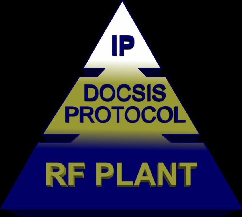
adding two additional levels of impairment probabilities; RF and DOCSIS protocol. Figure 1 shows a
graphical top-down representation of a DOCSIS network, which provides a visual reference of the
interaction of the RF plant, the DOCSIS protocol and the IP protocol levels built upon one-another. If any
layer of the pyramid experiences impairments, the whole network feels the impact and VoIP quality is
degraded.
6
TROUBLESHOOTING VOICE-OVER-IP (VOIP )IMPAIRMENTS IN A DOCSIS NETWORK | www.volpefirm.comTroubleshooting VoIP in a DOCSIS Network
The following sections summarize the impairments that may exist at each level of Figure 1.
Figure 1. DOCSIS Network Functional Layers
7
TROUBLESHOOTING VOICE-OVER-IP (VOIP )IMPAIRMENTS IN A DOCSIS NETWORK | www.volpefirm.comTroubleshooting VoIP in a DOCSIS Network
Downstream RF Impairments
The DOCSIS specification defines the minimum requirements needed for the downstream path of the HFC
network to be “DOCSIS compliant”. The main components of this specification are as follows:
Analog Measurements
o CNR ( ≥35 dB per DOCSIS spec)
o CSO ( ≥41 dB per DOCSIS spec)
o CTB ( ≥41 dB per DOCSIS spec)
Analog (Digital) Measurements
-8
o BER (post-FEC 10 or less per DOCSIS spec)
-8
Beyond CNR, CSO and CTB, the post-FEC error rate of 10 is the single greatest metric for downstream
signal quality. It allows one to base other downstream signal metrics, such as Modulation Error Ratio
(MER), a quantitative measurement of the voltage and phase error of a demodulated digital signal. Table
2 shows the minimum (left value) and recommended (right value) of MER required to support a given BER
-8
level. DOCSIS requires 10 post-FEC BER, which will result in no lost VoIP frames due to RF impairments.
-6
BERs of 10 or less are not recommended for VoIP.
-8
Table 2. Acceptable MER Scores for 10 post-FEC BER.
8
TROUBLESHOOTING VOICE-OVER-IP (VOIP )IMPAIRMENTS IN A DOCSIS NETWORK | www.volpefirm.comTroubleshooting VoIP in a DOCSIS Network
Upstream RF Impairments
The upstream path in an HFC network can be considered the Achilles heel of a VoIP system since it
contains the greatest source of impairments. A short list of the impairments follows, along with their
DOCSIS specification as applicable:
Linear Impairments such as:
o Micro-reflections -10 dBc @ 25 dB per DOCSIS)
The wide variety of upstream impairments causes data carrying signals from cable modems and eMTAs to
become corrupted before they reach the CMTS. If the CMTS is unable to demodulate a corrupted signal,
it discards the frame. In normal data traffic, the data will be re-transmitted by a higher level application,
but for VoIP, there is no such thing as a re-transmission since VoIP is a Real-Time-Protocol (RTP).
Therefore, any lost frames are gone for good!
The best way of detecting noise in the upstream is by setting a spectrum analyzer on MAX-HOLD
(maximum hold) at the headend or hub on the return path that goes to the CMTS upstream port. Keep in
mind that even though the return path is defined as 5-42 MHz, the return path lasers transport 5-200
MHz, so one will gain much more information about the system if the spectrum analyzer is set with a span
of 200 MHz.
Figure 2 shows a spectrum analyzer set with a span of 200 MHz. The upstream DOCSIS channel is the
rd
highest signal. There is also a 3 harmonic and a complete image of the 5-42 MHz pass-band and DOCSIS
9
TROUBLESHOOTING VOICE-OVER-IP (VOIP )IMPAIRMENTS IN A DOCSIS NETWORK | www.volpefirm.comTroubleshooting VoIP in a DOCSIS Network
carrier above 140 MHz. This is a clear indication that the laser is in compression and a likely culprit for
dropped VoIP packets due to laser clipping.
DOCSIS CH.
DOCSIS 3rd DOCSIS Image
Harmonic
Figure 2. Return Path Spectrum with 200 MHz Span and Laser in Compression
CALL SIGNALING AND VOIP TRAFFIC FLOWS
During a VoIP call, there are two distinct sessions. First, there is the call signaling session that sets up and
eventually tears down the call. Second, there is the call session itself, which in a DOCSIS 1.1 or higher
network, should reside in a service flow which ensures that the VoIP frames receive a higher QoS than
other IP traffic on the network. It is the call session in which the voice communication takes place.
Figure 3 represents a very simplified flow of the call setup. This call represents an “on-net” call between
two eMTAs, communicating across two CMTSs. A single Call Management Server (CMS) is used to setup
the call.
Of importance in this diagram is the representation of the call signaling residing in the “Best Effort” class
of service. This implies that call signaling may be in contention with other IP-based services, especially if
10
the CMTS or eMTA is over-utilized. Symptoms of this often manifest as delay or no-dial tone, incomplete
TROUBLESHOOTING VOICE-OVER-IP (VOIP )IMPAIRMENTS IN A DOCSIS NETWORK | www.volpefirm.comTroubleshooting VoIP in a DOCSIS Network
calls or fast-busy signal. Once the signaling is established and both sides of the call are connected, the
eMTAs initiate the appropriate Service Flows (DQoS) for the voice channel. This service flow ensures that
VoIP packets transported by DOCSIS frames have a higher QoS than other IP-based traffic, ideally ensuring
their timely delivery to the end caller.
Once the call is completed, a second call signaling session occurs which notifies the CMS that the callers
have hung-up (billing is over) and also notifies the CMTS that the service flows can be deleted. Deleting
service flows at the end of a call is critical as there are a finite number of available service flows. Failing to
delete service flows will lead to the CMTS eventually running out of service flow identifiers, which will
result in no further calls being connected. This situation has occurred in a number of VoIP systems, but
has been resolved by adding automatic inactivity time-outs on the service flows to safe guard against this
possible failure.
Figure 3. Simplified Call Setup Flow Diagram
11
TROUBLESHOOTING VOICE-OVER-IP (VOIP )IMPAIRMENTS IN A DOCSIS NETWORK | www.volpefirm.comTroubleshooting VoIP in a DOCSIS Network
Section 6: VoIP Impairment Types
There are three fundamental impairments which impact call quality of VoIP communications. These
impairments are defined as follows:
Packet Loss – The complete or partial loss of a packet containing actual voice payload.
Delay – The time a packet takes to traverse the space between the source and destination of a
voice call. The space is comprised of both the physical distance the data must travel in addition
to the active network routing and switching elements, which contribute additional delay.
Jitter – The variance of inter-packet arrival time from one transmitted packet to the next
sequential packet.
The manifestation of each of these impairments can occur at any or a combination of the three levels of
the DOCSIS communications network (as defined in figure 1). The magnitude of each of these
impairments may be cumulative and will have perceptible yet subjective impacts on the call quality. The
effectiveness of impairment cancellation algorithms will ultimately determine the level of impairment
that a voice call can sustain while maintaining a certain call quality.
The following sub-sections will focus on the source, impact, and possible resolutions for each packet loss,
jitter, and delay.
PACKET LOSS
VoIP packets traversing an IP network residing over a DOCSIS network can drop frames for a variety of
reasons ranging from the physical layer to the IP layer. The impact of lost packets on a voice call is
dependent upon the number of lost packets. Assuming that each packet contains exactly 20 ms of
encoded speech, the loss of just one packet will most likely be unperceivable by the caller, while multiple
packet losses will cause the caller to miss portions of the voice from the caller on the other end. The net
effect is a call which is missing parts of words or complete words. So in the analysis of packet loss, a
percentage of lost packets are used to quantify the voice impairment. In the case of G.711, a packet loss
of 0% will have no Ie contribution. A packet loss of 2% will have an Ie value of 35 and packet loss of 5% will
have an Ie value of 55. So referring back to Table 1 and assuming no contribution from other
impairments, Table 3 represents the degradation of a voice call for packet loss of only 2% and 5%.
12
TROUBLESHOOTING VOICE-OVER-IP (VOIP )IMPAIRMENTS IN A DOCSIS NETWORK | www.volpefirm.comTroubleshooting VoIP in a DOCSIS Network
Packet Loss R Factor User Opinion
0% R = Rideal – Ie = 93 – 0 = 93 Very Satisfied (Toll Grade)
2% R = Rideal – Ie = 93 – 35 = 58 Nearly all users dissatisfied
5% R = Rideal – Ie = 93 – 55 = 38 Not recommended
Table 3. Impact of Packet Loss on User Opinion
So clearly, loosing only 1 in 50 packets (2 %) will create a call that nearly all users will be dissatisfied with
under normal conditions. In this case, the caller must have a substantial reason to accept this poor
quality, such as very low toll costs or convenience (as in the case of cell phones), such that the Advantage
factor (A) in the R factor equation will compensate for the poor call quality. In the case of 5% packet loss
(1 packet in 20), a call is considered not acceptable.
Now that the impact of packet loss is understood, it is important to understand the possible sources of
packet loss in an IP delivered DOCSIS network. Starting from the bottom and working up, the physical
layer (RF plant) is first examined. Physical layer generated packet loss is usually the result of RF
interference, linear, or non-linear RF impairments, such as group delay. Typically the downstream path in
-8
the HFC (CMTS to CM) contributes little or no packet loss, provided a post-FEC BER of 10 or better is
maintained. Typically upstream HFC communication links have large amounts of ingress noise from
caller’s homes that is generated by household electrical appliances, which are induced onto the cable
network. This noise can be both Gaussian distributed and transient in nature (impulse noise). Other
noise ingress in cable plants is that created by coherent interferers such as Ham and Citizen Band radio
transmissions. Cable modems transmitting on frequencies with high levels of interfering noise will be
highly susceptible to packet loss because the packet will be corrupted by high levels of noise, making it
difficult for the CMTS to recover the packet.
It is therefore important to tune CM transmitters in the RF frequency spectrum with as little ingress noise
as possible. This is usually towards the upper frequency spectrum of the upstream plant, above 30 MHz.
As a cable modem’s transmit frequency is pushed closer to the upper end of the upstream frequency
spectrum it is then susceptible to the non-linear impairments of group delay caused by the roll-off of the
low-pass side of diplex filters used in HFC networks to separate the upstream path from the downstream
path. Group delay causes inter-symbol interference (ISI) in the recovered TDMA burst. If the ISI is too
severe, the CMTS will be unable to reconstruct the packet and it will be lost.
Advanced CMTS and CM technologies enable two strategies for minimizing the effects of ingress and
13
group delay. The first method utilizes adaptive signal cancellation for eliminating the interfering coherent
TROUBLESHOOTING VOICE-OVER-IP (VOIP )IMPAIRMENTS IN A DOCSIS NETWORK | www.volpefirm.comTroubleshooting VoIP in a DOCSIS Network interference and byte interleaving for minimizing the impact of transient impulse noise on the bursts. This enables the Reed-Solomon error correction on upstream communication bursts to have a higher probability of correcting any corrupted data. The second method uses adaptive pre-equalization at the cable modem, whereby a tapped delay equalizer is employed in the cable modem. The CMTS analyzes the impact of group delay and frequency response on the cable and transmits equalizer correction coefficients to the cable modem. The CM employs the equalizer coefficients in its tapped delay equalizer, which then compensates for the system group delay and frequency response that the signal will experience while it propagates through the network, effectively negating the effects of group delay and frequency response impairments. At the DOCSIS layer, packet loss can result from the CMTS failing to grant enough time slots to the cable modem to transmit the constant bit rate (CBR) voice traffic. This will frequently occur when voice traffic is operating in a highly congested system and competing for bandwidth with user uploads, gaming sessions, and even mouse clicks. There are several innovative ways by which DOCSIS enables this problem to be mitigated. The first is by assigning the voice call with a Service flow IDentifier (SID) that is treated with a higher Quality of Service (QoS). In this case, a modem transmission containing a voice packet will be prioritized over any non-time sensitive data such as email or web page browsing. Another DOCSIS technique, called Packet Header Suppression (PHS) is commonly used to reduce the amount of overhead on each voice packet, thereby reducing the overall upstream utilization. In PHS, the CM strips the MAC and IP addresses from each packet in addition to protocol headers and assigns a 2-byte identifier to the packet, which the CMTS recognizes. When the CMTS sees the 2-byte header, it re-applies the corresponding overhead bytes for transmission onto the Ethernet network. Assuming the source and destination MAC addresses and IP addresses are 12-bytes each, and the UDP protocol information is 2- bytes, this creates an overhead savings of 50-bytes, minus the 2-byte PHS index, for a total of 48-bytes of data not transmitted. This represents almost a 25% overhead savings considering the actual payload for a 20 ms G.711 transmission is 160-bytes. Another way to reduce congestion on the upstream path is simply to reduce the number of users per upstream. This obviously is costly as it requires the service provider to purchase more CMTSs and often add additional network hardware, but the revenue generated by VoIP services may justify these investments. Packet loss can be the result of network traffic at the IP level. Routers and switches can only handle a certain amount of traffic before IP collisions or buffer overloads occur causing packets to be dropped. In managed routers, service flows (VLANs) can be created to allocate a higher QoS to voice calls, similar to DOCSIS service flows. Additionally, service providers can add more routers and/or add routers with higher capacities. Again cost trade-offs for more expensive hardware must be justified by VoIP revenue returns and caller Quality of Experience (QoE). 14 TROUBLESHOOTING VOICE-OVER-IP (VOIP )IMPAIRMENTS IN A DOCSIS NETWORK | www.volpefirm.com
Troubleshooting VoIP in a DOCSIS Network

One final opportunity exists at the protocol level to help minimize the impact of packet loss. This
technology is called Packet Loss Concealment (PLC). PLC is process of creating a circular history buffer of
received voice packets. Once a packet loss is detected, the contents of the history buffer will be used to
estimate the current pitch period. This information will be used to synthesize the most probable voice
                                                 5
tone that was lost during the 20 ms of lost data. Both ITU-T G.711 and G.729 provide algorithms for PCM
and CELP-based PLC. Table 4 shows the improvement in Ie factor for G.711 with and without PLC.

Codec                             Ie (0% loss)                Ie (2% loss)                Ie (5% loss)

G.711 without PLC                      0                           35                          55

G.711 with PLC                         0                           7                           15

                                       Table 4. Impact of PLC on Ie.

Now referring back to table 1, it can be seen that even at 5% packet loss if PLC is used, an R factor of 93 –
15 = 78 places the call back into the “Some users satisfied” range, whereas Table 4 showed the 5% loss
without PLC as “Not recommended”.

In summary, there are many areas in the DOCSIS network where packet loss can occur, but there are also
many mechanisms by which packet loss can be minimized. The success of minimizing packet loss will not
generally be accomplished by implementing one mechanism, but by carefully understanding all sources of
impairments and implementing as many mechanisms as possible. Ideally all packet loss minimization
techniques should be used at all times because the system operator must prepare for the worse cased
scenario, which is a period of high RF noise, high DOCSIS traffic, and high IP network traffic.

                                                                                                                15

  TROUBLESHOOTING VOICE-OVER-IP (VOIP )IMPAIRMENTS IN A DOCSIS NETWORK | www.volpefirm.com
Troubleshooting VoIP in a DOCSIS Network
Delay
After frame loss, delay is the second most disruptive impairment in VoIP networks. The effects of delay to
the caller generally appear as echo and talker overlap.
In PSTN communications, echo can arise as acoustic echo between the mouthpiece and earpiece in the
handset or as electrical reflections due to impedance mismatches at the hybrid circuit, called hybrid echo.
In VoIP networks, PSTN echo effects can be present if the VoIP network is terminated to the PSTN. This is
common in today’s VoIP deployments since cable-based VoIP is still in its infancy and usually always relies
on the PSTN as either a termination to the other caller or as a bridge between two callers. VoIP calls will
also experience IP related echo due to the delay associated with the reflected hybrid echo on the PSTN
end. In strictly PSTN calls, the hybrid delay is often small enough that echo cancellation is not required.
However in VoIP networks, the hybrid echo will be transmitted back to the caller through the IP networks
inherent delays (described below). The sum of these delays will always exceed 32 ms since this is MTA
6
base processing time; therefore echo cancellation is always required in VoIP networks.
Talker overlap occurs when the end-to-end delay between a packet transmission and reception is so great
that one caller cuts off the speech of another caller due to excessive delay. ITU-T G.114 provides the
following guidelines (Table 5) for call quality given a certain amount of delay.
Delay Impact on Call
0 – 150 ms Acceptable for most callers
150 – 400 ms Acceptable provided that callers are aware of the impairment
> 400 ms Not acceptable for general communications
Table 5. Impact of Excessive Delay on Call Acceptance
Sources of delay can be broken down into five (5) categories, some of which have constant, known delay
and some of which have variable, time dependent delay.
16
TROUBLESHOOTING VOICE-OVER-IP (VOIP )IMPAIRMENTS IN A DOCSIS NETWORK | www.volpefirm.comTroubleshooting VoIP in a DOCSIS Network
Algorithmic Delay
Algorithmic delay is the time associated with processing a voice signal from analog to its coded
equivalent. This delay is constant for a given CODEC, but implementations of the CODEC such as PLC or
forward error correction may increase the delay. Table 6 lists the delays associated with G.711 and G.729.
CODEC Algorithmic Delay
G.711 without PCL 0.125 ms
G.711 with PLC 3.875 ms
G.729 (compression-based) 15 ms
Table 6. Delay associated with CODEC processing time
This table makes it clear how the use of PLC or compression for the purpose of minimizing Packet Loss has
a potentially significant tradeoff in packet delay. These tradeoffs must now be considered when
balancing packet loss for delay in a VoIP link.
PACKETIZATION DELAY
Voice packets are accumulated in 20 ms periods in order to optimize the transport of voice traffic on a
data network. The accumulation of 20 ms of voice traffic before transmission translates into a minimum
of 20 ms of delay. If it is desirable to transmit fewer packets to reduce network congestion, say 40 ms
packets instead of 20 ms packets, then this network traffic optimization translates directly into an
increased delay impairment of at least 40 ms. Depending upon the total system delay, this may be
acceptable, but the trade-off between decreased network traffic and increased packetization delay must
be carefully weighed.
SERIALIZATION DELAY
Serialization delay is simply the rate at which voice packets can be transmitted on an IP network. This is a
direct function of the capacity of a network. In a DOCSIS network, individual users are granted a limited
upstream transmission bandwidth since the upstream is a shared medium with a finite throughput. For
example, assuming a granted 114 kbps upstream bandwidth for VoIP and a 232-byte VoIP frame, the
serialization delay would be: 232-bytes x 8 bits/byte x 1 sec/114 kbits = 16.28 msec .
17
TROUBLESHOOTING VOICE-OVER-IP (VOIP )IMPAIRMENTS IN A DOCSIS NETWORK | www.volpefirm.comTroubleshooting VoIP in a DOCSIS Network
PROPAGATION DELAY
Propagation delay is the time for an electrical or optical signal to travel along a transmission medium. The
DOCSIS specification allows a maximum distance from the cable modem to the CMTS of 100 miles. This
distance will usually comprise a mixture of optical fiber and coaxial cable. Since the exact ratio of fiber-to-
coax may not be known, the DOCSIS specification simply defines a maximum acceptable transit time of
7
0.8 ms for data communications, assuming the 100 mile limit. Therefore, the maximum HFC propagation
delay is 0.8 ms, but one must also take into consideration the network cabling after the CMTS as well as
the propagation time in the PSTN network for total propagation delay time.
COMPONENT DELAY
Component delay is the final delay type in a data network. This delay is highly variable, dependent upon
the type and vendor of a network devices, such as routers, switches, hubs, and CMTS devices.
Conventional data networks have had many years to optimize and minimize the delay associated with
network devices. DOCSIS, on the other hand, is in its infancy with respect to delay optimization. Initially,
DOCSIS 1.0 only had provisions for best effort service. This implies that when many cable modems are
competing for bandwidth, the CMTS will provide bandwidth to the CMs on a first come, first served basis.
DOCSIS 1.1 enabled a number of features to provide the operator with the capability to minimize delay
through priority service offerings. While this process is not altogether automated, having knowledge of
the underlying principals of DOCSIS communication will aid in understanding the optimization techniques.
When a cable modem has data to send, it must make a grant request (REQ) to the CMTS. The REQ
contains the CM’s SID and the amount of time needed to transmit the data. The CMTS will allocate time
to the CM via a MAP message, which contains the SID of the CM and the amount of time the CM is
allowed to transmit. During times of low traffic, all REQs are filled by the CMTS as soon as they are
received. Once the MAP is received by the CMTS the CM may transmit its data as defined by the MAP.
Because a CM must send a REQ and receive a MAP before it can actually transmit data, this adds
significant delay to each voice packet sent.
PacketCable™, a set of protocols to deliver quality of service within the DOCSIS network, allows for
8
Unsolicited Grant Service (UGS) for CBR type traffic associated with VoIP calls. During a VoIP call setup in
a DOCSIS network, the CMTS will provide a secondary SID (as defined by PacketCable) to the eMTA and a
CBR packet length, say 232-bytes. Once the call has been established, the eMTA can transmit its 232-byte
packets in the pre-allocated time frame associated with the secondary SID without making a REQ for data.
This implies that the eMTA has a data grant period (MAP) pre-allocated for the voice traffic. In the
implementation of UGS, voice packets will now only experience the transit delay of the packet and not the
additional transit delay from REQ-MAP process.
18
TROUBLESHOOTING VOICE-OVER-IP (VOIP )IMPAIRMENTS IN A DOCSIS NETWORK | www.volpefirm.comTroubleshooting VoIP in a DOCSIS Network
Now that the REQ-MAP dilemma has been mitigated through UGS, the only other component delays are
associated with the eMTA processing time (32 ms) and CMTS routing time.
JITTER (DELAY VARIATION)
Jitter is the final VoIP impairment to examine, although it is often considered a subset of delay. Jitter is
the delay variation of packet arrival between consecutive packets. Although the eMTA will generate a
constant rate of packets, one every 20 ms, the CMTS and subsequent routers and gateways may be
unable to process the packets in real-time due to network loading. This means that buffers must be
employed by the CMTS and routing devices to temporarily store a packet while it is processing other
traffic. The less traffic present, the faster the VoIP packet can be processed. Jitter will therefore result in
the clumping and gaps of the incoming voice stream. Jitter is expressed mathematically as the sum of
9
delays, Di, over a specified period n as:
n 1
D
i 0
i
Jitter
n
Since jitter is calculated as the magnitude of the delay variation, it will always be a positive number, with
zero indicating that no jitter is present.
The generalized way to minimize jitter is to use a buffer that will hold all incoming frames for a period of
time so that the slowest frames arrive in time to be played in the correct sequence. The jitter buffer will
add to the overall delay of the network and so once jitter exceeds a certain level, the jitter buffer will
begin to impair the call through excessive delay. Adaptive jitter buffers are usually employed in managed
VoIP networks. These adaptive buffers increase in size only as needed when the jitter increases.
Managed adaptive buffers will intentionally drop packets in order to maintain low enough delay to
facilitate an acceptable level of call performance. Again a tradeoff must be made between packet loss
and jitter compensation and weighed against the effects of R-factor and/or MOS score.
SECTION 7: SUMMARY AND CONCLUSIONS
Troubleshooting VoIP impairments in a DOCSIS network is one part troubleshooting the DOCSIS network
and one part troubleshooting the IP network. This implies a close relationship between RF, DOCSIS, and IT
specialists. In some cases a VoIP problem can be resolved by a single RF technician fixing an RF
impairment, but as RF plant performance continues to evolve to higher standards, RF impairments will
become less dominant and IP complexities will become more frequent. This means that identifying the
root cause of VoIP problems will require the close coordination of multiple disciplines within the cable
19
TROUBLESHOOTING VOICE-OVER-IP (VOIP )IMPAIRMENTS IN A DOCSIS NETWORK | www.volpefirm.comTroubleshooting VoIP in a DOCSIS Network
network. Having the proper troubleshooting tools and properly trained staff on both sides of the network
is paramount to effectively identifying and resolving VoIP-related impairments.
Packet loss, delay, and jitter are all impairments that will degrade a VoIP call causing low MOS scores and
a poor subscriber experience. These impairments can be created by the DOCSIS (HFC) network or by the
IP network, or a combination of both. Additionally, off-network calls, those that leave the cable network
to the Public Switched Telephone Network (PSTN), can experience impairments on the PSTN outside of
the control of the cable operator. In these situations, the cable operator staff must use effective
judgment in resource deployment in problem resolution. Attacking an IP-related problem from the RF
plant will not only waste time and money, but will cause subscriber dissatisfaction in delayed service
resolution. Approaches to VoIP troubleshooting are radically different than video or high speed data.
They must be rapid and non-disruptive.
Today there are a wide variety of test solutions available specifically for troubleshooting DOCSIS and VoIP
networks. At no time has it been more critical to invest in these solutions and receive the proper training
on these products than now. As individual subscribers of telephony services we can relate to our own
expectations of what a telephone should look like, feel like, and act like. Our expectations of our
subscribers should be no less than our own. Properly diagnosing and troubleshooting DOCSIS and VoIP
networks can only be done with equipment designed for such tasks and technicians properly trained on
the equipment. This is just another key component in how the cable industry will aggressively compete in
the telephony market.
20
TROUBLESHOOTING VOICE-OVER-IP (VOIP )IMPAIRMENTS IN A DOCSIS NETWORK | www.volpefirm.comTroubleshooting VoIP in a DOCSIS Network
REFERENCES
1
Delivering Voice over IP Networks, Daniel & Emma Minoli, Wiley
5
ITU-T G.107 The E Model, A computational model for use in transmission planning, 1993
3
Measuring Voice Quality, www.voiptroubleshooter.com/voiptr_mosr.htm, copywright Telchemy
Incorporated
4
Measuring Voice Quality, www.voiptroubleshooter.com/voiptr_mosr.htm, copywright Telchemy
Incorporated
5
Voice over IP (VoIP), Spirent Communications, P/N 340-1158-001 Rev A, 8/01, page 4
6
Voice over IP (VoIP), Spirent Communications, P/N 340-1158-001 Rev A, 8/01, page 6
7
CM-SP-RFIv2.0-I08-050408, DOCSIS® 2.0 RFI, Copyright 1999-2003 Cable Television Laboratories, Inc.
8
PacketCable™ Architecture Call Flows, Technical Report On-Net MTA to PSTN Telephone, PKT-TR-CF-ON-
PSTN-V02-030815, Copyright 1999-2003 Cable Television Laboratories, Inc.
9
Voice over IP (VoIP), Spirent Communications, P/N 340-1158-001 Rev A, 8/01, page 7
21
TROUBLESHOOTING VOICE-OVER-IP (VOIP )IMPAIRMENTS IN A DOCSIS NETWORK | www.volpefirm.comYou can also read