User instructions ArcPix-CE - Anolis Lighting
←
→
Page content transcription
If your browser does not render page correctly, please read the page content below
User instructions

                                                 ArcPix-CE
ArcPix is a multi-purpose, high-intensity RGB LED node for generating a wide variety of effects without
the limitations associated with a solid fixture unit. The flexibility of ArcPix allows the user to create patterns
and video on almost any surface, either interior or exterior

1. Attention
		Do not install the module near high inflammable liquids or materials
		 Do not allow anything to rest on the module
		 Do not install the module near the naked flames
		 Do not install the module in dirty,dusty or badly ventilated location
		 Avoid using the unit in locations subject to possible impacts.
		Avoid looking directly into the LED light beam at close range.

2. Mounting
Two holes of diameter of 5.7mm in the ArcPix base serve for mounting on the non-flammable flat surface.

It is also possible to use mounting adapter (1) which is fastened on the surface via a screw (2) and the ArcPix
is snapped into the mounting adapter.

                                                         1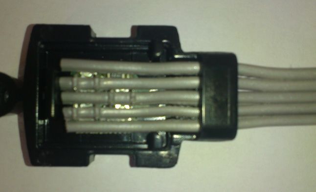
The ArcPix is produced in a standard pitch of 150mm or 300mm, but it can be customized, but the 150mm pitch
is the minimal pitch with reference to the service works.

1. Fasten the ArcPix modules on the mounting surface. Every ArcPix has an identification label with arrow on
the bottom side. When you make your installation, keep the same orientation of the ArcPix lines to ensure
the same light characteristic of each line.

2. Connect the ArcPix modules to the ArcPixel Power-CE.
  See the ArcPixel Power-CE user manual for detail description.

Max. length betwen the ArcPixel Power-CE and the last ArcPix module in a daisy chain of ArcPixes is 100 m.
 Max. number of the ArcPix modules connected to the one output of the ArcPix Power-CE is 100.

The pixels order is set at their production and cannot be changed. The first ArcPix in the daisy chain of ArcPixes
connected to the output 1 of the driver has DMX addresses 1-3 (1-red pixel, 2-green pixel, 3-blue pixel). The
last ArcPix in the daisy chain has to be ended with the termination box.

                                                        2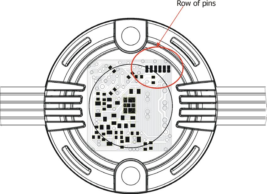
To install the termination box

1. Separate cores in length cca 40mm on the end of the 5-wire flat cable (1).

2. Insert the 5-wire flat cable (1) through the bushing (2) into the base of the termination box (3) until it touches
the partition (4) in the termination box (3) and align the cores into cutting edges.

 3. Put the cover (5) to the base (3) and press both parts (3) and (5) together until both plastic catches (6) snap
into slots (7) in the base of the termination box (3). For pressing use suitable pliers with flat jaws.

4. The hole (8) in the housing of the the termination box serves for screwing to the mounting surface.

3. Technical specifications
LED device: 					                1W RGB multi-chip
Max. current : 					             17 mA (3 channels together)
Maximum power consumption: 			   0.8 W/48V
Compatible power supply: 			     ArcPixel Power-CE
Typical Lumen maintenance: 			   50000+ hours L50@ 50°C
Cooling system: 				             convection
Beam angle:					                 126°x 133°(at half beam)
Ambient operating temp.range:			 -20°C/+50°C
Control electronics:				         Internal chip protection against overheating
Design:
						Base: plastic ABS
						                           Dome: frosted polycarbonate
Weight:						                    0.2 kg
Mounting:					                   via 2 holes in base
Protection factor:				           IP 67
IK rating:					                  IK09
Data cable:					                 5 wire flat cable Coast Wire & Plastic tech.

                                                         3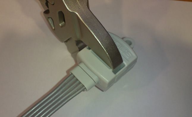
Dimensions (mm):

Termination box ArcPix

Connection box ArcPix

Accessories
(P/N 10062551) Termination Box ArcPix*
(P/N 1305 1312) Ferrite CSA19/9.4/29-4S60-EN (for ArcPix-CE) *
(P/N 10062550) Connection Box ArcPix (for changing faulty ArcPix)*
* quantity depends on size of installation (see the ArcPix Power user manual)

                                                     4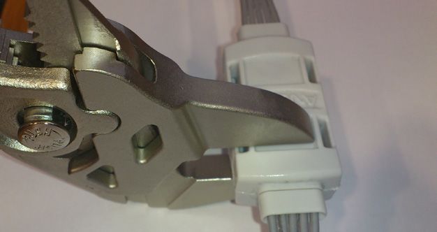
5. Replacing the ArcPix
In case that some ArcPix in a chain of ArcPixes is faulty, cut it off and use the new ArcPix and two connection
boxes to repair faulty pixel in the ArcPix chain.
1. Unscrew the faulty ArcPix and both adjacent ArcPixes.
2. Cut away the faulty ArcPix (carefully check the length of the new ArcPix cable),
3. Separate cores in length cca 40mm on the end of the 5-wire flat cable (1).
4. Insert the 5-wire flat cable (1) from old and new ArcPix through the bushing (2) into the base of the connection
box (3) until it touches two distance pins (4) in the termination box (3) and align the cores into cutting edges.
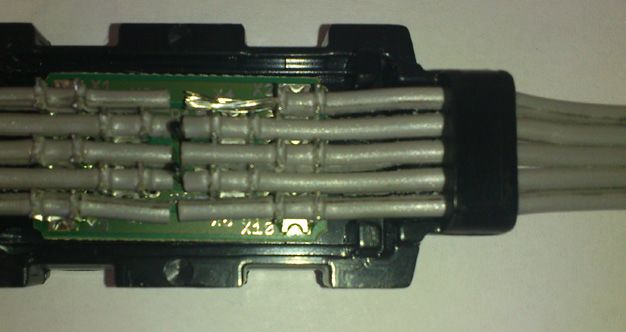
Check the position orientation of the new ArcPix before connecting it into connection boxes.
Point of orientation is the row of pins on the ArcPix´s PCB:
To keep the same light characteristic of
the new ArcPix as the rest of ArcPixes,
the position of the row of pins has to corre-
sponds with the pin position on adjacent
ArcPix (es).
5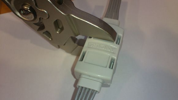
Row of pins has to be on the same side

5. Repeat step 4 for the second end of the ArcPix cable.

6. Put the cover (5) to the base (3) and press both parts (3) and (5) together until four plastic catches (6) snap
into slots (7) in the base of the termination box (3). For pressing use suitable pliers with flat jaws. Press on two
pressing points as shown on photos below.

7. Screw ArcPixes back to the surface.

Version 1.4
September 1, 2017
Specifications are subject to change without notice.

                                                         6
7
You can also read