USER MANUAL
PHACON LUMBAR SPINE TRAINER
←
→
Page content transcription
If your browser does not render page correctly, please read the page content below

USER MANUAL PHACON LUMBAR SPINE TRAINER
DISCOVER THE INTRODUCTION
IN OUR PHACON TRAINER:
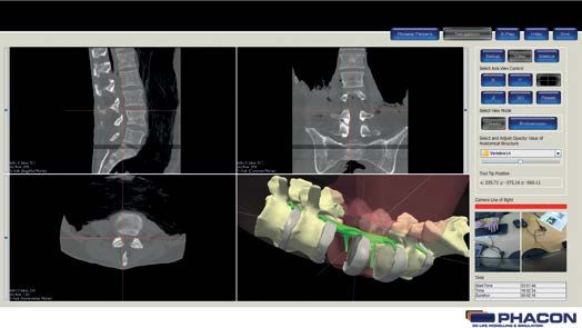
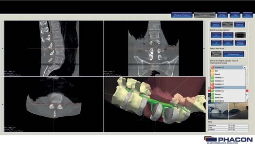
TABLE OF CONTENTS
7     IMPORTANT INFORMATION

8     BUTTONS

9     OPERATE THE TRAINER

     10     SET UP THE OPERATION-AREA

     10     SET UP THE NOTEBOOK

     11     ENTER THE APPLICATION

     13     PERFORM SETUP FOR NAVIGATION

     14     PERFORM PATIENT CALIBRATION / REGISTRATION

     15     PERFORM TOOL CALIBRATION

     17     SELECT A VIEW DURING SIMULATION

     18     SELECT THE AXIS VIEW

     18     ADJUST THE QUALITY OR PERSPECTIVE OF THE X, Y, AND Z WINDOWPANE DISPLAY

     19     ADJUST THE PERSPECTIVE OF THE 3-D WINDOWPANE DISPLAY

     20     VIRTUALLY EXTEND THE TOOL

     21     SELECT THE LIVE CAM VIEW

     22     ADJUST THE OPACITY VALUE OF AN ANATOMICAL STRUCTURE

     23     X-RAY FUNCTION

     24     DETECTION OF THE SPINAL CORD

27    TROUBLESHOOTING

29    ERROR MESSAGES

30    PRODUCT WARRANTIES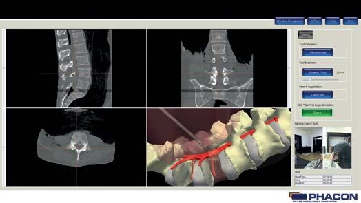
IMPORTANT INFORMATION
The words WARNING, CAUTION, and NOTE have special meaning and              DESCRIPTION 				REF
should be reviewed.                                                          - 1 notebook carry case			             [RE-00007]
WARNING: 		           Disregarding WARNING information may compromise
                                                                             - 1 USB foot switch				                [RE-00034]
		                    the safety of the patient and/or healthcare 		         - 1 Lumbar spine patient “Schumann”		  [SP-da]
		                    staff and may result in injury.                        - 1 Live-camera with ball-head		       [RE-0005]
CAUTION: 		           Disregarding CAUTION information may compromise
                                                                             - 1 calibration tool - prone			        [SP-do]
		                    product reliability and may result in damage.          - 1 calibration tool - lateral left		  [SP-dp]
                                                                             - 1 calibration tool - lateral right		 [SP-dq]
NOTE: 		 NOTE information supplements and/or clarifies
		procedural information.

		                    A triangle with an exclamation point alerts the
                                                                           NOTE: If you need more information or a complete list of accessory in-
		                    healthcare professional to read and understand       formation, contact your PHACON sales representative at +49 (0)341 47
		    !               the accompanying instructions, especially the 		     83 97 32.
		                    operating, maintenance and safety information.

                                                                           DESCRIPTION
INTENDED USE
                                                                           The PHACON Lumbar Spine Trainer is a modular system.
The PHACON Trainer is intended to be used by healthcare professionals      This trainer consists of a body model connected to a laptop computer
for education and training purposes only. The trainer allows surgical      configured with special training system software. The body model is
residents and other healthcare professionals to use actual surgical in-    designed to receive a disposable lumbar spine insert and the suitable
struments on three dimensional (3-D) anatomical models in a simulat-       torso with skin and muscle. The inserts are intended to be used for a
ed surgical setting.                                                       single surgical simulation and discarded after use. The trainer provides
                                                                           visual and tactile feedback through the laptop computer’s graphical
The PHACON Trainer and PHACON Patient can only be used in the man-         user interface (GUI) and the use of real surgical instruments.
ner described in the manual, otherwise serious personal injury may
result.                                                                    The body model is also equipped with a navigation camera. The cam-
                                                                           era used in combination with the navigation feature provides the ca-
If you are not sure whether parts are damaged or faulty, or if you have    pability to monitor the tip location of a pointer or surgical instrument.
any questions regarding the use, please contact PHACON Support
(Phone: +49 (0)341 47 83 97 32 or support@phacon.de) in immedi-            Through the use of navigation the trainer is able to detect whether the
ately.                                                                     surgical instrument has made contact with a critical anatomical risk
                                                                           structure or is in a critical area. Then a visual and audible signal is pro-
                                                                           vided during the simulation.
USER SAFETY
                                                                           The training system software will record the duration of the training
  !       WARNINGS:                                                        simulation, the type of risk structure injured, and the number of risk
                                                                           structures injured. After the training simulation, this information may
• Only trained and experienced healthcare professionals should use         be viewed and statistically evaluated.
this equipment. Before using any system component, or any compo-
nent compatible with this trainer, read and understand the instruc-
tions. Pay special attention to WARNING information. Become familiar       OTHER GENERAL WARNINGS
with the trainer components prior to use.
• Upon initial receipt and before each use, operate the equipment and      Please put the trainer and laptop on a firm surface that can not tilt.
inspect each component for damage. DO NOT use any component if             Do not place the laptop with its power cable directly to the PHACON
damage is apparent. See the Periodic Maintenance section.                  assistant with his skull and PHACON patient. Water injection risk!
NOTE: If you need more information:
Phone: +49 (0)341 47 83 97 32                                              If you find that the insulation on the cables is loose, please replace it
Mail: support@phacon.de                                                    and do not use any damaged parts.

                                                                           Always use your surgical instruments according to the intended use of
ACCESSORY INFORMATION                                                      the manufacturer.

  !       WARNINGS:                                                        Cases and packaging

• Use only PHACON-approved components and accessories, unless                !    WARNINGS:
otherwise specified. DO NOT modify any component or accessory.
                                                                           The suitcase and the packaging foils are not toys and not suitable for
DESCRIPTION 				REF                                                        children. There is a risk of suffocation!
 • PHACON Lumbar Spine Trainer “Schumann”      [S-00080-C]                 The packaging material is not suitable for eating.
  - 1 body					                                [RE-00077]
                                                                           Packaging waste is not to be disposed of via normal household waste.
  - 1 torso with skin an muscle			             [SP-dc-flesh]               Please think about your environment.
  - 1 navigation camera 			                    [RE-00019]
  - 1 manual 				                              [ZS-00013]                  There is a risk of tripping due to loose cables.
                                                                           There is a risk of strangulation due to cables.
  - 1 instrument tracker set for Spine surgery [RE-00017]
  - 1 notebook with PHACON simulation software [RE-00011]                  Please do not use any liquid food or drink during use.
  - 1 USB 3.0 hub 				                         [RE-00013]
  - 1 computer mouse 			                       [RE-00012]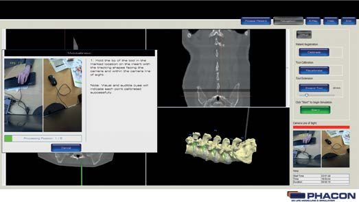
3D LIFE MODELING
                                                                                           TION
                                                                                              & SIMULA

           BUTTONS
        Buttons
        Buttons

         Button      Definition                                    Button        Definition
                     Access the MAIN MENU screen to view                          Close and exit the program.
                     major menu options.

                     Access the SIMULATION screen to begin                        End the SIMULATION or training
                     a training session.                                          session.

                     Access the RESULTS screen to view and                        Access the HELP dialog box to view
                     compare the training session data.                           instructions for use information.

                     Access the ABOUT dialog box to view                          Access the VIEW panel to select or
                     hardware and software information.                           modify a screen view or perspective.

                                                                                  Access the STATUS panel to view the
                     Accept inputs, changes or selections                         number of injured risk structures during
                     and return to the previous screen.                           a training session.

                     Reject inputs, changes or selections and                     Access the coronal view of the CT
                     return to the previous screen.                               data as a full screen display.

                     Access the CREATE NEW USER dialog
                     box to create a new user profile, user                       Access the coronal view of the CT
                     name and password.                                           data as a full screen display.

                     Access the SETUP panel to perform                            Access the transversal view of the
                     calibration of an instrument or patient.                     CT data as a full screen display.

                     Initiate the calibration of instruments or                   Access the 3-D view of the Patient and
                     patient from the SETUP panel.                                as a full screen display.

                     Select the factory default calibration set-
                     tings programmed for the instrument or                       Return to the default 4-windowpane
                     Patient.                                                     screen view.

                     Begin a SIMULATION or training session
                     from the SETUP panel.                                        View a navigated instrument without the
                                                                                  virtual camera option.

                     Continue a SIMULATION or training
                     session from the SETUP panel.                                Rotates/Flips the 3D model and X-Ray
                                                                                  images of the patient by 180°

                     Access and view the training session                         Enables/Disables the navigation. If the
                                                                                  X-Ray-View is enabled, enabling the
                     results in a graphical format.
                                                                                  navigation will switch the view to the
                                                                                  default CT/3D view.

                     Access and view the training session                         Disables the navigation and switches the view to
                     results in a tabular format.                                 the X-Ray-View of the patient. Every click on
                                                                                  X-Ray creates a new snapshot of the current
                                                                                  position of the tool within the X-Ray images.
                     Virtual extension of the instrument.

                     Open a tutorial.

                     Add a graph in the result screen.

                     Select or toggle the language for the
                     software (German/ English) .

                     Reset the default settings for brightness,
                     contrast and slice position in the 4
                     windowpane in the simulation mode.

                                                                                                                                3
    8
4
PHACON
  3D LIFE MODELING & SIMULATION

      To operateOPERATE
                 the System THE TRAINER
                                                                                     To operate the sy
    To enter the application
To enter the application
    1. Double click on the “PHACON Training System” icon located on the laptop computer
    desktop to log into the training program.
1.        Double click on the „PHACON Training System“ icon located on the laptop computer desktop to log int
          training program (Fig. 2).

Fig.: 2

2.        Enter your unique user name and password. NOTE: If you are a new user, click on the CREATE NEW
          USER button. A CREATE NEW USER dialog box will appear. Enter the required information into each
          and then click OK.

3.        After a successful LOGIN, an existing group can be selected in the GROUP drop-down list (Fig. 3 pag
          Select an existing group or enter a new group name into the NEW GROUP NAME field, then click OK.

4.        From the MAIN MENU screen, click the SIMULATION button (Fig. 3 page 5).

                                                                                                      9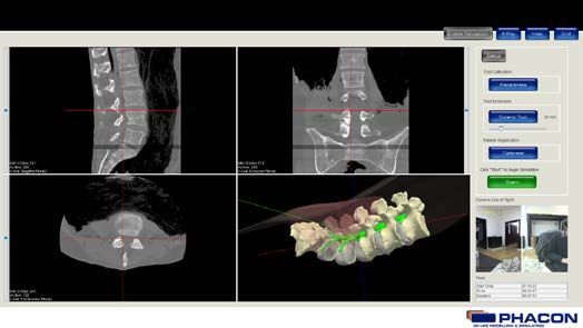
OPERATE THE TRAINER

     SET UP THE OPERATION-AREA
     • Place the torso in desired position.
     • Mount the spine in the torso.
     • Insert the navigation camera
     • Position the live-camera.

     SET UP THE NOTEBOOK
     • Connect navigation cameras directly to the two left USB ports on the notebook.
     • Connect the mouse and the live-camera via USB splitter to the notebook on the right side.

10
ENTER THE APPLICATION
• Double click on the “PHACON Trainer” icon located on the notebook
desktop to log into the training program.
• Type in your user name and password.
If you do not have an account you can create one or log in as guest.
11• To create a new user, fill in your first and last name. Define a username, type in a password
and re-type your password. The other fields are optional.
• From the MAIN MENU screen, click the SIMULATION button.
12PERFORM SETUP FOR NAVIGATION
• Click on the SETUP button to perform patient and instrument calibration for optimal
navigation results.
TOOL DETECTION INDICATOR
green = if an instrument is detected.
yellow = if multiple instruments are detected.
red = if no instrument is detected.
13PERFORM PATIENT CALIBRATION / REGISTRATION
• Put the appropriate calibration aid on the spine (each calibration aid lies on the
vertebrae 2, 3, 4 - on the facet joint and the dorsal process).
• Click the CALIBRATE button.
NOTE
The spine patient calibration is performed to align the spine coordinate system with the
coordinate system of the pointer or your tool.
The five calibration points are visible on the Spine Patient and within the 3-D windowpane
during calibration. Progress bar provided in the Patient Calibration dialog window as visual
feedback during the calibration process.
An INFORMATION MESSAGE pop-up will appear to indicate the successful completion of the
calibration procedure. Click on the START/ RESUME button to begin or continue the simula-
tion, respectively, if desired.
14PERFORM TOOL CALIBRATION
• Attach the appropriate tracker firmly to the instrument.
• Put each instrument into the correct hole in the calibration aid.
• Click on the button “RECALIBRATE” under Tool Calibration.
15NOTE
• Repeat the process for each instrument separately by putting it in the right hole
(Pointer in “RE”, Working Tube in “WT”, Reamer in “RE”, Guiding Rod in “GR”,
Needle in “NE”).
• Each instrument must be calibrated before the instrument may be used within
the navigation.
• The pattern of the calibration aid must be covered while calibrating the instuments
• To apply navigation, make sure the appropriate tracker is installed on your tool.
ALWAYS make sure the round shapes of the pointer or instrument tracker are aligned and
visible to the navigation camera’s line of sight during any calibration.
The dialog box is showing which instrument will be calibrated. To calibrate another instru-
ment, the selected tool can be exchanged during the shown time in seconds. The software
automatically detects the current instrument in use. The tracker must not be moved on the
instrument after the calibration.
16SELECT A VIEW DURING SIMULATION
From the panel menu bar, click on the VIEW button to access the VIEW panel options including
AXIS VIEW CONTROL, VIEW MODE, and the OPACITY VALUE of an ANATOMICAL STRUCTURE.
NOTE
The hair cross is visible within each windowpane represent the location of the pointer, or instru-
ment tip when using the navigation.
17SELECT THE AXIS VIEW
• Click on the X, Y, Z, or 3-D button to access the X, Y, Z, or 3-D surface windowpane in a full
screen view.
• Click on the four-quadrant windowpane button to return to the default fourquadrant screen view.
• Click on the RESET button to return the X, Y, Z and 3-D view, if modified, to their original default
settings.
ADJUST THE QUALITY OR PERSPECTIVE OF THE X, Y, AND Z WINDOWPANE DISPLAY
• To adjust the brightness click into the desired windowpane, hold down the left mouse button
and move the mouse up and down.
• To adjust the contrast click into the desired windowpane, hold down the left mouse button and
move the mouse left and right. The middle mouse button may also be used.
• To pan, click on the desired windowpane, hold down the shift key and left mouse button, and
move the mouse up and down or left and right. The middle mouse button may also be used.
• When using the navigation, the CT image slice is selected automatically based on the tip
location of the pointer, or manual instrument. To view different slices of a specific X, Y, or Z
perspective, move the slider of the appropriate windowpane.
18ADJUST THE PERSPECTIVE OF THE 3-D WINDOWPANE DISPLAY
To rotate, click on the 3-D windowpane, hold down the left mouse button and move the
mouse down. The mouse wheel may also be used.
NOTE
The ENDOSCOPIC view button allows you to use a navigated tool as a virtual endoscope.
19VIRTUALLY EXTEND THE TOOL
NOTE
Tool extension can be performed to show the tool path during the simulation.
To virtually extend the tool in the 3-D windowpane, click on the EXTENDED TOOL button and
move the slider to variable extend. The virtual tool extension is shown as a red line in the
3-D windowpane.
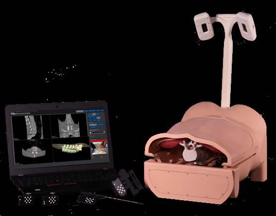
20SELECT THE LIVE-CAM VIEW
By clicking the “Live-Cam” button, you will get into the live view mode. A separate and adjust-
able window occurs, which is showing the live view of your area of interest. Therefore you have
to fix the camera in the desired position. The camera is freely positionble and inclinable by
using the ball-head.
NOTE
You can freely adjust the position and size of the “Live-View” window on your screen (including
on a different monitor if you are running multiple monitors).
The window settings will be saved until the end of your session.
21ADJUST THE OPACITY VALUE OF AN ANATOMICAL STRUCTURE
The opacity of a specific anatomical structure may be changed to provide better visualization
within and behind the Patient.
• Click on the drop-down list and select the desired anatomical structure.
• Move the slider to change the opacity of the selected structure or click on the square button
next to the selected structure to change opacity in steps „off“ (red), 25 % (orange),
75 % (yellow), „on“ (green).
NOTE
Transparencies will be saved and will be reloaded when restarted.
At the end of the list for anatomical structures there is a reset button that will put all
structures back to full visible.
22X-RAY FUNCTION
NOTE
The software has a virtual X-ray function that enables the user to create an X-ray image of the
exact location of the instrument in relation to the spine structure.
To operate the X-ray function use the right foot-step. To get back to the regular view of the
navigation use the left foot switch. If you press the right foot-step again in X-ray view a new
shot is taken.
NOTE
You can create the X-ray image also by pressing the button F6 on your keyboard or by pressing
the X-RAY button located within the software. To switch back to the navigation press F5 on your
keyboard or click on the button NAVIGATION.
NOTE
You can adjust the contrast of the X-ray image by holding the left mouse button and moving the
mouse up and down on the image.
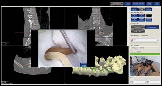
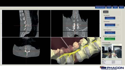
23DETECTION OF THE SPINAL CORD
NOTE
The software works with a detection function. When the instrument gets close to the spinal
cord an acoustic signal occurs. The closer you get to the spinal cord the more rapid the signal
appears.
Besides the acoustic signal, the spinal cord changes color from green to red.
NOTE
The green color means there is a safe distance to the spinal cord.
24DETECTION OF THE SPINAL CORD
NOTE
The yellow color signals the tip of the instrument is very close to the spinal cord.
This is a dangerous distance and an injury might occur.
25DETECTION OF THE SPINAL CORD
NOTE
The red color signals an injury of the spinal cord.
26TROUBLESHOOTING
PROBLEM CAUSE ACTION
The software application locks up. The application is experiencing an Press the CTRL/ALT/Delete buttons simultane-
internal malfunction. ously to perform a soft reboot. Press the ON/
OFF button to perform a hard reboot.
The navigation system is not functioning The camera lens is covered with debris. Clean the camera lens.
or is not functioning properly.
An unobstructed line-of-sight does not Make sure the line-of-sight between the
exist between the navigation camera navigation camera lens and the tracker is
lens and the tracker. unobstructed.
An other additional tracker is in the Remove the additional tracker from the
line-of-sight of the camera. navigation camera line of sight.
The navigation system is not accurate The pointer, drill, or instrument is out of Recalibrate the pointer, drill, or instru-
based on visual indications. calibration. ment. See the To Perform Tool Calibration
section.
The Patient is out of calibration. Recalibrate the Patient.
The slice selection slider bar does not A tracker is within the navigation Remove the tracker from the navigation
work. camera line of sight. camera line of sight.
The instrument does not appear in the The pattern on the instrument tracker is not Hold the tracker on the instrument into
software. in the line-of-sight of the camera. the line-of-sight of the camera, while the
pattern on top of the tracker is facing to
the camera.
The camera does not detect the tracker The detection of the tracker can be Make sure the light shining on the
on the instrument, although the pattern disturbed by very bright light shining on tracker or camera is reduced.
is facing to the camera. the camera or on the pattern of the
tracker.
The virtual 3-D model does not appear in During the endoscopic mode: Remove the additional instrument tracker
the 3-D-view. An other additional instrument tracker from the line-of-sight of the camera.
is in the line-of-sight of the camera.
The Patient calibration is not correct. Recalibrate the Patient in the Setup
menu.
The virtual 3-D model can not be moved. The endoscopic mode is enabled. Change to the Classic mode in the view
panel options.
The virtual 3-D model has a delayed The notebook is accu driven. The power Connect the power supply.
reaction. supply is not connected.
During scrolling through the CT-images, The view mode ENDOSCOPIC is enabled. Change to the Classic mode in the view
always the same area is shown. panel options.
An instrument tracker is in the line- Remove the tracker from the line-of-sight of
of-sight of the camera in the classic the camera.
mode.
27TROUBLESHOOTING
PROBLEM CAUSE ACTION
Camera is not recognized by the Check if camera is connected directly to the
software. laptop. If connected to the USB-HUB
problems might occur.
Camera arm can not be fixed. Untight adjusting screw, repeatedly turn the
hinged bracket counter clockwise several
times. Fix again the adjusting screw.
If the navigation does not work. Please check if the navigation button is
displayed in “grey” (navigation is activated),
“blue” mean navigation is deactivated.
28ERROR MESSAGES
MESSAGE CAUSE ACTION
The entered group name already exists The entered group name is already used. Enter a new group name into the system
in the system. Please enter a unique (maximum of 150 characters).
group name.
The group name field was left empty. The required field data was not provided. CEnter a group name (maximum of 150
Please enter a unique group name. characters).
A maximum of 150 characters is allowed. The entered group name consists of Enter a group name with a maximum of
more than 150 characters. 150 characters.
The LOGIN password or user name The LOGIN password or user name Enter correct LOGIN password or user
is/are incorrect. Please try again. is/are incorrect. name. Pay attention to case sensitivity.
The calibration was not successful. The instrument or patient calibration Recalibrate the instrument or patient or
failed. use the classic.
No camera found. The camera is not connected to the Make sure the camera is connected to
notebook. the notebook and click on TEST
CONNECTION.
In the setup menu: The camera is not connected to the Make sure the camera is connected to
No camera found. notebook. the notebook and click on TEST CONNECTION.
STORAGE AND HANDLING
Store the equipment within the specified environmental condition value(s) throughout its useful life. See the
Specifications section. To ensure the longevity, performance and safety of this equipment, use the original
packaging materials when transporting this equipment.
RECYCLING
Follow the current local regulations governing environmental protection to recycle or dispose of electrical
equipment at the end of its useful life.
SUPPORT
PHACON GmbH Tel.: + 49 (0)3 41 47 83 97 35
Druckereistr. 11 e-mail: support@phacon.de
04159 Leipzig
Germany www.phacon.de
29PRODUCT WARRANTIES
PHACON END USER WARRANTIES
PHACON Surgical Training Hardware, Instruments and Disposables (collectively, the “Products”) are
warranted to the original purchaser for a period of one year from the date of purchase. Products are
warranted to be free from defects in material and workmanship. The foregoing warranty covers parts,
labor, and travel if maintained and operated in accordance with manufacturer’s instructions for use.
Abnormal wear and tear or damage caused by misuse or by failure to perform normal and routine
maintenance as set out in the User Manual, or as demonstrated by an authorized PHACON or PHACON
designee’s representative, is not covered by this warranty. In order to ensure safe operation of the
Products, only PHACON accessories should be used. PHACON reserves the right to invalidate product
warranties if Products are used with accessories not manufactured by PHACON or if repairs are performed
by any party other than authorized PHACON repair personnel.
Except as set forth above, phacon makes no warranties with respect to the products or software, express
or implied, including but not limited to, any warranties of merchantability or fitness for particular purpose.
The sole liability of PHACON in the event of a breach of the above warranties is the obligation to repair
or replace the products as provided above.
In no event shall PHACON be liable for any damages resulting from or related to defects in the product
or software, including, but not limited to, damages resulting from a loss of data or from a system or
hardware non-compatibility or a system “crash” resulting from the use of the software.
In no event shall PHACON be liable for any indirect, special or consequential damages, lost profits or
lost business information arising out of or related to the product or software even if PHACON has been
advised of the possibility thereof.
30CE and FCC Declaration
CE and
CE and FCC
FCCDeclaration
Declaration
Manufactureres declaration / Herstellererklärung
Manufacturers declaration / Herstellererklärung
We declare that the following named device conforms with the requirements of the
below marked EEC Directives. If the device is mounted in a machine the operation of
that machine is forbidden until the machine itself conforms with the requirements of
Safety of Machinery Directive 89/392/EEC with Appendix.
We declare that the following named device conforma with the requirements of the
below marked EEC Directives. If the device is mounted in a machine the operation of
Hiermitthat
erklären
machinewir, dass dasuntil
is forbidden nachfolgend
the machinebezeichnete
itself conformsGerät denrequirements
with the Bestimmungen
of
Safety of Machinery Directive 89/392/EEC with Appendix.
der unten markierten EG-Richtlinien entspricht. Wird es in eine andere Maschine
eingebaut, soerklären
Hiermit ist die wir,
Inbetriebnahme solange
dass das nachfolgend untersagt,Gerät
bezeichnete bis festgestellt wurde, dass
den Bestimmungen
die Maschine
der unteninmarkierten
die das nachfolgend
EG-Richtlinienbezeichnete Gerät
entspricht. Wird es ineingebaut
eine anderewerden soll, den
Maschine
eingebaut, so ist die Inbetriebnahme solange untersagt, bis festgestellt
Bestimmungen der EG-Maschinenrichtlinie 89/392/EWG mit Anlage entspricht. wurde, dass
die Maschine in die für das nachfolgend bezeichnete Gerät eingebaut werden soll, den
Bestimmungen der EG- Maschinenrichtlinie 89/392/EWG mit Anlage entspricht.
Denomination: Simulations system for lumbar spine surgery, Lumbar Spine Trainer
Bezeichnung: Simulations-System
Denomination: Simulation fürsurgery,
system for sinus die Wirbelsäulenchirurgie,
Sinus Trainer Lumbar Spine Trainer
Type: Lumbar Spine für die Nasenchirurgie, Sinus Trainer
Bezeichnung: Simulations-System
Type: Sinus
Typ: Wirbelsäule
Typ: Sinus
Identification number Produktnummer / Identification number: S-00082
Identification number Produktnummmer/ Identification number: S-00001
Considered EEC-directives/
Considered EEC-directives/
73/23/EEC Low voltage directive/
73/23/EEC Low voltage directive /
Berücksichtigte Richtlinien: Niederspannungsrichtlinie
Berücksichtigte Richtlinien: Niederspannungsrichtlinie
PHACON GmbH
Karl-Heine.Str. 15
PHACON
04229GmbH
Leipzig
Druckereistr. 11
04159 Leipzig
Hendrik Möckel Robert Haase
Geschäftsführer Geschäftsführer
Complies to FCC rules 1157-10-GE-10-PB001 31
CompliestotoFFC
Complies FCC rules
rules 1157-10-GE-10-PB001
1157-10-GE-10-PB001PHACON GmbH Druckereistr. 11 04159 Leipzig, Germany Tel. +49 (0) 3 41-47 83 97 32 Fax.+49 (0) 3 41-47 83 91 74 www.phacon.de
You can also read