Using Tools and Techniques to Optimize the Body Shop at Nissan, Rosslyn
←
→
Page content transcription
If your browser does not render page correctly, please read the page content below
Using Tools and Techniques to Optimize the
        Body Shop at Nissan, Rosslyn

                            By

                  Lizet Engelbrecht
                      29107394

Submitted in the partial fulfilment of the requirements for
                      the degree of

       BACHELORS OF INDUSTRIAL ENGINEERING

                          in the

 FACULTY OF ENGINEERING, BUILT ENVIRONMENT AND
            INFORMATION TECHNOLOGY

                UNIVERSITY OF PRETORIA
                     October 2012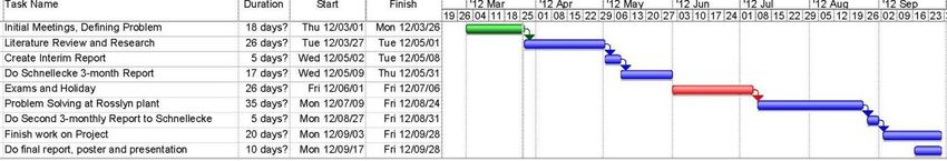
EXECUTIVE SUMMARY

Congestion is a problem not unfamiliar to any manufacturing plant. This is also the case in the
Body Shop area for the X90 project at Nissan.

Problems that arise from congestion include a longer lead time, safety hazards, over-packing,
over manufacturing, frustrated operators and an overall less productive manufacturing line.

Many tools and techniques are already in place to address congestion, such as Lean
Manufacturing, Methods Engineering, Six Sigma, Kanban pull system, TOC and other industrial
engineering concepts. Some of these will be investigated in-depth in this paper’s Literature
Review to determine ways to improve on the current manufacturing line in the Nissan Body
Shop. To understand the overhead problems, analysis will be done on specific workstations.

Journals and research done by peers in the Industrial Engineering field are reviewed to
determine the best tools for solving issues highlighted in the Problem Statement. An action plan
on how each problem will be addressed is included in the Solutions Methodology chapter of this
document.

                                                                                                  i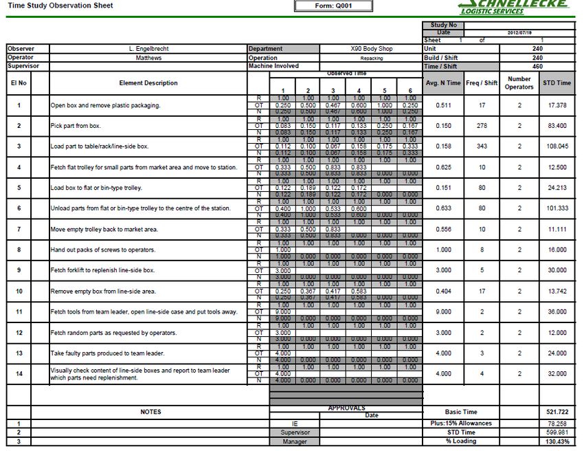
TABLE OF CONTENTS

LIST OF FIGURES AND TABLES ................................................................................................................. 1
KEY WORDS ............................................................................................................................................. 2
ABBREVIATIONS ...................................................................................................................................... 2
CHAPTER 1: INTRODUCTION ................................................................................................................... 3
   Background ......................................................................................................................................... 3
   Problem Statement ............................................................................................................................. 3
       Problems identified in the current area.......................................................................................... 4
   Project Aim.......................................................................................................................................... 5
   Deliverables......................................................................................................................................... 5
   Project Scope ...................................................................................................................................... 6
       Current facility layout ..................................................................................................................... 6
       Workstations under investigation................................................................................................... 8
   Data Analysis ....................................................................................................................................... 9
       Job/Worksite Analysis Guide .......................................................................................................... 9
       Bill of Material ............................................................................................................................... 10
       Flow Process Chart for packing operator ...................................................................................... 10
       Time Studies and Operator Utilization of current processes........................................................ 12
CHAPTER 2: LITERATURE REVIEW ......................................................................................................... 13
   Internet Journals, discussions and personal observations ............................................................... 13
       What is Lean Manufacturing? ....................................................................................................... 13
       The benefits of Lean Manufacturing ............................................................................................. 16
       “Value” with regards to Lean Manufacturing ............................................................................... 17
       “Waste” with regards to Lean Manufacturing .............................................................................. 18
       “Flow” with regards to Lean Manufacturing ................................................................................ 19
       How to start thinking in terms of “Lean Manufacturing” ............................................................. 21
       Line side storage and packaging ................................................................................................... 22
       The Body Shop .............................................................................................................................. 23
       Ergonomics in the work station .................................................................................................... 23
       Material Handling ......................................................................................................................... 24
       Facility Planning ............................................................................................................................ 25
       Material Flow System with regards to Facility Planning ............................................................... 26
       Aisle Space Specifications ............................................................................................................. 26

                                                                                                                                                        ii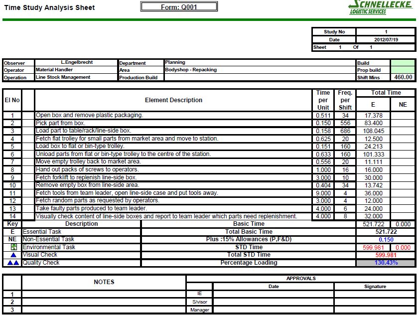
Safety considerations during Facility Planning ............................................................................. 26
       Constructing a layout plan ............................................................................................................ 27
       OSHA Act ....................................................................................................................................... 27
CHAPTER 3: SOLUTIONS METHODOLOGY............................................................................................. 28
   Appropriate Methods, Tools and Techniques .................................................................................. 28
   Action Plan ........................................................................................................................................ 29
CHAPTER 4: DEVELOPMENT OF SOLUTION........................................................................................... 30
   Proposed Solution ............................................................................................................................. 30
       The Repack Area ........................................................................................................................... 30
       The Racking ................................................................................................................................... 32
       The trolleys.................................................................................................................................... 33
       The line-side tables ....................................................................................................................... 34
   Proposed AutoCAD layouts ............................................................................................................... 35
       Proposed Layout A ........................................................................................................................ 36
       Proposed Layout B ........................................................................................................................ 37
       Proposed Layout C ........................................................................................................................ 38
   Decision Matrix ................................................................................................................................. 39
       Criteria (listed in order of importance): ........................................................................................ 39
   Budget ............................................................................................................................................... 40
       Cost of implementation ................................................................................................................ 40
CHAPTER 5: CONCLUSION ..................................................................................................................... 41
       Reduction of waste as defined by Lean principles ........................................................................ 41
       Standardization of Repack Process ............................................................................................... 41
       Implementation of a closed area for repack operations .............................................................. 42
       Ergonomics of operator using proposed process ......................................................................... 43
APPENDICES .......................................................................................................................................... 44
   Appendix A: Gantt Charts ................................................................................................................. 44
   Appendix B: Time Studies ................................................................................................................. 45
   Appendix C: Personal Budget ............................................................................................................ 47
   Appendix D: Acknowledgements ...................................................................................................... 47
References ............................................................................................................................................ 48

                                                                                                                                                         iii
LIST OF FIGURES AND TABLES
Figure 1: Problems identified .................................................................................................................. 4
Figure 2: List of Deliverables and Dates .................................................................................................. 5
Figure 3: Colours used on AutoCAD drawings ........................................................................................ 6
Figure 4: Current facility layout .............................................................................................................. 7
Figure 5: Workstations XXU12, XXU06 and XXU05 under investigation................................................. 8
Figure 6: The Ultimate Object of Lean Manufacturing. Source: (Wu, 2009) ........................................ 15
Figure 7: Process Mapping – an industry example ............................................................................... 15
Figure 8: The Benefits of Lean Manufacturing. Source: (Melton, 2005) .............................................. 16
Figure 9: Value propositions for different customer types. Source: (Melton, 2005) ........................... 17
Figure 10: Seven types of Waste. Source: (Melton, 2005) ................................................................... 18
Figure 11: Seven types of Waste........................................................................................................... 19
Figure 12: A Simple Value Stream. Source: (Melton, 2005).................................................................. 20
Figure 13: How to implement Lean Manufacturing. Source: (Melton, 2005) ...................................... 21
Figure 14: Example of racking ............................................................................................................... 22
Figure 15: Conceptual Design of a Body Shop ...................................................................................... 23
Figure 16: Anthropomorphic clearance and reach requirements in standing position. Source:
(Tompkins, 2010) .................................................................................................................................. 24
Figure 17: Space available for proposed Repack Area as drawn on AutoCAD ..................................... 31
Figure 18: Racking as designed by Schnellecke team ........................................................................... 32
Figure 19: Trolley as designed by Schnellecke team............................................................................. 33
Figure 20: Line-side tables as designed by Schnellecke team .............................................................. 34
Figure 21: Layout of the line-side tables ............................................................................................... 34
Figure 22: Proposed Layout A ............................................................................................................... 36
Figure 23: Proposed Layout B ............................................................................................................... 37
Figure 24: Proposed Layout C ............................................................................................................... 38
1KEY WORDS
Body shop
Congestion
Facility planning
Housekeeping
Lean manufacturing
Line-side storage
Material handling
Methods engineering
Nissan
Repack
Work stations
ABBREVIATIONS
BOM Bill of Material
FIFO First In First Out
JIT Just in Time
JIS Just in Sequence
m² Square Meters
OSHA Occupational Safety and Health Administration
SC Supply Chain
SLS Schnellecke Logistic Services
WIP Work In Progress
2CHAPTER 1: INTRODUCTION
Background
According to www.southafrica.info, the motor industry accounts for around 10% of South Africa’s
manufacturing exports, making it a crucial component in the country’s economy. One of the major
motor companies responsible for this figure, is Nissan.
For my final year project, I will be working alongside Schnellecke Logistic Services at the Rosslyn
plant of Nissan to improve aspects of their supply chain in which they have identified problems. The
Schnellecke office is situated inside the Nissan plant, and consists of a team of industrial engineers.
Some of the services that Schnellecke Logistics provide to Nissan include:
Supply to the Paint Shop, Body Shop, Assembly Hall and Kitting Area
Line feed for various models (using techniques for mixed-model assembly lines)
Devanning containers
Receiving CKD containers and local parts
Downsizing boxes into smaller bins
Line supply via JIS, KANBAN, Milk run, KIT-supply and Sequential supply
Line layouts, design and maintenance of facilities.
The product under investigation is the X90 project (Renault Sandero (B90) and Nissan NP200 (U90)).
These models mentioned have a current worth of between R90 000 to R170 000, with almost 140
units produced every day at this Nissan plant of Rosslyn.
Problem Statement
Multiple problems in the Body Shop for the X90 project have been overlooked for a long time. Many
problems are encountered, mainly because of congestion in the area. There is currently no effective
system in place for repacking and line-feeding of parts. A summary of the problems are given in
Figure 1: Problems identified.
Congestion leads to longer lead times, safety hazards and a chaotic work space. Line-side storage of
Work In Progress should be considered as a main point of investigation and redesign. Boxes are
spread over a very limited area of space. The use of vertical height for short-term storage has not
been considered as a means of solving the problem of lacking space, even though this option holds
many benefits. The design of racking next to the assembly line should be improved on to suit the
current size and shape of parts that are stored temporarily.
The areas around the individual workstations are cluttered and concepts from Lean Manufacturing
such as good housekeeping and minimizing waste are not currently in effect. Placement of
cardboard boxes next to welding stations is a serious safety hazard in the workplace and compliance
to OSHA regulations is being questioned. Operators have to walk distances to get to smaller parts,
since only boxes of large parts are put line-side. At some workstations, operators have to bend down
to pick parts from boxes; the ergonomics of these motions should be considered and improved on.
There is currently no dedicated area allocated for repack operations.
3Problems identified in the current area
Cardboard boxes are placed next to welding stations
•a serious fire hazard
•no thermoplastic is present between work stations and boxes
•too many boxes are placed per part number - only one box per part is
necessary
Poor housekeeping
•difficult for operator to move between boxes while repacking parts
•boxes are currently not placed on exact designated areas
•boxes are placed in the forklift aisle , creating a safety hazard
Poor repack methods are used
•parts are repacked from one box to another; boxes get worn out
•parts get damaged from poor repack methods
•some parts are not repacked on a FIFO basis
Not enough line-side tables
•only some parts are repacked properly to tables
•the current tables implemented are not standardized
Small parts have to be replenished a significant amount of times
•wastes time
•could be supplied directly to line-side in stead of being repacked
•unnecessary and redundant material handling should be avoided
The repack operators are not fully utilized
•these operators could be utilized in another area as well
•money is wasted as the operators are paid per hour, even for idle time
•as soon as the new repack area is implemented, the operators ahould be fully
utilized
Figure 1: Problems identified
In the Solutions Methodology chapter of this document a detailed proposal is given to address and
solve each of these problems.
4Project Aim
The aim of the project is to analyse existing methods used at the X90 Body Shop of Nissan’s plant in
Rosslyn, and offer suggestions for improvement. This includes use of Work Measurement, Work
Methods and Design, Production Engineering, Lean Manufacturing, Manufacturing Analysis and
Control and Facilities Planning to solve existing problems.
An in-depth research on the Ergonomics and Safety of this specific production area has to be done as
to ensure that existing work methods comply with safety regulations. Suggestions are made on ways
to increase throughput, create a safer working environment and ensure optimal line feeding from
the storage area to the manufacturing line where the body parts are welded together. The main
topic that will be addressed is the congestion around the workstations. The current method of
storing parts line-side will be investigated and a safe, closed area will be allocated for repack
operations. Alternative proposals will be done for facility layouts to address problems mentioned.
The problems listed in the Problem Statement will be addressed individually to ensure that this
manufacturing area produces a quality deliverable, on schedule with maximum employee
satisfaction. Cost reduction and quality improvements are done by eliminating non-value-adding
activities. These goals are reached through implementation of tools and techniques identified during
the Literature Review.
Deliverables
The deliverables for this project is a Project Proposal, an Interim Report with a thorough Literature
Review, a Draft Document, a Final Report which will be bound and become the property of the
University of Pretoria, a poster and a presentation to the Industrial Engineering department.
A three-monthly progress report is presented to the Schnellecke and Nissan team, apart from the
Interim, Draft Document and Final reports. The reports will include progress made in each part of
the project, problems encountered during the time at Nissan (in form of a Risk Report), possible
solutions, implementation procedures and any calculations made. The final report to Schnellecke
and Nissan will entail a presentation as well as a copy of the final dissertation.
Note that not all data may be published, such as raw numbers, the Bill of Material, any photos and
monetary amounts. In this case, proportions or percentages will be used as a substitute.
Deliverable Date Expected
Project Proposal (Phase 1) 27 March 2012
Interim Report 8 May 2012
First 3-monthly Report to Schnellecke End May
Presentation During June Exam period
Second 3-monthly Report to Schnellecke End August
First Draft of Document 5 September 2012
Final Document 17 October 2012
Third 3-monthly Report to Schnellecke End October
Presentation and Poster November
Figure 2: List of Deliverables and Dates
5Project Scope
The scope of the project covers the Body Shop of the X90 automobile being manufactured at the
Nissan Rosslyn plant. This includes the B90 and U90 models. The area that will be under
investigation starts at the storage area next to this body shop, where parts are repacked onto
trolleys. There are over 200 different types of parts being handled in this specific area. These parts
are moved to the manufacturing line where it is stored line-side, and then welded together to form
the frame of the vehicle. This process is also called Body-in-White assembly.
The project will include a problem definition, breaking the Body Shop area down into areas called
workstations and using tools and techniques to optimize each workstation. For implementation
purposes, only the three identified workstations will be selected for analysis to determine the best
practise to be used with due regard to the operators’ safety and job interest. This may be used as
blueprint for every other work station in the X90 Body Shop.
Aspects that will be addressed include Lean Manufacturing, JIT line feeding, operator efficiency,
reduction of materials handling and the quality of deliverables. Facility layouts will be drawn on
AutoCAD for the current as well as each proposed design.
It is important to note that although most of the manufacturing line at Nissan is a mixed-model line,
only the bodies of the Renault Sandero and Nissan NP200, called the X90 Project, are assembled in
this area of body shop and is not considered a mixed-model system.
Current facility layout
AutoCAD is used as the main tool for drawing the current layout as well as proposed layouts during
the solution development. The layout is drawn to scale and with accurate measurements, and future
additions or changes can easily be done on the drawings.
Welding station: Not for our use:
Cardboard boxes: Thermoplastic:
Cupboards, tables or trolleys: Steel columns:
Figure 3: Colours used on AutoCAD drawings
6Each yellow block demarcates a welding work station. The areas with red hatching are not for our
use and not covered in this scope. Black is used for general demarcation of the work space. Black
blocks with crosses, are steel columns and cannot be moved. The cardboard boxes are drawn in
Cyan Blue, while cupboards, tables, trolleys and racks are Dark Blue.
The yellow double lines are thermoplastic as currently present in the area. Thermoplastic is thick
sheeting hung from the roof where welding stations are placed next to marshalling areas or any area
which might be in range of welding sparks and could cause a fire hazard.
The drawing below shows the X90 Body Shop area, with the red block as our main focus. If all
suggestions made in this project are implemented successfully, the Nissan and Schnellecke team will
consider implementing the same solution to the remaining area as well (though it is not in the scope
of this project).
Figure 4: Current facility layout
7Workstations under investigation
The workstations included in the scope are station XXU12, XXU06 and XXU05. These are fast-moving
parts of various shapes and sizes.
Currently, boxes are placed line-side, sometimes two boxes per part number. The operator repacks
parts from the full box to one that is almost empty. In the case where there is not enough space next
to the line for a certain part number, this box is placed in the area across the forklift aisle (seen on
the bottom of the drawing below). For these specific parts, the operator fetches a trolley and
repacks parts from the box to the trolley, takes the trolley to the line, and repacks the part again to
the line-side box/table/rack. Material is handled unnecessarily and easily damaged.
In the current layout, boxes are repacked directly next to the line – which means that there is very
little distance moved during repack (minimizing material handling – something any floor manager
would consider as positive). To be able to repack directly next to the line means that boxes are
currently placed in the forklift aisle. This is unacceptable as it creates a hazard for material handling
equipment, operators responsible for repacking, and any other operator moving in the aisle. The
cardboard boxes next to the welding station pose safety issues.
These specific workstations have been chosen for investigation, as it poses the greatest safety risk in
the entire X90 Body Shop at the moment and has poor or no housekeeping in place.
Figure 5: Workstations XXU12, XXU06 and XXU05 under investigation
8Data Analysis
Job/Worksite Analysis Guide
A job/worksite Analysis Guide is a tool used to identify specific problems within an area, department
or worksite in the first phases of the investigation. This Guide is conducted on the operator in the
X90 Body Shop area that is responsible for repacking the line-side boxes when empty.
The questions relate to material handling and workplace activities. The repack operator, his tasks,
the workplace and surrounding working environment are observed closely.
Job/Worksite Analysis Guide
Job/Worksite: X90 Body Shop Analyst: Lizet Engelbrecht Date: July 2012
Description: Analysis of repacker in the X90 Body Shop area
Worker Factors
Name: Matthews Age: 22 Gender: M Height: 1.6m Weight: 65 kg
Motivation: Medium Job satisfaction: Medium
Education level: High School Fitness level: Medium
Personal protective equipment: Safety Glasses Hard Hat Earplugs Safety Shoes Gloves Other
Task Factors Refer to
What happens? How do parts flow in/out? Flow Process Chart
Repacker walks through area and replenishes almost-
empty boxes at line-side
What kinds of motion are involved? Principles of Motion Economy
Walking, lifting, grasping, placing
Are there any jigs/fixtures? Automation? Yes – Manual
Packing Stillages
Are any tools being used? Tool Evaluation Checklist
NT cutter, crow bar
Is the workplace laid out well? Any long reaches? Workstation Evaluation Checklist
No, a lot of walking, long distances
Are there awkward finger/wrist motions? No CTD Risk Index
Is there any lifting? NIOSH Lifting Analysis
Yes, larger and uncomfortable parts
Is the worker fatigued? Physical workload? Work-rest allowances
Some fatigue from walking and lifting
Is there any decision-making or mental workload? No
What is the % workload? Time Studies
130% for two workers, approx. 65% each
Work Environment Factors Work Environment Checklist
Is illumination acceptable? Is there glare? IESNA Recommended Values
Lighting is acceptable to requirements of task; welding
operations require for safety glasses in area
Are noise levels acceptable? OSHA Levels
No, necessary to wear earplugs
Is there heat stress? Some WBGT
Is there vibration? No ISO Standards
Administrative Factors
Is there job rotation? Job enlargement? Remarks:
Yes, every half day repackers rotate between two jobs
Is training or work hardening provided? Yes
9Bill of Material
The Bill of Material (BOM) is a document that contains the part number and description of the parts
in workstations XXU12, XXU06 and XXU05 – the three workstations under investigation. It is
important that the part numbers in the BOM correlates with the part numbers indicated on the
AutoCAD drawings (as seen in the Problem Scope and Solutions Methodology).
This BOM has been obtained from the Nissan system for the duration of this project, but may not be
published in the final document because of confidentiality requirements as agreed upon.
Flow Process Chart for packing operator
The Flow Process Chart is valuable in recording each task finished by the observed operator. The
operator who does the repacking for the X90 Body Shop area was followed and observed for a full
working day to establish the elements of each task. The Flow Process Charts is also an indicator of
nonproduction hidden costs such as distances travelled, delays and temporary storage.
ASME standard symbols used:
Operation
Transport
D Delay
Storage
Inspection
The station number, part number and description of each element are given. A time study is done
for each element, and the frequency that the specific part is repacked is given by the operator. An
important factor to record is the distance a part is moved by the operator (where applicable). The
estimated size of each part is indicated, and comments are made on whether the part is heavy and
uncomfortable for the operator to handle.
1011
The Flow Process Chart indicates that certain parts are heavy and uncomfortable for the operator to
handle. These parts require specific attention during solution development. Parts being moved more
than 3m should also be considered as elements that have a significant effect on the operator’s time
utilization.
It is clear that the repacking of small parts have a high frequency, is redundant and it is suggested
that these parts are to be supplied directly to the line by the supplier (and not handled by the
operator). This will reduce material handling on these parts, and reduce wasted time by the
operator.
Time Studies and Operator Utilization of current processes
A time study was conducted for each element of each task that the repack operator is responsible
for in one work day. These elements are combined to conduct an overall time study. The final goal of
the time study is to determine the percentage loading of a single operator.
The X90 body shop area under investigation currently uses two operators responsible for all the
repack activities. These operators have exactly the same flow of processes throughout the day – thus
a combined time study is conducted, and the percentage loading is divided by two afterwards to give
an indication of how efficiently these operators use their time throughout the day.
A percentage workload of 80%-90% is expected from an operator who does hard labour. Note that a
% allowance for fatigue, restroom breaks and idle time is included in the time study.
The conducted time study indicates the following:
The percentage workload is calculated at 130%, thus about 65% per operator. This is not
acceptable, and indicates that money is wasted on man-hours, as the operators could be
better utilized. This will not be a problem once the new layout and repack process (as seen
in the solution development) is implemented. Since the operator will now have to move
from the repack area to the line, operators will be utilized fully.
A lot of time is unnecessarily spent on repacking small parts. It is suggested that small parts
(such as screws and bolts, or any part that can easily be carried by hand) be delivered
straight to line-side pigeon-hole type racks by the suppliers, and thus not repacked by the
operators.
Time studies are included in Appendix B.
12CHAPTER 2: LITERATURE REVIEW
According to Niebel’s Methods, Standards and Work Design (Freivalds, 2009), an increase in
productivity is one of the main ways a business can attempt to expand and increase its profitability.
According to this textbook, a few of the essential tools that result in increased productivity, include
methods engineering, time study standards and work design. These are only some of the aspects
that will be covered in this literature review. Freivalds defines methods engineering as a practise for
increasing the production per unit time or decreasing the cost per unit output.
This literature review addresses various fields of interest in industrial engineering, including Lean
Manufacturing, line-side storage, Ergonomics, Materials Handling and Facility Planning.
Internet Journals, discussions and personal observations
What is Lean Manufacturing?
According to a journal on Lean Indicators and Manufacturing Strategies (Sanchez & Perez, 2001), the
attention surrounding lean production is based on indications that it improves the company’s
competitiveness by increasing productivity, while lowering lead time costs and refining the standard
of quality delivered.
A brief history of this concept is given in the article The Benefits of Lean Manufacturing (Melton T. ,
2005). Toyota is accountable for coining the phrase ‘lean logistics’ in the 1940s in Japan. The Toyota
Manufacturing System was grounded on the need to manufacture automobiles in a constant on-
going flow which did not rely on lengthy production runs to be entirely efficient; Toyota recognized
that only a small portion of the overall production time and effort actually added some value to the
final customer, the rest of the activities is considered to be wasteful.
Meanwhile, the Western world was doing the opposite of this practise; concepts such as Materials
Resource Planning (MRP) and other systems based on intricate computerized methods were being
developed. Henry Ford’s philosophy of bulk-sized assembly of standardized products with little
product changeovers was also being followed. Henry Ford based his viewpoint on mass production.
Taiichi Ohno became the father of the Lean Manufacturing methodology in the Toyota Production
system in the 1940s to 1980s. The five main tools within this ‘lean’ ideology include:
5 S’s: a method of visual housekeeping which delegated control to the shop floor.
Visual control: a way of determining performance at the ‘shop floor’ which was visual and
owned by the group of operators.
Kanban: a visual signalling system to ensure flow by letting the product be pulled through
the production line as by the end-customer requirements.
Poka yoke: a tool for ‘error-proofing’ the manufacturing process.
Single minute exchange of dies (SMED): a method to reduce length of changeovers.
During the research of this specific project, however, only some aspects of Lean Manufacturing will
be covered, such as waste, value stream mapping and flow of products. Lean is a concept that
should be drawn across an entire supply chain, but we are only focusing on one part of the SC – the
13X90 body shop. The focus will be on elimination of zero-value activities. This is the elimination of
everything that does not add value to the product in this specific area of manufacturing.
An article in the International Journal of Physical Distribution & Logistics Management (Jones, Hines,
& Rich, 1997) discussed the seven common forms of waste, as defined by Taiichi Ohno:
Waste is events and activities that are non-value-adding; it only adds to the expenses of production.
Examples of waste include the percentage of products that are not yet ordered by the customer;
time spent waiting for parts to arrive at a work station; rectification of errors; superfluous
processing; unnecessary movement of material; unnecessary transport; and additional stock at
hand. It is common to find that in a manufacturing plant less that 5 % of activities actually add value,
35 % are non-value-adding activities that are absolutely necessary and cannot be reduced and 60 %
are completely non-value-adding. It is fairly easy to identify the actions that add value, but it is much
more difficult to identify all the waste that surrounds these actions. A huge productivity
improvement lies in eliminating the 60% of non-value-adding activities.
Some of the key elements from Toyota’s tool kit are relevant to this project:
Organize the manufacturing operations so the product flows directly from one work station
to the next without interruptions. Set-up time is shortened to deliver each product daily or
weekly. Implementing preventative maintenance, occurrence of breakdowns is minimized.
Guarantee consistent performance by standardizing the optimum cycle for the work at each
station. Standardization of the repack process in the X90 Body Shop should be considered.
Ensure that operators stop immediately as they detect errors, so that it is not passed on to
the next work station. This makes it possible to detect rogue orders against historic data.
Manage the progress of the production line and eliminate irregularities using simple graphic
control devices.
Teach operators to log the irregularities found during production; this enables the manager
to conduct root cause elimination and prevent this from happening again. It also helps
remove waste from the process flow.
One of the Lean Manufacturing concepts is “Value Stream Mapping”. Under this concept, we will use
Process Activity Mapping, which consists of the following five stages:
1. The study of the flow of processes for the repack operation;
2. The identification of non-value-adding activities in the X90 area;
3. Deliberation of whether the current method of repacking parts can be rearranged into a
more efficient sequence of processes;
4. Consideration of an improved flow pattern; possibly changing the flow layout or
transportation routes using a tool such as AutoCAD;
5. Asking whether all actions that are being done are truly essential.
14Speediness and maintenance of production
Guarantee of lean quality and automation
Flexible production system
The 7 'zero' Balanced production and synchronization
ultimate objects IE work research on the spot
Production plan and logistic system
The research and development system of products
Figure 6: The Ultimate Object of Lean Manufacturing. Source: (Wu, 2009)
Figure 7: Process Mapping – an industry example
Another technique that could be borrowed from Lean Thinking is asking the questions: Why does an
activity occur, Who does the activity, on What machine is this activity done, Where, When and How.
This is called the 5WlH. The basis of this concept is to eliminate unnecessary activities, simplify
others, combine others and identify ways to change the sequence in order to reduce any waste.
15The benefits of Lean Manufacturing
Less Process
Waste
Reduced Reduced Lead-
Inventory Time
Typical Benefits
Increased
Process Less Rework
Understanding
Financial
Savings
Figure 8: The Benefits of Lean Manufacturing. Source: (Melton, 2005)
In the same journal cited previously (Melton T. , 2005), the benefits of a manufacturing line being
“lean” is discussed clearly. According to this journal, the benefits seen within the automotive
industry (see Figure 4), such as Nissan, include:
reduced inventories for the manufacturing companies;
reduced lead times for the end-customer;
overall better knowledge management;
more robust practises (minimized errors and consequently there will be less rework).
These benefits make the “lean” methodology a real and physical concept, particularly for the
manufacturing industry. Over the entire supply chain Lean Manufacturing has now been applied.
There are multiple documented case studies of the application of ‘lean thinking’ to business
processes such as project management, construction and design. Lean Manufacturing should be
applied to all facets of the supply chain.
The application of this ideology in the industry is not without problems. The two main complications
are based on human assumption: the perceived lack of palpable benefits and managers’ opinion that
their industry processes are already efficient as it is. Both assumptions can be challenged (Melton,
2004):
There are many concrete benefits related to supply chains that have implemented Lean
thinking. A lean process will not be as slow as before, e.g. the response rate to a request for
the business process will be quicker, which naturally leads to substantial financial benefits
for this business.
The assumption that a certain process is already effective enough in its current state is
usually an illusion. The implementation of Lean Manufacturing forces companies to review
the entire supply chain in which the business process functions, and this usually reveals
bottlenecks, hold-ups and areas that are not as efficient as can be.
Nissan is not under the illusion that the assembly line in the body shop is efficient in its current state.
Through discussions with industrial engineers and floor managers, it is clear that Lean Manufacturing
is a notion that could (and should) be effectively implemented in this part of the plant.
16“Value” with regards to Lean Manufacturing
The supply chain is a vehicle for delivering the product (of certain value or worth) to the end-
customer. The lean concept is applicable to Manufacturing Businesses and specified processes in
that industry. Waste can be eliminated from most steps of the production line: from the
development and design of the initial product, all the way down to the planning of the facility layout.
However, to truly apply the concept of lean thinking, all these elements have to be interconnected
within a robust supply chain and the flow of value has to be ensured. This leads to what is now called
a ‘lean enterprise’ (Lean Enterprise Research Centre, 2004).
Manufacturing processes can be greatly improved by eliminating waste. The key is to:
1. Realize the difference between waste and value in the supply chain;
2. Expand our base knowledge management;
3. See that sustainable development calls for the cooperation of the process operators as well
as the business management, and therefore a philosophy of on-going improvement toward
perfection.
Value can be defined as the worth of something compared to the price paid or asked for it. Different
customers, however, might view value differently (see figure 9 below).
Defining “value” from the customer’s point of view and identifying this value is the first step to
implementation of lean thinking in the Nissan X90 Body Shop. Without a clear understanding of
what meaning ‘value’ holds for the customer, we cannot move forward. Various examples exist of
what is meant by “value proposition”; a buyer purchasing a washing machine may value the ability
to wash their clothes at home; while others’ value may be based on the price or some special
features that the product offer. The manufacturer is challenged to develop a product portfolio based
on these value propositions.
Figure 9 gives instances of such value propositions as related to specific customer groups, their
product portfolio and potential capabilities. For customer A, development of the process they hand
over to the toll manufacturer is a value added activity; for customer B this is considered to be waste.
Customer Type Value Proposition Manufacturer Type
Robust process and product
A Major pharmaceutical Toll manufacturer of
development at fast track speed
manufacturer of drug products pharmaceutical intermediates
ensuring regulatory compliance
Correct specification, low cost
B Other manufacturer in a low
and delivered on time in the Bulk chemicals manufacturer
cost base industry
volumes specified
C The patient (via the companies High quality, safe drugs that Major pharmaceutical
who distribute the drugs) ‘work’ at an appropriate price manufacturer of drug products
Figure 9: Value propositions for different customer types. Source: (Melton, 2005)
17“Waste” with regards to Lean Manufacturing
Waste has already been defined and discussed in this Literature Study. An additional definition is
cited from a journal also viewed earlier (Melton, 2005). Any task in a production process that adds
no value or worth to the end-customer is considered waste, or “Muda”, as the Japanese calls it. In
some cases, the waste adds value to the company or is a necessary part of the process and thus
cannot be eliminated.
All waste that is not considered “necessary” to the process, should be eliminated as far as possible.
Figure 10 lists the seven main types of waste; each of which is present in the body shop area under
investigation in this project. At first, waste can be recognized with ease in the processes along the
body shop’s supply chain and early alterations or modifications can lead to vast savings for Nissan.
As the processes constantly improve, the waste reduction will be more incremental as the company
strives for a waste-free production line.
Continuous improvement is one of the main principles of implementing lean logistics. The data in
Figure 11 shows only a small part of the amount and types of waste that could be found in the
overall supply chains. It is of utmost importance to identify the root cause (the ‘real’ waste) in order
to eliminate all its repercussions.
Over
Production
Defects Waiting
Waste
Motion Transport
Over
Inventory
Processing
Figure 10: Seven types of Waste. Source: (Melton, 2005)
Walking through the X90 body shop at Nissan, it is clear that these forms of waste are present
throughout the assembly line. Some examples include:
An overproduction of parts
Unnecessary transport of material
Excessive motions during picking of parts and assembly of products
Presence of defects on parts because of poor quality in materials handling
Some parts are over-packed into boxes that stand line-side for weeks on end. The box
deteriorates, and the parts are thrown on top of one another, increasing the chances of
defectives in the batch.
18Figure 11: Seven types of Waste
“Flow” with regards to Lean Manufacturing
One of the concepts of Lean Manufacturing that is hardest to understand is “Flow” (Melton T. ,
2005). It is the notion which most clearly contradicts with large quantity manufacturing systems
(Henry Ford’s philosophy); comparing a single flow against batch and queue processes. The
business’s working capital is consumed by large warehouses which store huge amounts of inventory.
The size of these warehouses is caused by a lack of flow in our supply chain. To understand the
concept of flow the term “value stream” can be defined as the relation of tasks which finally
produces value to an end-customer. A value stream crosses all practical and organizational
boundaries.
Figure 12 demonstrates an example of a typical value stream for a toll manufacturer. The value
stream only shows the primary stages of value being added and the main teams involved (and not
the supporting activities). Flow is concerned with processes, people and culture.
19Figure 12: A Simple Value Stream. Source: (Melton, 2005)
In The Goal (Goldratt & Cox, 1993), the concepts around a value stream are discussed. The key
reasons for an absence of flow (or constraints in the supply chain) are also mentioned. Goldratt and
Cox developed some guidance to control a manufacturing line in how it is supposed to be managed.
This guidance is formed around the following concepts:
1. Throughput: the degree to which the supply chain generates money through sales (actual
sales should be used, not actual production; if a product is produced, but not sold, it is not
considered throughput). The lean philosophy of manufacturing only when the customer
‘pulls’ is supported in this idea.
2. Inventory: the monetary amount that the system used for procuring products which it has
the intention to sell.
3. Operational expense: the monetary amount spent by the system in order to convert
inventory into throughput.
The aim of that production operation is defined as ensuring a higher throughput while lowering both
operating expense and inventory. It is stated that any improvement in the system must be tested
against this idea:
Will this improvement lead to:
o An increase in the sales of products? (Has Throughput increased?)
o A reduction in raw materials and overtime? (Is Operating Expense reduced?)
o A reduction in the plant’s over-all inventory?
The final notion introduced in The Goal is that of the bottleneck - the throughput of the entire
process is determined by this single step. This also supports the philosophy of lean production
through ‘pull’ which communicates to operators that it is acceptable to halt production (when there
is no ‘pull’ from the end-customer).
‘A value stream perspective means improving the whole supply chains, not just improving some the
parts’ (Rother & Shook, 1999). It also suggests that we need to function as a supply chain, and not
necessarily as individual production units.
20How to start thinking in terms of “Lean Manufacturing”
A data-rational, organized method is necessary if the main ideologies of value, flow and waste are to
be thoroughly applied through the process supply chain. The process of implementing Lean
Manufacturing (Figure 13) is shortly described:
Document the existing process performance – how is it done at the moment.
Outline value and then eliminate waste (non-value-adding activities).
Identify unwanted effects. Find their root cause to be able to eliminate the actual problem.
Solve this problem by re-designing the process.
Determine whether value flow is now sufficient to the end-customer of the specific process.
Many methods and practises exist to support each phase of the process described above (that
support application of the philosophies). Managers that have been involved in performance
improvements are surprised that the ideologies of Lean Manufacturing can be put into action using
methods that are well-known to them and that they have used before. The difference is the fact that
they are used to guarantee that:
The process line delivers value to the end-customers;
Every task that is non-value-adding is eliminated as far as possible;
The supply chain now flows within a ‘lean’ and robust supply chain.
Step 1: • Observe current processes and look for waste/Non Value Add (NVA).
Involve the people who run these processes daily - unlock their
Collect Data knowledge.
• Using cross-functional teams start to diagnose the issues through
Step 2: data analysis , e.g. what stops the process flowing?
Analyse Data • Look for undesirable effects - incidents which you don't want to occur
but which are a part of the current process.
• Based on the data analysis a change can be designed - this usually
Step 3: involves elimination of the waste and undesirable effects. A new
Design the process can be defined. The design must encompass a sustainable
change and will usually involve the cross-functional team who have
Change collected and analysed the data.
Step 4: • The new process is put in place with appropriate training and
measures, i.e. so that the team operating the process have the ability
Make the to monitor the sustainability of the change and can make adjustments
Change as necessary.
• The new process is monitored and the benefits evaluated on an
Step 5: ongoing basis.As the team running the new process continue to collect
Measure the and analyse performance data further incremental improvements can
be made and a culture of continuous improvement based on data
Benefits rational approach is developed.
Figure 13: How to implement Lean Manufacturing. Source: (Melton, 2005)
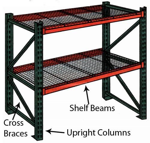
21Line side storage and packaging
In a journal article on the impact of materials feeding design (Wänström & Medbo, 2008), it is
explained that the design of component racks and choice of packaging types have a significant effect
on the performance of the assembly line. A component rack that is mobile and fairly easy to
rearrange, together with free space, makes the handling of new products or alterations of products
much easier.
Limitations that may be encountered in this area of research consist of space restrictions and
working conditions at the individual workstations. Component racks are defined as a facility with
which materials are made available and held (or temporarily stored) at assembly work stations, e.g.
a rack, stand, fixture, shelf or trolley. A component rack could be a permanently bolted EUR-pallet
rack placed next to the assembly line. The racks can be furnished with shelves and flow racks for
various shapes and sizes of containers. Gravity flow racks are only used for smaller parts.
Figure 14: Example of racking
The current practise at Nissan’s body shop is to place the pallets with the original cardboard box
right next to the workstation. In certain areas, over-packing is done; parts are manually moved from
the current container to a container that has been standing line-side for a period of time. These line-
side containers are often damaged, and parts are not replenished in a FIFO sequence. Parts at the
bottom of the box could be old and damaged.
Where large parts such as door panels are handled, the parts are repacked onto basic line-side
tables. Provision is made for certain parts that are awkwardly shaped and difficult to handle, but this
is the exception.
Designs will be done for line-side tables, racks and trolleys in the Solution Development chapter.
Each piece of material handling equipment will be standardized and designed according to
ergonomic standards. Line-side tables will be implemented for all part numbers – not exclusively
large parts. Suggestions could be made on the provision of small parts to be delivered directly to the
line. For these small parts, pigeon-hole type racks with gravity chutes may be used.
22The Body Shop
Within the car body shop of an automotive plant such as Nissan, the body-in-white is assembled
from pre-formed pieces of metal (Spieckermann, Gutenshwager, Holger, & Vos, 2000). At the Nissan
plant, these pieces of metal are produced and received locally. In the body assembly shop, up to one
hundred welding machines and various other equipment are needed to complete the body-in-white
before it is transported to the next phase of the assembly process. Manufacturers have to design a
new body shop for almost each new model to be manufactured in the plant. A typical example of
assembly flow is demonstrated in Figure 15.
Figure 15: Conceptual Design of a Body Shop
Ergonomics in the work station
Work-in-process (WIP) includes all the assembly materials in the assembly line (Cao & Zhao, 2011).
Normally, as in the Nissan Body Shop, there is one assembly done per workstation. Buffer inventory
may be stored at the workstation for multiple assemblies. Making material available to the line and
transfer of material are closely related to facility space requirements, material distribution systems,
and line operation strategies.
The design of manual work was introduced by Gilbreths through motion study and the principles of
motion economy (Freivalds, 2009). The principles of motion study have been broken down into
three basic categories:
1. The use of the human body
2. Arrangements and conditions of the workplace
3. Design of tools and equipment at the work station
These principles form the scientific basis for ergonomics and work design. Some principles of motion
economy that is applicable to the Nissan operator include:
Achieve maximum muscle strength at midrange of motion
Achieve maximum muscle strength with slow movements
Use momentum to assist the operator wherever possible
Design the jobs to optimize human strength capability
Use large muscles for tasks requiring strength
Design tasks so that most operators are able to do them
23You can also read