VALVELINKT MOBILE SOFTWARE
←
→
Page content transcription
If your browser does not render page correctly, please read the page content below
Quick Start Guide                                                          ValveLink Mobile Software Version 3.0
D103408X012                                                                                                January 2012

ValveLinkt Mobile Software
ValveLink Mobile software provides the capability to set up, calibrate, and troubleshoot HARTr
communicating FIELDVUEt DVC6200, DVC6000, and DVC2000 digital valve controllers using an Emerson
Field Communicator or PDA. See the table below for hardware requirements. Data collected in the field
using ValveLink Mobile software can be transferred to ValveLink Solo, AMS ValveLink SNAP‐ONt, ValveLink
DTM, or ValveLink PLUG-IN for PRMr applications to be analyzed and archived.

Hardware Requirements
                                  Easy Upgrade option is required to load ValveLink Mobile software (if not already
                                  preloaded) or to install updates. Requires a Bluetoothr or an IrDAr interface on
475 Field Communicator
                                  the PC to transfer valve data files. To transfer data files using Bluetooth, the 475
                                  Field Communicator must be ordered with the Bluetooth option.
                                  512 MB (minimum) or 1 GB memory card and Easy Upgrade option are required
375 Field Communicator            to load ValveLink Mobile software or install updates. Requires an IrDA interface
                                  on the PC to transfer valve data files.
                                  PDA (or smartphone) with Windows Mobiler 5 or 6.x. Requires a Bluetooth
PDA                               HART modem. Bluetooth interface or USB data cable is required on the PC to
                                  transfer valve data files.

                 475 Field Communicator              PDA with Bluetooth HART Modem

www.Fisher.com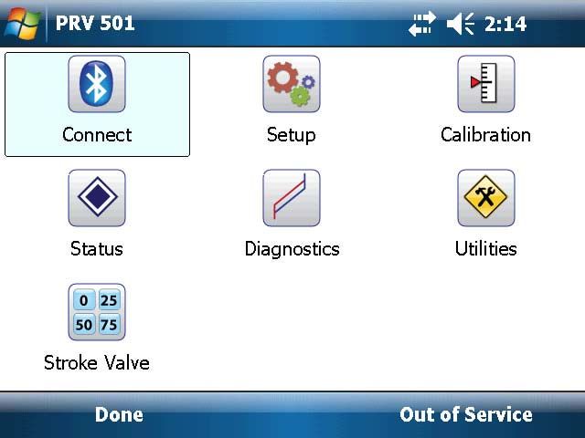
ValveLink Mobile Software Version 3.0                                              Quick Start Guide
January 2012                                                                                 D103408X012

Installation                                          manual. The default passcode for the MACTekr
                                                      Bluetooth modem is mactek.
                                                    5. Find the COM ports selection. Assign the
Field Communicator                                     modem to an Outgoing COM port (e.g.,
                                                       COM6).
Easy Upgrade is used to install ValveLink Mobile
software on Field Communicators. Refer to the       Once the modem and the mobile device are
table on the front cover for requirements.          paired you will not need to perform this
                                                    procedure again.

PDA
1. Use a USB data cable to connect your PDA to      Connecting to the Digital
   your PC.
                                                    Valve Controller
2. Establish a connection to your mobile device
   using Microsoftr ActiveSyncr 4.5 (Windowsr       The Field Communicator or Bluetooth HART
   XP) or Windows Mobile Device Center 6.1          modem may be connected to the 4-20 mA loop
   (Windows Vistar, Windows 7). These programs      wiring or directly to the digital valve controller. To
   can be downloaded from the following web         connect directly to the digital valve controller,
   site:                                            attach the clip‐on wires to the Loop + and -
                                                    terminals located in the digital valve controller
    http://www.microsoft.com/windowsphone/          terminal box.
    en-us/apps/65-downloads.aspx.
3. Run VLMobile Setup.exe from your PC to install
   ValveLink Mobile software on your mobile         Launching ValveLink Mobile
   device.                                          Software
Pairing a Bluetooth HART                            Field Communicator
Modem to your PDA                                   Select the ValveLink Mobile icon from the main
1. Turn on the Bluetooth HART modem.                menu to launch the software.
2. Turn on the Bluetooth radio on your PDA.
3. From the Wireless Manager on your PDA,
   select Bluetooth Setting and add a new device.   PDA
4. Select the Bluetooth HART modem from the         On a Windows Mobile Device, select Start >
   list and enter the HART modem passcode,          Programs > ValveLink Mobile to launch the
   which can be found in the modem instruction      software.

2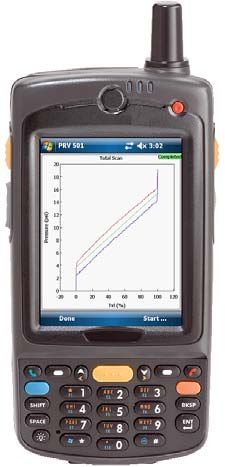
Quick Start Guide ValveLink Mobile Software Version 3.0
D103408X012 January 2012
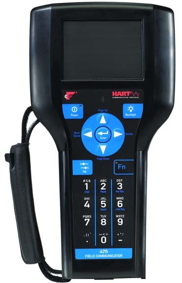
Starting ValveLink Mobile Establishing a Connection
Software
Startup Screen Home Screen
ValveLink Mobile software can be run with
Read/Write or Read Only privileges. Read/Write Field Communicator
gives you access to all functionality in ValveLink Select Connect from the home screen.
Mobile software.
Select Read Only to view device parameters, PDA
download the current instrument configuration,
or monitor device variables using Status or PD 1. Turn on the Bluetooth HART modem and the
diagnostics. You cannot change the instrument Bluetooth radio on your mobile device.
mode, run calibration or Setup Wizard when Read 2. Select Connect > Change > Bluetooth COM
Only has been selected. Port. Set the COM port as defined in the pairing
process above, e.g., COM6.
3. Select Connect.
ValveLink Mobile software will remember the last
successful connection and you will not have to set
the COM port again.
3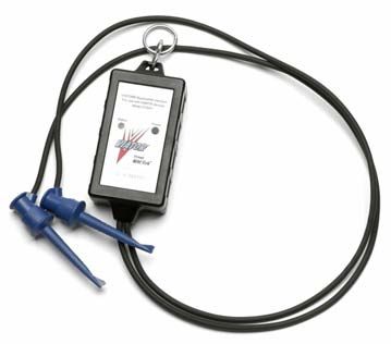
ValveLink Mobile Software Version 3.0                                                 Quick Start Guide
January 2012                                                                                      D103408X012

Navigation Tips                                         Axes may be translated by grabbing an axis scale
                                                        and sliding it to the desired position as shown in
List controls are scrolled with grab‐and‐drag input     the figure below.
from a stylus or finger as shown in the screen shot
below.

                                                                                 Secondary PD Graph

Once you find a row you want to change, you can         PD graphs can display up to four variables on two
hit the selection button (>). The selection button      graphs. The second graph can be viewed by
may not be visible if you are not connected to a        grabbing a graph anywhere except the y-axis
device. Parameters that cannot be changed will          scale and sliding the graphs up or down.
have a next to the selection button. These will
usually be displayed when the instrument mode           Graphs can be zoomed in by using a stylus to
is In Service.                                          draw a selection band around the desired area.
                                                        Tap on the screen to reset.
The command bar located at the bottom of the
screen has two soft keys. The left Done soft key is     Crosshairs can be displayed by selecting the
used to go back one screen. The right soft key          directional pad (up, down, left, right arrows)
displays instrument mode (In Service, Out of            Enter key until the coordinates appear.
Service, or Not Connected). Select this key to
change instrument mode.
Most tasks will display a green highlighted bar to
indicate that the task has completed successfully.
                                                        Other Information
For off‐line diagnostic tests, wait for the
green              highlight to appear on the
graph before moving on to the next test.                Bluetooth
                                                        Bluetooth communications are generally robust,
                                                        but the radio signal can be absorbed by water.
Graph Controls
Graphs are displayed in real time or statically after   The most likely sources of water are your hand
a test has completed. When zooming or                   and people that might be between the Bluetooth
translating graphs, data will be collected in the       radios. Some PDAs have the Bluetooth radio
background but updates to the display will be           antenna where you put your hand, which can
paused. Tap to restart display updates.                 interfere with the signal.

4
Quick Start Guide ValveLink Mobile Software Version 3.0
D103408X012 January 2012
ValveLink Mobile Software Menu Structure
CONNECT
Connect is the starting place for establishing communications with a
FIELDVUE instrument. Select connect to access the HART tag, last calibration
date, and other relevant connection information.
SETUP
Setup Wizard
Use the Setup Wizard to guide you through initial instrument setup and calibration. All
fields must be filled in before you can select Apply to download settings to the
instrument. The instrument mode must be set Out of Service before the Setup Wizard
can download parameters to the instrument.
Detailed Setup
Detailed Setup is used to to manually set instrument parameters.
Initial Setup
Fundamental instrument parameters, such as Zero Power Condition. Once
these have been established, they generally do not need to be changed.
Tuning
Parameters for tuning travel and pressure servo controllers.
Response
Parameters for configuring rate limits, input filter time constant, and
input characteristic.
Travel / Pressure Control
Parameters for configuring cutoffs, travel limits, and pressure fallback.
Alerts
Parameters for enabling alerts and setting alert thresholds. Alert states can be
viewed using Status.
Engineering Units
Use Engineering Units to set instrument units. The display of operational parameters
in ValveLink Mobile will be consistent with units configured in the instrument. 5ValveLink Mobile Software Version 3.0 Quick Start Guide
January 2012 D103408X012
Write Protection
Used to enable or disable Write Protection in the instrument. When enabled, Write
Protection prevents configuration and calibration changes to the instrument.
Save Detailed Setup
Save Detailed Setup is used to save a record of all device parameters. Saved data
can be viewed in Data Set Explorer.
Spec Sheet
Reference list detailing valve body, actuator, and trim construction. Used to
provide context for diagnostics.
CALIBRATION
Auto Travel
Auto Travel provides guided procedures for calibrating travel control and pressure
fallback.
Manual Travel
Manual Travel provides guided procedures for manually calibrating travel feedback.
Parameters for pressure fallback can be manually set in Detailed Setup.
STATUS
Monitor Tab Displays operating parameters, such as input current, travel, and
supply pressure.
Alerts Tab Summarizes instrument alert states:
Alert ON Alert not enabled (alert state is unknown)
Alert OFF Alert not read (alert state is unknown)
Device Info Tab Shows HART tag, firmware revision, device ID, last calibration date, etc.
6Quick Start Guide ValveLink Mobile Software Version 3.0
D103408X012 January 2012
DIAGNOSTICS
Total Scan
Pressure versus travel, travel versus time, and pressure versus time graphs are
available using Total Scan. This is an off-line test that must be run with the instrument
mode set Out of Service. Total Scan tests are used to estimate friction, bench set, and
seat load.
Step Response
Four preconfigured step tests are available. These are off-line tests that must be run
with the instrument mode set Out of Service.
Stroking Time - Response to target set point values of 0%, 100%, and 0%. Used to
estimate the time required to fully open and fully close a valve.
25% Step Study - Response to target set point values of 0%, 25%, 50%, 75%, 100%,
75%, 50%, 25%, and 0%. Used to check linearity.
Large Step Study - 10%, 20%, …, 80% steps from a baseline of 10%. Used to assess
stability of valves with complex accessory configurations.
Performance Step Test - Bidirectional steps with amplitudes of 0.25%, 0.5%, 1%, 2%,
5%, and 10%. Used to estimate valve dead band and dynamic response.
PD One Button - Preconfigured, on-line diagnostic tests for identifying faults. Must
be run with the instrument mode set In Service.
PD Traces - Real time traces of any device variable. Must be run with the instrument
mode set In Service. PD Traces are especially useful for tracking down limit cycles or
other unusual or inconsistent behavior.
UTILITIES
Data Set Explorer
Select Data Set Explorer to view all diagnostic data by tag. Navigating to
the data will allow it to be viewed or deleted.
7ValveLink Mobile Software Version 3.0 Quick Start Guide
January 2012 D103408X012
Wireless File Transfer
Wireless File Transfer allows you to transfer data sets or communication logs to a
desktop computer using IrDA or Bluetooth.
Wireless File Transfer combines selected tag data into one VLMobile.exp file that can
be imported into ValveLink. Most desktop Bluetooth software will guide you though
the file transfer process, however, if you have the Microsoft Bluetooth software stack
on your desktop, you will need to enable file transfer services before you can send a
file. To do this, right mouse click on the Bluetooth logo in your icon tray and select
Receive a File. If the desktop software requires a passcode, use 0000 (all zeros).
Toggle Burst Mode
Select Toggle Burst Mode to temporarily disable burst communications. This will
improve speed and reduce communication errors.
Instrument Upgrades
Instrument Level StepUp
Instrument Level StepUp is used to change the diagnostic tier in the instrument
with a device specific 15 digit code.
HART Revision
If supported, HART Revision can be used to set HART 5 or HART 7 communications
protocol in the instrument.
Instrument Family
Select DVC6000 for devices with a potentiometer feedback sensor or DVC6200 for
devices with a magnetic array feedback sensor.
About
About displays standard software identification information.
STROKE VALVE
Stroke Valve is a routine for moving a valve to 0%, 25%, 50%, 75%, and 100% lifts or by
jogging the valve up or down in 2% increments from any starting point.
Neither Emerson, Emerson Process Management, nor any of their affiliated entities assumes responsibility for the selection, use or maintenance
of any product. Responsibility for proper selection, use, and maintenance of any product remains solely with the purchaser and end user.
ValveLink, FIELDVUE, and SNAP‐ON are marks owned by one of the companies in the Emerson Process Management business division of Emerson Electric
Co. Emerson Process Management, Emerson, and the Emerson logo are trademarks and service marks of Emerson Electric Co. All other marks are the
property of their respective owners.
The contents of this publication are presented for informational purposes only, and while every effort has been made to ensure their accuracy, they are not
to be construed as warranties or guarantees, express or implied, regarding the products or services described herein or their use or applicability. All sales are
governed by our terms and conditions, which are available upon request. We reserve the right to modify or improve the designs or specifications of such
products at any time without notice.
Emerson Process Management
Marshalltown, Iowa 50158 USA
Sorocaba, 18087 Brazil
Chatham, Kent ME4 4QZ UK
Dubai, United Arab Emirates
Singapore 128461 Singapore
www.Fisher.com
E 2010, 2012 Fisher Controls International LLC. All rights reserved.
8You can also read