VEGAPULS 69 Two-wire 4 20 mA/HART - Operating Instructions - Two-wire 4 20 mA ...
←
→
Page content transcription
If your browser does not render page correctly, please read the page content below
Operating Instructions
Radar sensor for continuous level
measurement of bulk solids

VEGAPULS 69
Two-wire 4 … 20 mA/HART

Document ID: 47247
Contents

Contents
1   About this document................................................................................................................ 4
    1.1 Function............................................................................................................................ 4
    1.2 Target group...................................................................................................................... 4
    1.3 Symbols used................................................................................................................... 4
2   For your safety.......................................................................................................................... 5
    2.1 Authorised personnel........................................................................................................ 5
    2.2 Appropriate use................................................................................................................. 5
    2.3 Warning about incorrect use.............................................................................................. 5
    2.4 General safety instructions................................................................................................ 5
    2.5 EU conformity.................................................................................................................... 6
    2.6 NAMUR recommendations............................................................................................... 6
    2.7 Radio license for Europe................................................................................................... 6
    2.8 Radio license for USA....................................................................................................... 7
    2.9 Radio license for Canada.................................................................................................. 7
    2.10 Installation and operation in the USA and Canada............................................................ 9
    2.11 Environmental instructions................................................................................................ 9
3   Product description................................................................................................................ 11
    3.1 Configuration................................................................................................................... 11
    3.2 Principle of operation...................................................................................................... 12
    3.3 Packaging, transport and storage.................................................................................... 13
    3.4 Accessories.................................................................................................................... 14
4   Mounting.................................................................................................................................. 15
    4.1 General instructions........................................................................................................ 15
    4.2 Mounting versions, plastic horn antenna......................................................................... 15
    4.3 Mounting preparations, mounting strap........................................................................... 18
    4.4 Mounting instructions...................................................................................................... 19
5   Connecting to power supply.................................................................................................. 30
    5.1 Preparing the connection................................................................................................ 30
    5.2 Connecting...................................................................................................................... 31
    5.3 Wiring plan, single chamber housing.............................................................................. 32
    5.4 Wiring plan, double chamber housing............................................................................. 33
    5.5 Ex-d double chamber housing........................................................................................ 35
    5.6 Double chamber housing with VEGADIS-Adapter........................................................... 36
    5.7 Wiring plan - version IP66/IP68, 1 bar............................................................................. 37
    5.8 Switch-on phase............................................................................................................. 37
6   Set up with the display and adjustment module................................................................. 38
    6.1 Insert display and adjustment module............................................................................. 38
    6.2 Adjustment system.......................................................................................................... 39
    6.3 Measured value indication - Selection of national language............................................ 40
    6.4 Parameter adjustment - Quick setup............................................................................... 41
    6.5 Parameter adjustment - Extended adjustment................................................................ 41
    6.6 Saving the parameterisation data.................................................................................... 55
                                                                                                                                                    47247-EN-200427

7   Setup with PACTware.............................................................................................................. 56
    7.1 Connect the PC............................................................................................................... 56
    7.2 Parameter adjustment with PACTware............................................................................. 56
    7.3 Saving the parameterisation data.................................................................................... 58

2                                                                                     VEGAPULS 69 • Two-wire 4 … 20 mA/HART
Contents

                  8    Set up with other systems..................................................................................................... 59
                       8.1 DD adjustment programs................................................................................................ 59
                       8.2 Field Communicator 375, 475......................................................................................... 59
                  9    Diagnosis, asset management and service......................................................................... 60
                       9.1 Maintenance................................................................................................................... 60
                       9.2 Measured value and event memory................................................................................ 60
                       9.3 Asset Management function............................................................................................ 61
                       9.4 Rectify faults.................................................................................................................... 64
                       9.5 Exchanging the electronics module................................................................................. 67
                       9.6 Software update.............................................................................................................. 67
                       9.7 How to proceed if a repair is necessary........................................................................... 68
                  10 Dismount................................................................................................................................. 69
                     10.1 Dismounting steps.......................................................................................................... 69
                     10.2 Disposal.......................................................................................................................... 69
                  11 Supplement............................................................................................................................. 70
                     11.1 Technical data................................................................................................................. 70
                     11.2 Radio astronomy stations................................................................................................ 81
                     11.3 Dimensions..................................................................................................................... 82
                     11.4 Industrial property rights.................................................................................................. 95
                     11.5 Trademark....................................................................................................................... 95
47247-EN-200427

                                                            Safety instructions for Ex areas
                                                            Take note of the Ex specific safety instructions for Ex applications.
                                                            These instructions are attached as documents to each instrument
                                                            with Ex approval and are part of the operating instructions.
                                                             Editing status: 2020-04-21

                  VEGAPULS 69 • Two-wire 4 … 20 mA/HART                                                                                                       3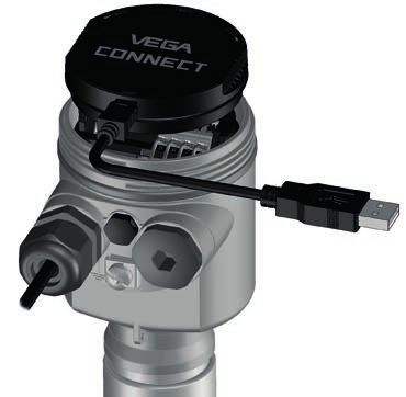
1 About this document

                            1     About this document
                            1.1    Function
                            This instruction provides all the information you need for mounting,
                            connection and setup as well as important instructions for mainte-
                            nance, fault rectification, the exchange of parts and the safety of the
                            user. Please read this information before putting the instrument into
                            operation and keep this manual accessible in the immediate vicinity
                            of the device.

                            1.2    Target group
                            This operating instructions manual is directed to trained personnel.
                            The contents of this manual must be made available to the qualified
                            personnel and implemented.

                            1.3    Symbols used
                            Document ID
                            This symbol on the front page of this instruction refers to the Docu-
                            ment ID. By entering the Document ID on www.vega.com you will
                            reach the document download.
                            Information, note, tip: This symbol indicates helpful additional infor-
                            mation and tips for successful work.
                            Note: This symbol indicates notes to prevent failures, malfunctions,
                            damage to devices or plants.
                            Caution: Non-observance of the information marked with this symbol
                            may result in personal injury.
                            Warning: Non-observance of the information marked with this symbol
                            may result in serious or fatal personal injury.
                            Danger: Non-observance of the information marked with this symbol
                            results in serious or fatal personal injury.
                            Ex applications
                            This symbol indicates special instructions for Ex applications.
                        •   List
                            The dot set in front indicates a list with no implied sequence.
                        1   Sequence of actions
                            Numbers set in front indicate successive steps in a procedure.
                            Battery disposal
                            This symbol indicates special information about the disposal of bat-
                            teries and accumulators.
                                                                                                      47247-EN-200427

4                                                          VEGAPULS 69 • Two-wire 4 … 20 mA/HART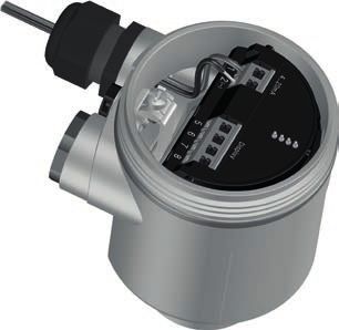
2 For your safety

                                              2     For your safety
                                              2.1    Authorised personnel
                                              All operations described in this documentation must be carried out
                                              only by trained, qualified personnel authorised by the plant operator.
                                              During work on and with the device, the required personal protective
                                              equipment must always be worn.

                                              2.2    Appropriate use
                                              VEGAPULS 69 is a sensor for continuous level measurement.
                                              You can find detailed information about the area of application in
                                              chapter "Product description".
                                              Operational reliability is ensured only if the instrument is properly
                                              used according to the specifications in the operating instructions
                                              manual as well as possible supplementary instructions.

                                              2.3    Warning about incorrect use
                                              Inappropriate or incorrect use of this product can give rise to applica-
                                              tion-specific hazards, e.g. vessel overfill through incorrect mounting
                                              or adjustment. Damage to property and persons or environmental
                                              contamination can result. Also, the protective characteristics of the
                                              instrument can be impaired.

                                              2.4    General safety instructions
                                              This is a state-of-the-art instrument complying with all prevailing
                                              regulations and directives. The instrument must only be operated in a
                                              technically flawless and reliable condition. The operator is responsi-
                                              ble for the trouble-free operation of the instrument. When measuring
                                              aggressive or corrosive media that can cause a dangerous situation
                                              if the instrument malfunctions, the operator has to implement suitable
                                              measures to make sure the instrument is functioning properly.
                                              The safety instructions in this operating instructions manual, the na-
                                              tional installation standards as well as the valid safety regulations and
                                              accident prevention rules must be observed by the user.
                                              For safety and warranty reasons, any invasive work on the device
                                              beyond that described in the operating instructions manual may be
                                              carried out only by personnel authorised by the manufacturer. Arbi-
                                              trary conversions or modifications are explicitly forbidden. For safety
                                              reasons, only the accessory specified by the manufacturer must be
                                              used.
                                              To avoid any danger, the safety approval markings and safety tips on
                                              the device must also be observed.
                                              The low transmitting power of the radar sensor is far below the inter-
47247-EN-200427

                                              nationally approved limits. No health impairments are to be expected
                                              with intended use. The band range of the transmission frequency can
                                              be found in chapter "Technical data".

                  VEGAPULS 69 • Two-wire 4 … 20 mA/HART                                                                 5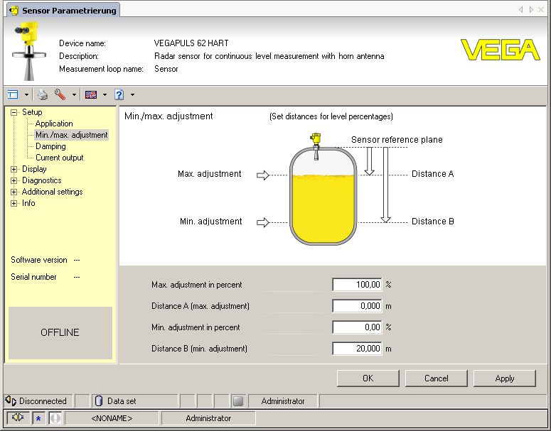
2 For your safety

                    2.5     EU conformity
                    The device fulfils the legal requirements of the applicable EU direc-
                    tives. By affixing the CE marking, we confirm the conformity of the
                    instrument with these directives.
                    The EU conformity declaration can be found on our homepage.

                    2.6     NAMUR recommendations
                    NAMUR is the automation technology user association in the process
                    industry in Germany. The published NAMUR recommendations are
                    accepted as the standard in field instrumentation.
                    The device fulfils the requirements of the following NAMUR recom-
                    mendations:
                    •   NE 43 – Signal level for fault information from measuring transduc-
                        ers
                    •   NE 53 – Compatibility of field devices and display/adjustment
                        components
                    •   NE 107 – Self-monitoring and diagnosis of field devices
                    For further information see www.namur.de.

                    2.7     Radio license for Europe
                    The instrument was tested according to the latest issue of the follow-
                    ing harmonized standards:
                    •   EN 302372 - Tank Level Probing Radar
                    •   EN 302729 - Level Probing Radar
                    It is hence approved for use inside and outside closed vessels in
                    countries of the EU.
                    Use is also approved in EFTA countries, provided the respective
                    standards have been implemented.
                    For operation inside of closed vessels, points a to f in annex E of
                    EN 302372 must be fulfilled.
                    For operation outside of closed vessels, the following conditions must
                    be fulfilled:
                    •   The instrument must be stationary mounted and the antenna
                        directed vertically downward
                    •   The instrument may only be used outside closed vessels in the
                        version with G1½ or 1½ NPT thread with integrated horn antenna.
                    •   The mounting location must be at least 4 km away from radio
                        astronomy stations, unless special permission was granted by the
                        responsible national approval authority
                    •   When installed within 4 to 40 km of a radio astronomy station,
                        the instrument must not be mounted higher than 15 m above the
                        ground.
                                                                                              47247-EN-200427

                    A list of the respective radio astronomy stations can be found in chap-
                    ter "Appendix" of the operating instructions.

6                                                  VEGAPULS 69 • Two-wire 4 … 20 mA/HART
2 For your safety
2.8 Radio license for USA
This approval is only valid for USA. Hence the following text is only
available in the English language:
This device complies with Part 15 of the FCC Rules. Operation is
subject to the following two conditions:
• This device may not cause interference, and
• This device must accept any interference, including interference
that may cause undesired operation of the device
This device is approved for unrestricted use only inside closed,
stationary vessels made of metal or concrete. From electronics index
.-03 the use in containers made of reinforced fiberglass is also permit-
ted.
For operation outside of closed vessels, the following conditions must
be fulfilled:
• This device shall be installed and maintained to ensure a verti-
cally downward orientation of the transmit antenna's main beam.
Furthermore, the use of any mechanism that does not allow the
main beam of the transmitter to be mounted vertically downward is
prohibited.
• Operation of the instrument is only permitted with thread G1½ or
1½ NPT with integrated horn antenna.
• This device shall be installed only at fixed locations. The LPR
device shall not operate while being moved or while inside a mov-
ing container.
• Hand-held applications are prohibited.
• Marketing to residential consumers is prohibited.
Changes or modifications not expressly approved by the manufac-
turer could void the user’s authority to operate this equipment.
2.9 Radio license for Canada
This approval is only valid for Canada. Hence the following texts are
only available in the English/French language:
This device complies with Industry Canada's license-exempt RSS
standard(s). Operation is subject to the following conditions:
• This device may not cause interference, and
• This device must accept any interference, including interference
that may cause undesired operation of the device
This device has been approved for both closed containers and open-
air environments with the following limitations:
• Closed Containers: For installations utilizing a tilt during installa-
tion: This device is limited to installation in a completely enclosed
container made of metal or concrete to prevent RF emissions,
47247-EN-200427
which can otherwise interfere with aeronautical navigation, the
maximum approved tilt angel is 10°. From electronics index .-03
the use in containers made of reinforced fiberglass is also permit-
ted.
VEGAPULS 69 • Two-wire 4 … 20 mA/HART 72 For your safety
• Open Air Environment: For operation outside of closed vessels,
the following condition must be fulfilled: This device shall be
installed and maintained to ensure a vertically downward orienta-
tion of the transmit antenna's main beam. Furthermore, the use of
any mechanism that does not allow the main beam of the transmit-
ter to be mounted vertically downward is prohibited.
• Operation of the instrument outside of closed vessels is only per-
mitted with G1½ or 1½ NPT with integrated horn antenna.
• The installation of the LPR/TLPR device shall be done by trained
installers, in strict compliance with the manufacturer's instructions.
• This device shall be installed only at fixed locations. The LPR
device shall not operate while being moved or while inside a mov-
ing container.
• Hand-held applications are prohibited.
• Marketing to residential consumers is prohibited.
• The use of this device is on a "no-interference, no-protection"
basis. That is, the user shall accept operations of high-powered
radar in the same frequency band which may interfere with or
damage this device.
• However, devices found to interfere with primary licensing opera-
tions will be required to be removed at the user's expense.
• The installer/user of this device shall ensure that it is at least 10 km
from the Dominion Astrophysical Radio Observatory (DRAO) near
Penticton, British Columbia. The coordinates of the DRAO are
latitude 49°19′15″ N and longitude 119°37′12″W. For devices not
meeting this 10 km separation (e.g., those in the Okanagan Valley,
British Columbia,) the installer/user must coordinate with, and
obtain the written concurrence of, the Director of the DRAO before
the equipment can be installed or operated. The Director of the
DRAO may be contacted at 250-497-2300 (tel.)or 250-497-2355
(fax). (Alternatively, the Manager, Regulatory Standards, Industry
Canada, may be contacted.)
Le présent appareil est conforme aux CNR d’Industrie Canada ap-
plicables aux appareils radio exempts de licence. L’exploitation est
autorisée aux conditions suivantes :
• L’appareil ne doit pas produire de brouillage; et
• L’utilisateur de l’appareil doit accepter tout brouillage radioélect-
rique subi, même si le brouillage est susceptible d’en compromet-
tre le fonctionnement.
Cet appareil est homologué pour une utilisation dans les cuves fer-
mées et les environnements ouverts avec les restrictions suivantes :
• Cuves fermées : Pour les installations impliquant une inclinaison
lors de l'installation : cet appareil ne doit être installé que dans
une cuve totalement fermée en métal ou en béton, pour empêcher
les émissions RF susceptibles d'interférer avec la navigation
47247-EN-200427
aéronautique. L'angle d'inclinaison maximum autorisé est de 10°.
De l'indice électronique .-03, l'utilisation dans des conteneurs
fabriqués en fibre de verre est également permise.
• Environnement ouvert : Pour l'utilisation hors des cuves fermées,
la condition suivante doit être remplie : L'appareil doit être installé
8 VEGAPULS 69 • Two-wire 4 … 20 mA/HART2 For your safety
et entretenu de manière à garantir une orientation verticale vers
le bas du faisceau principal de l’antenne émettrice. De plus,
l’utilisation de tout mécanisme ne permettant pas l’orientation ver-
ticale vers le bas du faisceau principal de l’émetteur est interdite
• Il est uniquement autorisé d'utiliser la version d'appareil avec le
filetage G1½ ou 1½ NPT en environnements ouvertes.
• L’installation d’un dispositif LPR ou TLPR doit être effectuée
par des installateurs qualifiés, en pleine conformité avec les
instructions du fabricant.
• Cet appareil ne doit être installé qu'à des emplacements fixes.
L’appareil LPR ne doit pas être utilisé pendant qu’il est en train
d’être déplacé ou se trouve dans un conteneur en mouvement.
• Les applications portables sont interdites.
• La vente à des particuliers est interdite.
• Ce dispositif ne peut être exploité qu'en régime de non-brouillage
et de non-protection, c'est-à-dire que l'utilisateur doit accepter que
des radars de haute puissance de la même bande de fréquences
puissent brouiller ce dispositif ou même l'endommager.
• D'autre part, les capteurs de niveau qui perturbent une exploita-
tion autorisée par licence de fonctionnement principal doivent être
enlevés aux frais de leur utilisateur.
• La personne qui installe/utilise ce capteur de niveau doit s'assurer
qu'il se trouve à au moins 10 km de l'Observatoire fédéral de
radioastrophysique (OFR) de Penticton en Colombie-Britannique.
Les coordonnées de l'OFR sont : latitude N 49° 19′ 15″, longitude
O 119° 37′ 12″. La personne qui installe/utilise un dispositif ne
pouvant respecter cette distance de 10 km (p. ex. dans la vallée
de l'Okanagan [Colombie-Britannique]) doit se concerter avec le
directeur de l'OFR afin d’obtenir de sa part une autorisation écrite
avant que l'équipement ne puisse être installé ou mis en marche.
Le directeur de l'OFR peut être contacté au 250-497-2300 (tél.) ou
au 250-497-2355 (fax). (Le Directeur des Normes réglementaires
d'Industrie Canada peut également être contacté).
2.10 Installation and operation in the USA and
Canada
This information is only valid for USA and Canada. Hence the follow-
ing text is only available in the English language.
Installations in the US shall comply with the relevant requirements of
the National Electrical Code (ANSI/NFPA 70).
Installations in Canada shall comply with the relevant requirements of
the Canadian Electrical Code
A Class 2 power supply unit has to be used for the installation in the
USA and Canada.
2.11 Environmental instructions
47247-EN-200427
Protection of the environment is one of our most important duties.
That is why we have introduced an environment management system
with the goal of continuously improving company environmental pro-
VEGAPULS 69 • Two-wire 4 … 20 mA/HART 92 For your safety
tection. The environment management system is certified according
to DIN EN ISO 14001.
Please help us fulfil this obligation by observing the environmental
instructions in this manual:
• Chapter "Packaging, transport and storage"
• Chapter "Disposal"
47247-EN-200427
10 VEGAPULS 69 • Two-wire 4 … 20 mA/HART3 Product description
3 Product description
3.1 Configuration
Scope of delivery The scope of delivery encompasses:
• VEGAPULS 69 radar sensor
• Hexagon socket wrench (for instruments with swivel holder)
The further scope of delivery encompasses:
• Documentation
–– Quick setup guide VEGAPULS 69
–– Instructions for optional instrument features
–– Ex-specific "Safety instructions" (with Ex versions)
–– If necessary, further certificates
Information:
Optional instrument features are also described in this operating
instructions manual. The respective scope of delivery results from the
order specification.
Scope of this operating This operating instructions manual applies to the following instrument
instructions versions:
• Hardware version from 1.0.3
• Software version from 1.3.2
Type label The type label contains the most important data for identification and
use of the instrument:
47247-EN-200427
VEGAPULS 69 • Two-wire 4 … 20 mA/HART 113 Product description
1
2
7
3 6
5
4
Fig. 1: Layout of the type label (example)
1 Instrument type
2 Product code
3 Approvals
4 Voltage supply and signal output, electronics
5 Protection rating
6 Measuring range (measurement accuracy optional)
7 Process and ambient temperature, process pressure
8 Material wetted parts
9 Hardware and software version
10 Order number
11 Serial number of the instrument
12 Data matrix code for VEGA Tools app
13 Symbol of the device protection class
14 ID numbers, instrument documentation
15 Reminder to observe the instrument documentation
16 Notified authority for CE marking
17 Approval directive
Serial number - Instru- The type label contains the serial number of the instrument. With it
ment search you can find the following instrument data on our homepage:
• Product code (HTML)
• Delivery date (HTML)
• Order-specific instrument features (HTML)
• Operating instructions and quick setup guide at the time of ship-
ment (PDF)
• Order-specific sensor data for an electronics exchange (XML)
• Test certificate (PDF) - optional
Move to "www.vega.com" and enter in the search field the serial
number of your instrument.
Alternatively, you can access the data via your smartphone:
• Download the VEGA Tools app from the "Apple App Store" or the
"Google Play Store"
• Scan the DataMatrix code on the type label of the instrument or
• Enter the serial number manually in the app
47247-EN-200427
3.2 Principle of operation
Application area The VEGAPULS 69 is a radar sensor for continuous level measure-
ment of bulk solids under different process conditions.
12 VEGAPULS 69 • Two-wire 4 … 20 mA/HART3 Product description
It is ideal for level measurement in very high silos, large bunkers and
segmented vessels. The very good signal focussing ensures a simple
setup and reliable measurement.
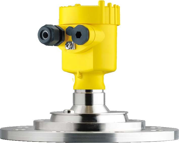
The VEGAPULS 69 is available with different antenna systems:
1 2 3
Fig. 2: Antenna systems VEGAPULS 69
1 Metal-jacketed lens antenna
2 Plastic horn antenna
3 Thread with integrated horn antenna
Functional principle The instrument emits a continuous, frequency-modulated radar signal
through its antenna. The emitted signal is reflected by the medium
and received by the antenna as an echo with modified frequency. The
frequency change is proportional to the distance and is converted into
the level.
3.3 Packaging, transport and storage
Packaging Your instrument was protected by packaging during transport. Its
capacity to handle normal loads during transport is assured by a test
based on ISO 4180.
The packaging consists of environment-friendly, recyclable card-
board. For special versions, PE foam or PE foil is also used. Dispose
of the packaging material via specialised recycling companies.
Transport Transport must be carried out in due consideration of the notes on the
transport packaging. Nonobservance of these instructions can cause
damage to the device.
Transport inspection The delivery must be checked for completeness and possible transit
damage immediately at receipt. Ascertained transit damage or con-
cealed defects must be appropriately dealt with.
Storage Up to the time of installation, the packages must be left closed and
stored according to the orientation and storage markings on the
47247-EN-200427
outside.
Unless otherwise indicated, the packages must be stored only under
the following conditions:
• Not in the open
• Dry and dust free
VEGAPULS 69 • Two-wire 4 … 20 mA/HART 133 Product description
• Not exposed to corrosive media
• Protected against solar radiation
• Avoiding mechanical shock and vibration
Storage and transport • Storage and transport temperature see chapter "Supplement -
temperature Technical data - Ambient conditions"
• Relative humidity 20 … 85 %
Lifting and carrying With instrument weights of more than 18 kg (39.68 lbs) suitable and
approved equipment must be used for lifting and carrying.
3.4 Accessories
The instructions for the listed accessories can be found in the down-
load area on our homepage.
PLICSCOM The display and adjustment module is used for measured value indi-
cation, adjustment and diagnosis.
The integrated Bluetooth module (optional) enables wireless adjust-
ment via standard adjustment devices.
VEGACONNECT The interface adapter VEGACONNECT enables the connection of
communication-capable instruments to the USB interface of a PC.
VEGADIS 81 The VEGADIS 81 is an external display and adjustment unit for VEGA
plics® sensors.
VEGADIS adapter The VEGADIS adapter is an accessory part for sensors with double
chamber housings. It enables the connection of VEGADIS 81 to the
sensor housing via an M12 x 1 plug.
VEGADIS 82 VEGADIS 82 is suitable for measured value indication and adjustment
of sensors with HART protocol. It is looped into the 4 … 20 mA/HART
signal cable.
PLICSMOBILE T81 The PLICSMOBILE T81 is an external GSM/GPRS/UMTS radio unit
for transmission of measured values and for remote parameter adjust-
ment of HART sensors.
PLICSMOBILE 81 PLICSMOBILE 81 is an internal GSM/GPRS/UMTS radio unit for
HART sensors for transmitting measured values and for remote
parameterization.
Overvoltage protection The overvoltage arrester B81-35 is used instead of the terminals in
the single or double chamber housing.
Protective cover The protective cover protects the sensor housing against soiling and
intense heat from solar radiation.
47247-EN-200427
Flanges Screwed flanges are available in different versions according to the
following standards: DIN 2501, EN 1092-1, BS 10, ASME B 16.5,
JIS B 2210-1984, GOST 12821-80.
14 VEGAPULS 69 • Two-wire 4 … 20 mA/HART4 Mounting
4 Mounting
4.1 General instructions
Protection against mois- Protect your instrument against moisture ingress through the following
ture measures:
• Use a suitable connection cable (see chapter "Connecting to
power supply")
• Tighten the cable gland or plug connector
• Lead the connection cable downward in front of the cable entry or
plug connector
This applies mainly to outdoor installations, in areas where high
humidity is expected (e.g. through cleaning processes) and on cooled
or heated vessels.
Note:
Make sure that the degree of contamination specified in chapter
"Technical data" meets the existing ambient conditions.
Note:
Make sure that during installation or maintenance no moisture or dirt
can get inside the instrument.
To maintain the housing protection, make sure that the housing lid is
closed during operation and locked, if necessary.
Process conditions Note:
For safety reasons, the instrument must only be operated within the
permissible process conditions. You can find detailed information on
the process conditions in chapter "Technical data" of the operating
instructions or on the type label.
Hence make sure before mounting that all parts of the instrument ex-
posed to the process are suitable for the existing process conditions.
These are mainly:
• Active measuring component
• Process fitting
• Process seal
Process conditions in particular are:
• Process pressure
• Process temperature
• Chemical properties of the medium
• Abrasion and mechanical influences
Radio license for USA/ The mounting position and orientation of the sensor must take into ac-
Canada count the limitations in chapter "For your safety", "Radio approval for
USA" "Radio approval for Canada" of this operating instructions.
47247-EN-200427
4.2 Mounting versions, plastic horn antenna
Mounting strap The optional mounting strap allows simple mounting of the instrument
on a wall, ceiling or boom. Especially in the case of open vessels, this
VEGAPULS 69 • Two-wire 4 … 20 mA/HART 154 Mounting
is a simple and effective way to align the sensor to the surface of the
bulk solid material.
The following versions are available:
• Length 300 mm
• Length 170 mm
Mounting strap - Ceiling The instrument is normally mounted vertically with a bracket on the
mounting ceiling.
This allows swivelling the sensor up to 180° for optimal orientation
and rotating for optimal connection.
Fig. 3: Ceiling mounting via the mounting strap with length 300 mm
Mounting strap - Wall As an alternative the strap mounting is carried out horizontally or
mounting obliquely.
> 200 mm
(7.87")
Fig. 4: Wall mounting horizontally via the mounting strap with length 170 mm
47247-EN-200427
16 VEGAPULS 69 • Two-wire 4 … 20 mA/HART4 Mounting
Fig. 5: Wall mounting with inclined wall via the mounting strap with length
300 mm
Flange Two versions are available for mounting the instrument on a socket:
• Combi compression flange
• Adapter flange
Combi compression flange
The combi compression flange is suitable for different vessel flanges
DN 80, ASME 3" and JIS 80. It comes not sealed against the radar
sensor and can thus only be used unpressurized. It can be retrofitted
on instruments with single chamber housing, retrofitting to a double
chamber housing is not possible.
1
Fig. 6: Combi compression flange
1 Combi compression flange
Adapter flange
The adapter flange is available from DN 100, ASME 4" and JIS 100. It
is permanently connected with the radar sensor and sealed.
47247-EN-200427
VEGAPULS 69 • Two-wire 4 … 20 mA/HART 174 Mounting
1
2
3
Fig. 7: Adapter flange
1 Connection screw
2 Adapter flange
3 Process seal
4.3 Mounting preparations, mounting strap
The mounting strap is supplied unassembled (optionally) and must be
screwed to the sensor before setup with three hexagon socket screws
M5 x 10 and spring washers. Max. torque, see chapter "Technical
data". Required tools: Allen wrench size 4.
There are two different variants of screwing the strap to the sensor,
see following illustration:
1 2
Fig. 8: Mounting strap for screwing to the sensor
1 For angle of inclination in steps
2 For angle of inclination, infinitely variable
Depending on the selected variant, the sensor can be rotated in the
strap:
• Single chamber housing
47247-EN-200427
–– Angle of inclination in three steps 0°, 90° and 180°
–– Angle of inclination 180°, infinitely variable
• Double chamber housing
–– Angle of inclination in two steps 0° and 90°
–– Angle of inclination 90°, infinitely variable
18 VEGAPULS 69 • Two-wire 4 … 20 mA/HART4 Mounting
Fig. 9: Adjustment of the angle of inclination
Fig. 10: Turning by fastening in the centre
4.4 Mounting instructions
Polarisation Radar sensors for level measurement emit electromagnetic waves.
The polarization is the direction of the electrical component of these
waves.
The polarization direction is marked by a nose on the housing, see
following drawing:
1
Fig. 11: Position of the polarisation
1 Nose for marking the direction of polarisation
Note:
When the housing is rotated, the direction of polarization changes
and hence the influence of the false echo on the measured value.
47247-EN-200427
Please keep this in mind when mounting or making changes later.
Installation position Mount the sensor at least 200 mm (7.874 in) away from the vessel
wall.
VEGAPULS 69 • Two-wire 4 … 20 mA/HART 194 Mounting
200 mm
(7.87")
Fig. 12: Mounting the radar sensor on the vessel top
If you cannot maintain this distance, you should carry out a false
signal suppression during setup. This applies particularly if buildup on
the vessel wall is expected. In such cases, we recommend repeating
the false signal suppression at a later date with existing buildup.
Inflowing medium The instrument should not be mounted too close to the inflowing
medium, as the radar signal could be disrupted.
Silo with filling from top
The optimal mounting position is opposite the filling aperture. To avoid
heavy soiling, the distance to any filter or dust exhauster should be as
large as possible.
Fig. 13: Mounting of the radar sensor with inflowing medium
Silo with lateral filling
In bulk solids silos with lateral pneumatic filling the instrument should
47247-EN-200427
not be mounted above the filling stream, as the radar signal will be
disrupted. The optimal mounting position is to the side of the filling
aperture. To avoid heavy soiling, the distance to any filter or dust
exhauster should be as large as possible.
20 VEGAPULS 69 • Two-wire 4 … 20 mA/HART4 Mounting
Fig. 14: Mounting of the radar sensor with inflowing medium
Mounting socket For socket mounting, the socket should be as short as possible and
its end rounded. This reduces false reflections from the socket.
With threaded connection, the antenna end should protrude at least
5 mm (0.2 in) out of the socket.
ca. 5 mm
1 2 3
Fig. 15: Recommended socket mounting with different versions of VEGAPULS
69
47247-EN-200427
1 Metal-jacketed lens antenna
2 Plastic horn antenna
3 Thread with integrated horn antenna
VEGAPULS 69 • Two-wire 4 … 20 mA/HART 214 Mounting
If the reflective properties of the medium are good, you can mount
VEGAPULS 69 on sockets longer than the antenna. The socket end
should be smooth and burr-free, if possible also rounded.
Note:
When mounting on longer sockets, we recommend carrying out a
false signal suppression (see chapter "Parameter adjustment").
You will find recommended values for socket heights in the following
illustration or the tables. The values come from typical applications.
Deviating from the proposed dimensions, also longer sockets are
possible, however the local conditions must be taken into account.
h
h
h
d d d
1 2 3
Fig. 16: Socket mounting with deviating socket dimensions with different ver-
sions of VEGAPULS 69
1 Metal-jacketed lens antenna
2 Plastic horn antenna
3 Thread with integrated horn antenna
Metal-jacketed lens antenna
Socket diameter d Socket length h
100 mm 4" ≤ 500 mm ≤ 19.7 in
150 mm 6" ≤ 800 mm ≤ 31.5 in
Plastic horn antenna
Socket diameter d Socket length h
80 mm 3" ≤ 400 mm ≤ 15.8 in
100 mm 4" ≤ 500 mm ≤ 19.7 in
150 mm 6" ≤ 800 mm ≤ 31.5 in
Thread with integrated horn antenna
47247-EN-200427
Socket diameter d Socket length h
40 mm 1½" ≤ 150 mm ≤ 5.9 in
50 mm 2" ≤ 200 mm ≤ 7.9 in
22 VEGAPULS 69 • Two-wire 4 … 20 mA/HART4 Mounting
Socket diameter d Socket length h
80 mm 3" ≤ 300 mm ≤ 11.8 in
100 mm 4" ≤ 400 mm ≤ 15.8 in
150 mm 6" ≤ 600 mm ≤ 23.6 in
Orientation In a cylindrical silo with conical outlet, the mounting is carried out on
a third up to the half of the vessel radius from outside (see following
drawing).
r
1/3 r...1/2 r
Fig. 17: Mounting position and orientation
Direct the sensor in such a way that the radar signal reaches the
lowest vessel level. Hence it is possible to detect the complete vessel
volume.
Tip:
The easiest way to align the sensor is with the optional swivelling
holder. Determine the suitable inclination angle and check the align-
ment with the alignment aid in the VEGA Tools app on the sensor.
Alternatively, the angle of inclination can be determined using the
47247-EN-200427
following drawing and table. It depends on the measuring distance "d"
and the distance "a" between vessel centre and mounting position.
Check the alignment with a suitable level or water level.
VEGAPULS 69 • Two-wire 4 … 20 mA/HART 234 Mounting
α
d
a
Fig. 18: Determination of the angle of inclination for alignment of VEGAPULS 69
Distance d 2° 4° 6° 8° 10°
(m)
2 0.1 0.1 0.2 0.3 0.4
4 0.1 0.3 0.4 0.6 0.7
6 0.2 0.4 0.6 0.8 1.1
8 0.3 0.6 0.8 1.1 1.4
10 0.3 0.7 1.1 1.4 1.8
15 0.5 1 1.6 2.1 2.6
20 0.7 1.4 2.1 2.8 3.5
25 0.9 1.7 2.6 3.5 4.4
30 1 2.1 3.2 4.2 5.3
35 1.2 2.4 3.7 4.9 6.2
40 1.4 2.8 4.2 5.6 7.1
45 1.6 3.1 4.7 6.3 7.9
50 1.7 3.5 5.3 7 8.8
60 2.1 4.2 6.3 8.4 10.5
47247-EN-200427
70 2.4 4.9 7.3 9.7 12.2
80 2.8 5.6 8.4 11.1 13.9
90 3.1 6.3 9.4 12.5 15.6
24 VEGAPULS 69 • Two-wire 4 … 20 mA/HART4 Mounting
Distance d 2° 4° 6° 8° 10°
(m)
100 3.5 7 10.5 13.9 17.4
110 3.8 7.7 11.5 15.3 19.1
120 4.2 8.4 12.5 16.7 20.8
Example:
In a vessel 20 m high, the installation position of the sensor is 1.4 m
from the vessel centre.
The necessary angle of inclination of 4° can be read out from this
table.
Proceed as follows to adjust the angle of inclination with the swivelling
holder:
1. Loosen the terminal screws of the swivel holder by one turn. Use
a hexagon socket wrench, size 5.
1
Fig. 19: VEGAPULS 69 with swivelling holder
1 Terminal screws (6 pcs.)
2. Align the sensor, check angle of inclination
Note:
The max. angle of inclination of the swivelling holder is approx. 10°
3. Re-tighten the terminal screws, max. torque see chapter "Techni-
cal data".
Vessel installations The mounting location of the radar sensor should be a place where no
other equipment or fixtures cross the path of the radar signals.
Vessel installations, such as e.g. ladders, limit switches, heating spi-
rals, struts, etc., can cause false echoes and impair the useful echo.
Make sure when planning your measuring point that the radar sensor
has a "clear view" to the measured product.
In case of existing vessel installations, a false signal suppression
should be carried out during setup.
If large vessel installations such as struts or supports cause false
47247-EN-200427
echoes, these can be attenuated through supplementary measures.
Small, inclined sheet metal baffles above the installations scatter the
radar signals and prevent direct interfering reflections.
VEGAPULS 69 • Two-wire 4 … 20 mA/HART 254 Mounting
Fig. 20: Cover flat, large-area profiles with deflectors
Material heaps Large material heaps are best measured with several instruments,
which can be mounted on e.g. traverse cranes. For this type of ap-
plication it is advantageous to orient the sensor perpendicular to the
bulk solid surface.
The sensors do not influence each other.
Information:
Keep in mind that for these applications, the sensors are designed
for relatively slow level changes. If the sensor is used on a movable
boom, the max. measuring rate must be observed (see chapter
"Technical data").
Fig. 21: Radar sensors on traverse crane
Mounting in the vessel Instruments for a temperature range up to 200° C have a spacer
insulation between process fitting and electronics housing. This spacer is used
to thermally decouple the electronics from the high process tempera-
tures.
Information:
The spacer may only be incorporated up to a maximum of 50 mm into
the vessel insulation. Only then is a reliable temperature decoupling
guaranteed.
47247-EN-200427
26 VEGAPULS 69 • Two-wire 4 … 20 mA/HART4 Mounting
1
2
max. 50 mm
(1.97")
3
Fig. 22: Mounting the instrument on insulated vessels.
1 Electronics housing
2 Spacer
3 Vessel insulation
Mounting in multiple The walls of multiple-chamber silos are often made of profile material,
chamber silo e.g. profile sheeting, to ensure the required stability. If the radar sen-
sor is mounted very close to a heavily structured vessel wall, substan-
tial interfering reflections can be generated. Thus the sensor should
be mounted at the largest possible distance from the separating wall.
The best mounting location is on the outer wall of the silo, with the
sensor pointing towards the discharge opening in the silo centre. This
can be accomplished, for example, with the mounting strap.
Fig. 23: Installation and orientation in multiple chamber silos
47247-EN-200427
VEGAPULS 69 • Two-wire 4 … 20 mA/HART 274 Mounting
Fig. 24: Installation and orientation in multiple chamber silos
Dust deposits - Rinsing To avoid heavy buildup and dust on the antenna, the sensor should
air connection not be mounted close to the dust exhauster inside the vessel.
To protect the sensor against buildup, particularly in case of strong
condensation, air rinsing is recommended.
Metal-jacketed lens antenna
The VEGAPULS 69 with metal-jacketed lens antenna is equipped
with a rinsing air connection as a standard feature, see following
graphics.
1
Fig. 25: Rinsing air connection on metal-jacketed lens antenna
Plastic horn antenna
47247-EN-200427
The VEGAPULS 69 with plastic horn antenna is optionally available
with a rinsing air connection. The mechanical configuration differs
according to the flange version, see following graphics.
28 VEGAPULS 69 • Two-wire 4 … 20 mA/HART4 Mounting
Fig. 26: Rinsing air connection with compression flange
Fig. 27: Rinsing air connection with adapter flange
You can find details on the rinsing air connection in chapter "Technical
data".
47247-EN-200427
VEGAPULS 69 • Two-wire 4 … 20 mA/HART 295 Connecting to power supply
5 Connecting to power supply
5.1 Preparing the connection
Safety instructions Always keep in mind the following safety instructions:
• Carry out electrical connection by trained, qualified personnel
authorised by the plant operator
• If overvoltage surges are expected, overvoltage arresters should
be installed
Warning:
Only connect or disconnect in de-energized state.
Voltage supply Power supply and current signal are carried on the same two-wire
cable. The operating voltage can differ depending on the instrument
version.
The data for power supply are specified in chapter "Technical data".
Provide a reliable separation between the supply circuit and the
mains circuits according to DIN EN 61140 VDE 0140-1.
Power the instrument via an energy-limited circuit acc. to IEC 61010-
1, e.g. via Class 2 power supply unit.
Keep in mind the following additional factors that influence the operat-
ing voltage:
• Lower output voltage of the power supply unit under nominal load
(e.g. with a sensor current of 20.5 mA or 22 mA in case of fault)
• Influence of additional instruments in the circuit (see load values in
chapter "Technical data")
Connection cable The instrument is connected with standard two-wire cable without
shielding. If electromagnetic interference is expected which is above
the test values of EN 61326-1 for industrial areas, shielded cable
should be used.
Use cable with round cross section for instruments with housing and
cable gland. Use a cable gland suitable for the cable diameter to
ensure the seal effect of the cable gland (IP protection rating).
Shielded cable generally necessary in HART multidrop mode.
Cable glands Metric threads
In the case of instrument housings with metric thread, the cable
glands are screwed in at the factory. They are sealed with plastic
plugs as transport protection.
Note:
You have to remove these plugs before electrical connection.
NPT thread
47247-EN-200427
In the case of instrument housings with self-sealing NPT threads, it is
not possible to have the cable entries screwed in at the factory. The
free openings for the cable glands are therefore covered with red dust
protection caps as transport protection.
30 VEGAPULS 69 • Two-wire 4 … 20 mA/HART5 Connecting to power supply
Note:
Prior to setup you have to replace these protective caps with ap-
proved cable glands or close the openings with suitable blind plugs.
On plastic housings, the NPT cable gland or the Conduit steel tube
must be screwed into the threaded insert without grease.
Max. torque for all housings, see chapter "Technical data".
Cable screening and If shielded cable is required, the cable screening must be connected
grounding on both ends to ground potential. In the sensor, the cable screening
is connected directly to the internal ground terminal. The ground ter-
minal on the outside of the housing must be connected to the ground
potential (low impedance).
In Ex systems, the grounding is carried out according to the installa-
tion regulations.
In electroplating plants as well as plants for cathodic corrosion protec-
tion it must be taken into account that significant potential differences
exist. This can lead to unacceptably high currents in the cable screen
if it is grounded at both ends.
Information:
The metallic parts of the instrument (process fitting, sensor, concen-
tric tube, etc.) are connected with the internal and external ground
terminal on the housing. This connection exists either directly via
the conductive metallic parts or, in case of instruments with external
electronics, via the screen of the special connection cable.
You can find specifications on the potential connections inside the
instrument in chapter "Technical data".
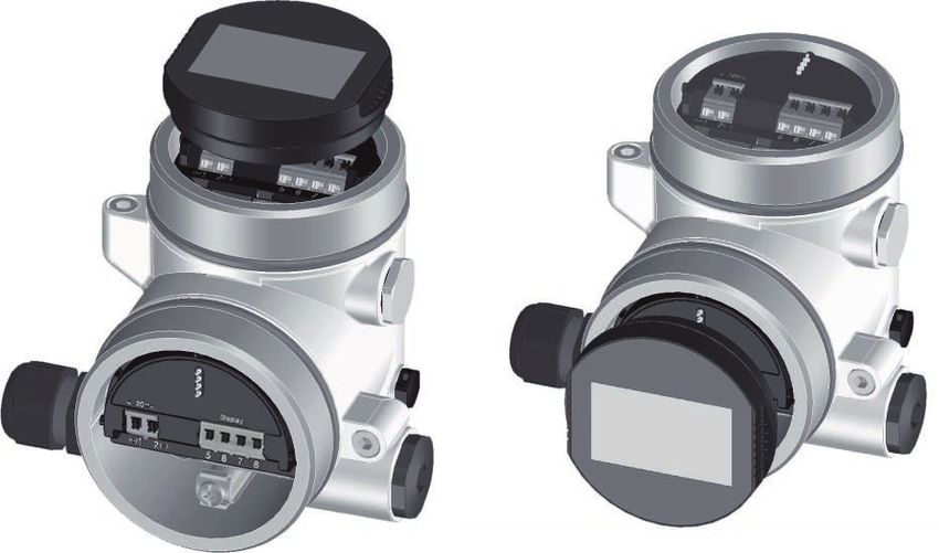
5.2 Connecting
Connection technology The voltage supply and signal output are connected via the spring-
loaded terminals in the housing.
Connection to the display and adjustment module or to the interface
adapter is carried out via contact pins in the housing.
Information:
The terminal block is pluggable and can be removed from the
electronics. To do this, lift the terminal block with a small screwdriver
and pull it out. When reinserting the terminal block, you should hear it
snap in.
Connection procedure Proceed as follows:
1. Unscrew the housing lid
2. If a display and adjustment module is installed, remove it by turn-
ing it slightly to the left
47247-EN-200427
3. Loosen compression nut of the cable gland and remove blind
plug
4. Remove approx. 10 cm (4 in) of the cable mantle, strip approx.
1 cm (0.4 in) of insulation from the ends of the individual wires
5. Insert the cable into the sensor through the cable entry
VEGAPULS 69 • Two-wire 4 … 20 mA/HART 315 Connecting to power supply
1 2
Fig. 28: Connection steps 5 and 6
1 Single chamber housing
2 Double chamber housing
6. Insert the wire ends into the terminals according to the wiring plan
Note:
Solid cores as well as flexible cores with wire end sleeves are insert-
ed directly into the terminal openings. In case of flexible cores without
end sleeves, press the terminal from above with a small screwdriver,
the terminal opening is then free. When the screwdriver is released,
the terminal closes again.
7. Check the hold of the wires in the terminals by lightly pulling on
them
8. Connect the shielding to the internal ground terminal, connect the
external ground terminal to potential equalisation
9. Tighten the compression nut of the cable entry gland. The seal
ring must completely encircle the cable
10. Reinsert the display and adjustment module, if one was installed
11. Screw the housing lid back on
The electrical connection is finished.
5.3 Wiring plan, single chamber housing
The following illustration applies to the non-Ex as well as to the Ex-ia
version.
47247-EN-200427
32 VEGAPULS 69 • Two-wire 4 … 20 mA/HART5 Connecting to power supply
Electronics and connec- 2
tion compartment
4...20mA
3
(+)1 2(-) 5 6 7 8
4
1
Fig. 29: Electronics and connection compartment - single chamber housing
1 Voltage supply, signal output
2 For display and adjustment module or interface adapter
3 For external display and adjustment unit
4 Ground terminal for connection of the cable screening
5.4 Wiring plan, double chamber housing
The following illustrations apply to the non-Ex as well as to the Ex-ia
version.
Electronics compartment
2
4...20mA
(+)1 2(-) 5 6 7 8
1 1
Fig. 30: Electronics compartment - double chamber housing
1 Internal connection to the connection compartment
2 For display and adjustment module or interface adapter
47247-EN-200427
VEGAPULS 69 • Two-wire 4 … 20 mA/HART 335 Connecting to power supply
Connection compartment
2
4...20mA Display
3
(+)1 2(-) 5 6 7 8
4
1
Fig. 31: Connection compartment - double chamber housing
1 Voltage supply, signal output
2 For display and adjustment module or interface adapter
3 For external display and adjustment unit
4 Ground terminal for connection of the cable screening
Supplementary electron- To make a second measured value available for use, you can use the
ics - Additional current supplementary electronics "Additional current output".
output
Both current outputs are passive and need a power supply.
I II
4...20mA 4...20mA
(+)1 2(-) ( +)7 8(-)
3
1 2
Fig. 32: Terminal compartment, double chamber housing, supplementary elec-
tronics "Additional current output"
1 First current output (I) - Voltage supply and signal output, sensor (HART)
2 Additional current output (II) - Voltage supply and signal output (without
HART)
3 Ground terminal for connection of the cable screening
47247-EN-200427
34 VEGAPULS 69 • Two-wire 4 … 20 mA/HART5 Connecting to power supply
Connection compart-
ment - Radio module
PLICSMOBILE 81 SIM
Status
Off On
Send
+1 2- 3
1
Fig. 33: Connection compartment - Radio module PLICSMOBILE 81
1 Voltage supply
You can find detailed information for connection in the operating
instructions "PLICSMOBILE".
5.5 Ex-d double chamber housing
Electronics compartment
2
4...20mA
(+)1 2(-) 5 6 7 8
1 1
Fig. 34: Electronics compartment - Ex-d double chamber housing
1 Internal connection to the connection compartment
2 For display and adjustment module or interface adapter
47247-EN-200427
VEGAPULS 69 • Two-wire 4 … 20 mA/HART 35You can also read